★ TRUSTED BY 321,897+ PROFESSIONALS WORLDWIDE
🏒
Trusted Business
Verified & Licensed
πŸ›‘οΈ
Virus Free Files
100% Safe Downloads
πŸ”’
Secure Payment
SSL Protected
⚑
Instant Delivery
Available Immediately
Sale!

Normet Alpha 30DC7 Concrete Sprayer Operator Manual – EQ177 Full PDF

Original price was: $44.95.Current price is: $26.95.

Complete 643-page operator and maintenance manual for the Normet Alpha 30DC7 diesel hydraulic mobile concrete sprayer (serial EQ177). Covers the SB307 spraying boom, NSP30CL concrete pump, PTR-80 compressor, wired and wireless remote controls, Nordoser XEP control system, central lubrication, safety instructions, and full electrical/hydraulic schematics.

⚑
Instant PDF Download
Available immediately
πŸ’Ύ
Save to Your Device
Download & keep forever
πŸ›‘οΈ
Antivirus Scanned
100% virus-free
🌍
Trusted Worldwide
175,000+ customers

Description

File Details

  • Manual Type: Operator & Maintenance Manual
  • Brand: Normet
  • Model: Alpha 30DC7 (Alpha 30)
  • Machine Serial Number: EQ177
  • Document Numbers: 100142661, 100120831.1, 100027009, 100063972, 100062112, 100113701, 100049453, 100049424
  • Language: English
  • Page Count: 643
  • File Format: PDF
  • Date: 2019

Chapters Covered

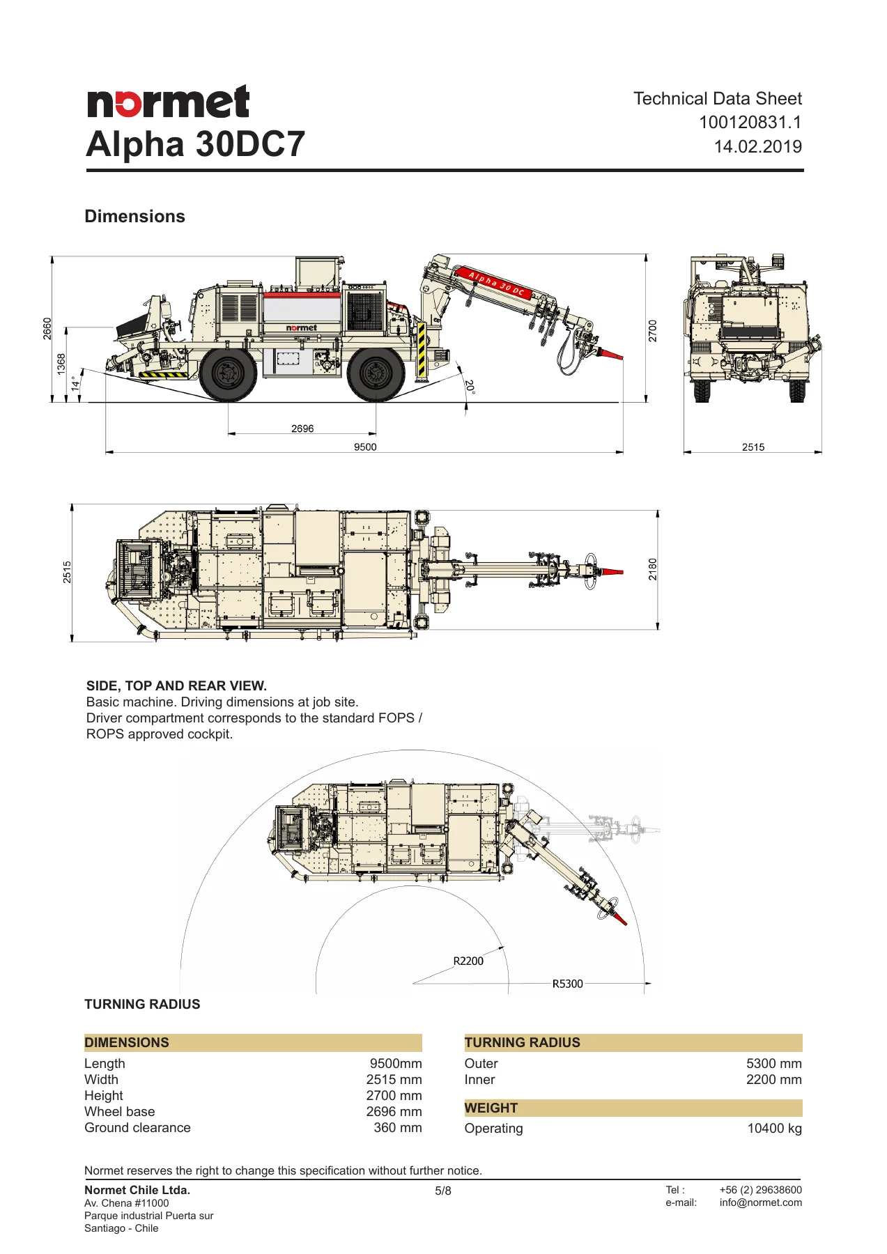
  • Technical Data Sheet β€” full machine specifications, dimensioned drawings, turning radius, weight, and performance data
  • Operations Manual β€” equipment operation and maintenance from first 100 hours through 6,000-hour intervals, including engine, axles, brakes, steering, hydraulic system, electrical system, and tyres
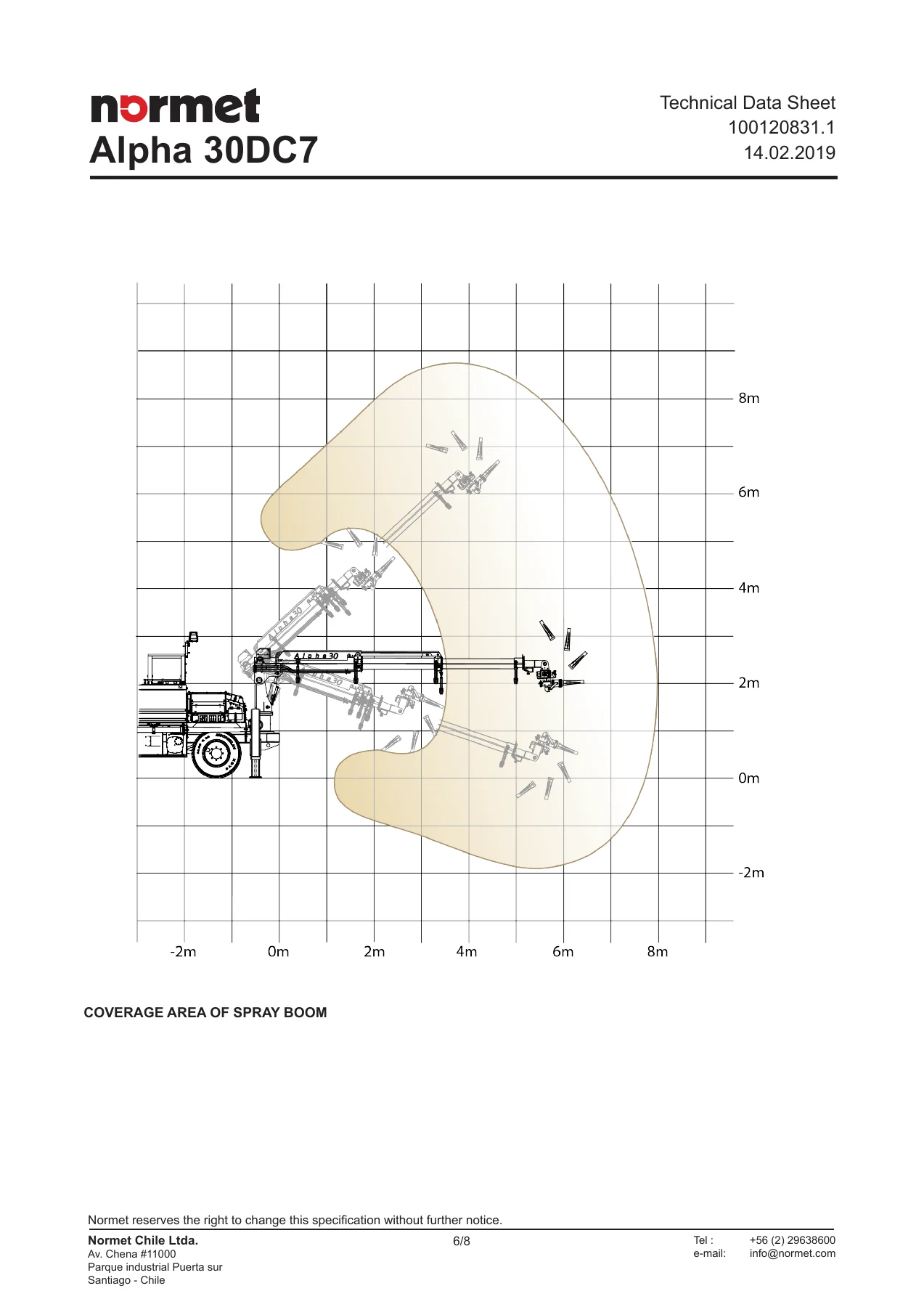
  • Spraying Boom SB307 β€” technical information, hydraulic controls, coverage area diagrams for 5 m to 8 m tunnels, boom maintenance, roller inspection, beam cleaning plates, and greasing points
  • Concrete Pump NSP30CL β€” technical data, daily through 1,000-hour maintenance procedures, delivery piston change, wear plate inspection, cutting ring service, gate valve cleaning, and troubleshooting
  • Remote Control Unit β€” wired and wireless remote control operation, joystick functions, and control system enablement
  • Safety Instructions β€” general safety, operator suitability, carrier operation, concrete spraying, ANFO and emulsion charging, electric system, hydraulic system, compressed air and water, maintenance and service, welding, and environmental instructions
  • Nordoser XEP β€” user interface operation, process settings, accelerator pump calibration, flow sensor calibration, diagnostics, data logging, and access rights
  • Compressor PTR-80 β€” operation, lubrication, maintenance, troubleshooting, and spare parts for the screw compressor
  • Central Lubrication β€” automatic greasing system operation, purging, maintenance, cycle setting, and troubleshooting
  • Schemas β€” electrical and hydraulic diagrams

This manual is the complete documentation set for the Normet Alpha 30DC7 mobile concrete sprayer, serial number EQ177. It brings together the technical data sheet, full operations manual, and the individual component manuals for the SB307 spraying boom, NSP30CL concrete pump, PTR-80 screw compressor, wired and wireless remote control units, Nordoser XEP control system, and automatic central lubrication system, plus a comprehensive safety instruction section and electrical/hydraulic schematics. The document is structured to support both daily operation and long-term maintenance planning, with clearly defined intervals from first 100-hour checks through 6,000-hour overhauls.

What This Manual Covers

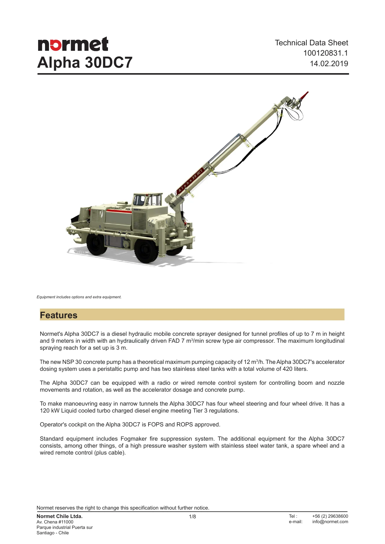
The Normet Alpha 30DC7 Concrete Sprayer Operator Manual β€” EQ177 is a complete 643-page reference for operating, maintaining, and troubleshooting this diesel hydraulic mobile concrete sprayer. The Alpha 30DC7 is designed for tunnel profiles up to 7 meters in height and 9 meters in width, and this manual documents every major system on the machine.

The operations section walks through the complete daily inspection routine: fuel level, hydraulic oil level, engine oil check, brake and steering checks, tyre pressure and condition, fire extinguisher and fire suppression system status, and the full dashboard indicator light reference. It then covers machine start-up, driving procedures, steering mode selection (crab steering, front-shaft steering, and front-and-rear steering), stabilizer operation, and shutdown. Maintenance schedules are broken down by interval β€” daily, weekly, every 200 hours, 250 hours, 500 hours, 800 hours, 1,000 hours, 1,500 hours, 3,000 hours, and 6,000 hours β€” with detailed procedures for each task.

Complete PDF Bookmark Tree

Complete Bookmarks

The complete bookmarks in the β€œNormet Alpha 30DC7 Concrete Sprayer Operator Manual – EQ177 Full PDF” are as follows:

0. Contentsp. 1
1. TDS_Alpha_30_DC7_(EN)_Rev.01p. 2
2. Alpha30_DC7_EN EQ177p. 10
Chapter 2 – EQUIPMENT OPERATION AND MAINTENANCEp. 14
1 Before operating for the first timep. 16
PROCEDURE 1 : Lubricating points for the powertrainp. 18
PROCEDURE 1 : Check the engine oil levelp. 22
PROCEDURE 2 : Check oil level in axlesp. 24
PROCEDURE 3 : Check the fuel levelp. 28
PROCEDURE 4 : Check hydraulic fluid levelp. 29
PROCEDURE 5 : Steering checkp. 30
PROCEDURE 6 : Check of the emergency/parking and service brakesp. 31
PROCEDURE 7 : Check the Hydraulic Systemp. 35
PROCEDURE 8 : Check the hydraulic pressures of the brake and steering systemp. 37
PROCEDURE 9 : Check the wheelsΒ΄ nutsΒ΄ tightening torquep. 42
PROCEDURE 10 : Check the tension of the engine beltsp. 43
PROCEDURE 11 : Visual check of the engine beltsΒ΄ conditionp. 45
PROCEDURE 12 :p. 47
PROCEDURE 13 : Check the tyresΒ΄ pressure and conditionp. 48
PROCEDURE 14 : Check the extinguisherΒ΄s conditionp. 50
PROCEDURE 15 : Enabling the fire suppression systemp. 51
PROCEDURE 16 : Safety warnings and symbolsp. 52
1 quick start guidep. 58
2 Operationp. 63
2.1 Cabin controlsp. 63
2.1.1 Dashboardp. 64
2.1.2 Dashboard indicator lightsp. 79
2.1.3 Cabin Control Panel Instrumentsp. 84
2.1.4 Identification and solution of engine failurep. 89
2.1.5 Diagnostic interfacep. 93
2.1.6 Steering wheelp. 94
2.1.7 CabinΒ΄s side panelp. 95
2.1.8 Accelerator / brake Pedalp. 98
2.2 Equipment mechanic hydraulic controlsp. 101
2.3 Additive tank controls:p. 106
3 In an emergencyp. 108
3.1 Towing Equipmentp. 108
3.2 Unblocking the equipmentΒ΄s negative hydraulic brakes systemp. 109
3.3 Enable the brake systemp. 113
4 Equipment maintenancEp. 114
4.1 First 100 hoursp. 116
PROCEDURE 1 : Change Oil in epicyclical axlep. 118
PROCEDURE 2 : Change Oil in differential axlep. 121
PROCEDURE 3 : Adjustment of negative brakep. 127
4.2 DAILYp. 128
PROCEDURE 1 : Check the fuel levelp. 130
PROCEDURE 2 : Check hydraulic fluid levelp. 131
PROCEDURE 3 : Check that there are no leaks in the enginep. 136
PROCEDURE 4 : Check the engine oil levelp. 137
PROCEDURE 5 : Check the tyresΒ΄ pressure and conditionp. 139
PROCEDURE 6 : Check the fire suppression systemp. 141
PROCEDURE 7 : Check the Hydraulic Systemp. 142
PROCEDURE 8 : Check the extinguisherΒ΄s conditionp. 144
4.3 WEEKLYp. 146
PROCEDURE 1 : Checking the powertrainp. 148
PROCEDURE 2 : Check the steering limitsp. 150
PROCEDURE 3 : Greasing points for the powertrainp. 151
4.4 MONTHLYp. 156
PROCEDURE 1 : Check oil level in differential axlep. 158
4.5 EVERY 200 HOURSp. 164
PROCEDURE 1 : Check oil level in epicyclical axlep. 166
PROCEDURE 2 : Check the wheelsΒ΄ nutsΒ΄ tightening torquep. 168
4.6 EVERY 250 HOURSp. 170
PROCEDURE 1 : Check the engineΒ΄s working parametersp. 171
4.7 EVERY 500 HOURSp. 172
PROCEDURE 1 : Replace the engine oil filterp. 174
PROCEDURE 2 : Check the wheelsΒ΄ nutsΒ΄ tightening torquep. 176
PROCEDURE 3 : Change the engine oilp. 177
PROCEDURE 4 : Check the tension of the engine beltsp. 180
PROCEDURE 5 : Clean the catalytic converterp. 182
PROCEDURE 6 : Replacing the filter on the hydraulic circuit returnp. 184
4.8 EVERY 800 WORKING HOURSp. 190
PROCEDURE 1 : Change Oil in differential axlep. 192
4.9 EVERY 1000 HOURSp. 198
PROCEDURE 1 : Replace the fuel filtersp. 200
PROCEDURE 2 : Replace the fuel prefilterp. 203
PROCEDURE 3 : Clean the radiatorp. 206
PROCEDURE 4 : Check the engine start-up systemp. 209
PROCEDURE 5 : Check the limit of wear on the v-beltp. 210
PROCEDURE 6 : Check the engine suspensionp. 211
PROCEDURE 7 : Check the hose fasteners and connectionsp. 212
PROCEDURE 8 : Check the hydraulic pressures of the brake and steering systemp. 213
PROCEDURE 9 : Replacing the hydraulic oil and suction filter on the hydrostatic pumpp. 218
PROCEDURE 10 : Change Oil in epicyclical axlep. 223
4.10 EVERY 1500 HOURSp. 226
PROCEDURE 1 : Adjust the valveΒ΄s gapp. 228
4.11 EVERY 3000 HOURSp. 232
PROCEDURE 1 : Replace splined trapezoidal beltsp. 234
4.12 EVERY 6000 HOURSp. 236
PROCEDURE 1 : Replace the injection valvesp. 238
PROCEDURE 2 : Perform a basic check-up of the enginep. 239
4.13 WHEN NEEDEDp. 240
PROCEDURE 1 : Check the fuel pre-filterp. 242
PROCEDURE 2 : Check for occasional leaks in the fire suppression systemp. 245
PROCEDURE 3 : Purge the air from the emergency/parking brakesp. 246
PROCEDURE 4 : Purge the air from the service brakesp. 248
PROCEDURE 5 : Changing tyresp. 252
PROCEDURE 6 : Replacing the air filterp. 256
PROCEDURE 7 : Replace the additive pump hosep. 258
Chapter 3 – AIR CONDITIONINGp. 264
1 OPERATIONp. 265
1.1 Controls of the air conditioning systemp. 265
1.2 Overviewsp. 266
1.3 Hot air temperature regulatorp. 267
1.4 Cold air temperature regulatorp. 268
1.5 Air intensity regulatorp. 269
3. Spraying Boomp. 270
1.3 Coverage areap. 273
1.4 The equipmentΒ΄s boomΒ΄s hydraulic controlsp. 276
2 Maintaining the boomp. 284
2.2 Maintenance proceduresp. 285
PROCEDURE 2 : Lubrication of the telescopic extensionp. 287
PROCEDURE 3 : Visual check of the hydraulic hoses and couplingsp. 289
PROCEDURE 4 : Boom greasingp. 291
PROCEDURE 5 : Revision of the boomΒ΄s structurep. 294
2.2.2 EVERY 250 HOURSp. 295
PROCEDURE 2 : Check the cleaning plates conditionp. 303
2.2.3 EVERY 500 HOURSp. 306
PROCEDURE 2 : Revision of the boomΒ΄s beamΒ΄s conditionp. 307
2.2.4 EVERY 1,000 HOURSp. 308
4. Concrete Pump NSP30CLp. 310
Concrete pump NSP30CLp. 310
Contentsp. 312
1. Introductionp. 314
1.1. Technical datap. 314
2. Safety precautionsp. 316
2.1. Servicep. 316
2.2. Hydraulicsp. 317
3. Maintenancep. 318
3.1. Lubricant recommendationsp. 318
3.2. Schedulep. 319
3.3. Maintenance proceduresp. 320
3.3.1. Daily or once per shift (10 hours)p. 320
Lubricate the pump fittings.p. 320
Check the hydraulic system for wear and leaks.p. 321
Check the tension of the stud bolts.p. 322
Check the tightness of the cutting ring.p. 323
Check the water level in the water box.p. 325
Wash the spraying pump.p. 327
3.3.2. Weekly (50 hours)p. 329
Check the condition of the grill sensor.p. 329
Check the condition of the cutting ring.p. 330
3.3.3. Every 125 hoursp. 334
Check the condition of the delivery pistons.p. 334
Check the condition of the wear plate.p. 335
Check the condition of the agitator shaft.p. 340
Check the condition of the grill supports.p. 341
Check the condition of the seals.p. 342
Check the condition of the swivel cylinder pins and bearings.p. 343
Clean the gate valve.p. 344
3.3.4. Every 250 hoursp. 345
Check the tightening torque of the bearing housing bolts.p. 345
3.3.5. Every 500 hoursp. 346
Check the condition of the delivery cylinders.p. 346
Check the condition of the outlet tube.p. 348
Check the condition of the swivel lever.p. 350
Check the condition of the bronze bushing.p. 351
3.3.6. Every 1000 hoursp. 352
Accumulator gas pressure test.p. 352
4. Repairsp. 353
4.1. Switching overlapp. 353
4.2. Delivery piston changep. 356
5. Wired remote control (100063972)p. 371
1.2 Enable the wire receptorp. 374
1.3 Turn on wireless remote controlp. 375
2 Operationp. 376
2.2 Functions of the right joystick on the wireless remote controlp. 379
2.3 Other functions of the wireless remote controlp. 383
6. Safety Instructionsp. 387
Normet Carriers and Equipmentsp. 387
Contentsp. 389
1. Forewordp. 393
2. Safety Instructions in Manualsp. 394
2.1. Operator manualp. 394
3. Instructions and Warningsp. 395
4. General Safety Instructionsp. 396
5. Instructions for the Owner and Operatorp. 397
5.1. Working environmentp. 397
5.2. Personnelp. 398
5.3. Distribution of liabilityp. 398
5.4. Trainingp. 399
6. Operator Suitability and Responsibilityp. 400
6.1. Suitabilityp. 400
6.2. Responsibilityp. 400
7. Maintaining Safetyp. 402
8. Carrierp. 404
8.1. Prior to operationp. 404
8.2. Starting upp. 405
8.3. Drivingp. 406
8.4. Operationp. 406
8.5. Ending of shiftp. 408
8.6. Stoppingp. 409
8.7. Towagep. 410
8.8. Diesel enginep. 410
8.9. Transportp. 411
8.10. Service of batteriesp. 412
9. Mobile Elevating Work Platformp. 413
9.1. Safety Instructions For Lifting Platform Operationp. 414
10. Lifting Cargop. 415
10.1. Taking The Lifter Into Usep. 415
10.2. Instructions For Safe Liftingp. 415
10.3. Liftingp. 416
11. Concrete Sprayingp. 418
11.1. Generalp. 418
11.2. Pump and boomp. 419
11.3. Operatingp. 420
11.4. Cleaningp. 422
12. Anfo Chargingp. 423
12.1. Generalp. 423
12.2. Instructionsp. 424
12.3. Explosivesp. 425
12.4. Workp. 426
12.5. Hot workp. 428
12.6. Fire preventionp. 429
13. Emulsion Chargingp. 430
13.1. General instructionsp. 430
14. Electric Systemp. 431
14.1. Electric circuitp. 431
14.2. Electric linesp. 432
14.3. Contact with an electric linep. 433
14.4. In case of bodily injuryp. 433
14.5. Service of electric equipmentp. 434
15. Hydraulic Systemp. 435
16. Compressed Air and Water Systemsp. 438
17. Maintenance and Servicep. 439
17.1. Generalp. 439
17.2. Carrierp. 441
17.3. Enginep. 442
17.4. Oils and greasesp. 442
17.5. Adding fuelp. 443
17.6. Safety Instructions for Servicing the Boomsp. 443
17.7. Safety Instructions For Servicing The Lifting Platformp. 444
17.8. Weldingp. 445
18. Environmental Instructionsp. 446
18.1. Introductionp. 446
18.2. Fuelsp. 446
18.3. Oils and oily wastep. 446
18.4. Coolantsp. 447
18.5. Cleaning solutionsp. 447
18.6. Rubberp. 447
18.7. Batteriesp. 447
18.8. Metalsp. 447
18.9. Worn componentsp. 447
18.10. Disposing the Normet productp. 447
7. Nordoser XEP (100062112) generalp. 449
2 GENERAL DESCRIPTION OF THE SYSTEMp. 452
3 USER INTERFACEp. 453
3.1 Navigation in the user interfacep. 454
3.2 Quick functions of the button padp. 458
3.3 Adjusting valuesp. 459
3.4 User interface alertsp. 461
3.5 Access rights of the user interfacep. 463
4 USER INTERFACE WINDOWSp. 465
4.2 Process settings (2)p. 467
4.2.1 Process settings (2.1)p. 469
4.2.2 Accelerator pump calibration (2.2)p. 471
4.2.3 Flow sensor calibration (2.3)p. 477
4.2.4 Concrete pump settings (2.4)p. 479
4.2.5 Shift information (2.5)p. 481
4.3 Diagnostics (3)p. 483
4.3.1 I/O diagnostics (3.1)p. 485
4.3.2 4.3.2. Process diagnostics (3.2)p. 487
4.4 Data logging (4)p. 490
4.4.1 Copy reports to USB (4.1)p. 492
4.4.2 Delete reports (4.2)p. 494
4.4.3 Usage hours (4.3)p. 495
4.4.4 Alert log (4.4)p. 498
4.4.5 Clear alert log (4.5)p. 500
4.5 Display settings (5)p. 501
4.6 Login (6)p. 506
4.6.1 USB loginp. 507
8. Compressor PTR-80_ENGLISH_11p. 511
9. Central lubricationp. 592
1.2 Refilling the pumpp. 594
1.3 Purge the air from the systemp. 595
2 Maintenancep. 599
3 Setting the greasing cycle.p. 602
4 Troubleshootingp. 605
10. EQ177 Shemasp. 608
D100042149_6_1p. 608
D100055178_3_1p. 610
D100055181_6_1p. 612
D100055182_4_1p. 614
D100112813_1_1p. 616

The SB307 spraying boom section provides the technical specifications, manual hydraulic control layout, remote control operation, and coverage area diagrams for 5, 6, 7, and 8 meter tunnel profiles. It includes boom maintenance procedures such as washing, form oil application, greasing points, roller inspection, cleaning plate adjustment, and the 1,000-hour bearing replacement for the transport rollers. The boom coverage diagrams and greasing point illustrations are particularly useful for setup and preventive maintenance.

The NSP30CL concrete pump manual covers the double piston pump in detail: 200 mm material cylinder diameter, 600 mm stroke, maximum pumping pressure of 50 bar, hydraulic pressure up to 250 bar, and capability to handle up to 16 mm aggregate and fibres up to 60 mm in length. Maintenance procedures range from daily greasing and water box checks through 125-hour delivery piston and wear plate inspections to 1,000-hour accumulator gas pressure testing. The gate valve, cutting ring, and wear plate service procedures are documented with step-by-step instructions and reference images.

The PTR-80 screw compressor section documents the FAD 7 mΒ³/min at 7 bar hydraulically driven air compressor. It includes compressor installation, start-up and shutdown, lubrication recommendations, oil circulation, maintenance intervals, and a troubleshooting guide covering overheating, low air output, oil leaks, and high oil consumption. Air filter, oil filter, oil separator, and oil return filter service procedures are all covered.

The Nordoser XEP control system manual explains the user interface for the accelerator dosing system, including process settings, accelerator pump calibration, flow sensor calibration, concrete pump settings, shift information, diagnostics, data logging, and access rights. It documents the dosing rate range of 0.6–16 L/min and the real-time process display.

The wired and wireless remote control sections describe the joystick functions for boom movement, projection head rotation, nozzle automation, accelerator pump control, and concrete pump forward/reverse operation. The remote control enablement procedure and control board selector are also covered.

The safety instructions chapter is extensive and covers general safety, operator suitability and responsibility, maintaining safety, carrier operation (prior to operation, starting up, driving, operation, ending of shift, stopping, towage, diesel engine, transport, battery service), mobile elevating work platform operation, lifting cargo, concrete spraying, ANFO charging, emulsion charging, electric system, hydraulic system, compressed air and water systems, maintenance and service, welding, and environmental instructions.

The central lubrication section covers the automatic greasing system, including pump refilling, air purging, greasing cycle adjustment, and troubleshooting. The electrical and hydraulic schemas provide the wiring and circuit diagrams for the machine.

Machine Specifications at a Glance

The Alpha 30DC7 is powered by a liquid-cooled turbocharged Deutz TCD 2013 L4 diesel engine rated at 120 kW / 2300 rpm, meeting Tier 3 emissions regulations. The machine has hydrostatic four-wheel transmission, planetary axles, four-wheel steering with crabwalk capability, and a maximum speed of 20 km/h. Operating weight is 10,400 kg. Dimensions are 9,500 mm length, 2,515 mm width, and 2,700 mm height, with a 2,696 mm wheelbase and 360 mm ground clearance. The fuel tank holds 125 litres, the hydraulic oil tank holds 500 litres, and the accelerator system uses two stainless steel tanks with a total capacity of 420 litres. Tyres are 10.00-20 with steel rims, inflated to 90 PSI.

The concrete pump has a theoretical maximum output of 12 mΒ³/h (the NSP30CL manual states 30 mΒ³/h theoretical output for the pump unit itself). The compressor delivers 7 mΒ³/min FAD at 7 bar. The accelerator dosing system uses a peristaltic pump with a maximum pumping pressure of 7 bar and a dosing rate of 0.5–16 L/min (30–960 L/h). The spraying boom covers tunnels up to 7 m Γ— 7 m, with a maximum longitudinal spraying reach of 3 m for a set-up.

Who This Manual Is For

This Normet Alpha 30DC7 operator manual is intended for machine operators, maintenance technicians, and site supervisors working with the Alpha 30DC7 concrete sprayer. It provides the information needed to operate the machine safely, perform daily and periodic maintenance, diagnose common faults, and understand the machine’s systems and limitations. The safety instructions chapter is particularly relevant for site supervisors and operators working in underground tunnelling and mining environments.

Whether you need to check a torque value for the wheel nuts (550 Nm), verify the correct engine RPM for a specific operating regime, understand the boom coverage area for a 6-meter tunnel, calibrate the accelerator pump, or troubleshoot a low air output issue on the compressor, this manual contains the procedures and specifications required.

Get the Complete Manual Instantly

This Normet Alpha 30DC7 Concrete Sprayer Operator Manual β€” EQ177 gives you the full factory documentation set in a single PDF file. It covers everything from daily pre-start checks and dashboard indicator meanings through to major component overhaul procedures for the engine, spraying boom, concrete pump, compressor, and control systems. With 643 pages of technical data, maintenance schedules, safety instructions, and system diagrams, it is the most complete reference available for this machine.

Having the correct procedures and specifications on hand matters for safety and equipment longevity. The manual documents the exact torque values, pressure settings, oil types, and maintenance intervals required to keep the Alpha 30DC7 running reliably. It also includes the safety instructions that operators and maintenance personnel are required to follow when working with this equipment.

IMAGES PREVIEW

Normet Alpha 30DC7 Concrete Sprayer Operator Manual - EQ177 Full PDF β€” PDF page 2 preview
Normet Alpha 30DC7 Concrete Sprayer Operator Manual - EQ177 Full PDF β€” PDF page 6 preview
Normet Alpha 30DC7 Concrete Sprayer Operator Manual - EQ177 Full PDF β€” PDF page 7 preview

Your manual is delivered as an instant PDF download after payment β€” no shipping, no waiting. It can be viewed on any device, searched for specific topics, and printed for use in the workshop or on site. Keep a copy on your phone, tablet, or laptop for quick reference during maintenance and troubleshooting.
Reviews

There are no reviews yet.

Be the first to review “Normet Alpha 30DC7 Concrete Sprayer Operator Manual – EQ177 Full PDF”

What Our Customers Say

β˜…β˜…β˜…β˜…β˜… Live reviews from customers
Loading customer reviews...
0
    0
    Your Cart
    Your cart is emptyReturn to Shop
    πŸ›’
    Recently Purchased
    πŸ•’ verified order