Acuson 128XP Computed Sonography System Service Manual – PDF
$85.00 Original price was: $85.00.$19.95Current price is: $19.95.
This comprehensive service manual covers the Acuson 128XP Computed Sonography Systems, providing detailed technical specifications and repair procedures for models including the 128XP/10 and 128XP/5. It features in-depth diagnostics for solving complex issues like troubleshooting Acuson 128XP power-up error messages (e.g., “SCP Power-up Error”) and analyzing the Acuson 128XP spectral doppler signal path. The manual includes circuit descriptions and replacement guides for critical components such as servicing Acuson 128XP video detector board (VDT) and replacing Acuson 128XP scanner motherboard assembly. Technicians will also find instructions for Acuson 128XP Interpolating Gain Driver troubleshooting to resolve image gain failures.
Description
Acuson 128XP Computed Sonography System Service Manual – PDF DOWNLOAD
Description
This official Acuson 128XP Service Manual (Part Number 25997) is the definitive technical resource for qualified service personnel maintaining and repairing the Acuson 128XP Computed Sonography System. It details the system’s architecture, theory of operation, troubleshooting procedures, and subassembly replacement.
Table of Contents
| Section | Title |
| 1 | Introduction |
| 2 | System Overview |
| 3 | Scanner |
| 4 | Scan Converter |
| 5 | Power Supplies |
| 6 | Preventative Maintenance |
| 7 | Performance Verification |
| 8 | Parts List |
| 9 | Engineering Drawings |
| 10 | Glossary |
| 11 | Index |
🛠️ Highlighted Technical and Service Information
System Architecture: Describes the modular design, split into the Scanner (hybrid analog/digital computer) and Scan Converter (image processing). It details the Acuson 128XP spectral doppler signal path and the interaction between 128 separate transmit/receive channels.
Scanner Subsystems: Provides functional descriptions and troubleshooting for key PCBs:
Interpolating Gain Driver (IGD): Controls receiver gain and bias. Failures can cause complete image loss or specific artifacts; guides include Acuson 128XP Interpolating Gain Driver troubleshooting.
Video Detector (VDT): Converts IF signals to ultrasound video; failure affects 2-D imaging but not Doppler. Includes details for servicing Acuson 128XP video detector board.
Transducer Interconnect (TDI): Manages transducer connections; critical for Acuson 128XP transducer interconnect board repair.
Scan Converter: Covers digital processing, memory, and video output. Explains operations for 2-D, Spectral Doppler, and Color Doppler imaging.
Troubleshooting: Extensive charts map symptoms to specific boards.
Power-up Errors: Decodes messages like “S.INTRPT Power-up Error” pointing to SCP, STG, or DCC boards.
Image Faults: Diagnoses issues like “Noisy or broken-up image” or “Weak Doppler signal.”
Power Supply: Details the operation of linear power supplies (+15V, -15V, +5V, etc.) and the Programmable Power Supply (PPS).
Maintenance: Includes checklists for Preventative Maintenance (cleaning air filters, inspecting transducers) and Performance Verification procedures for all imaging modes.
🗃️ File Details
Manual Name: Acuson 128XP Computed Sonography Systems Service Manual
Models Covered: Acuson 128XP/10, 128XP/5, 128XP/E, 128/10, 128/5
Year: January 1991 (First Edition)
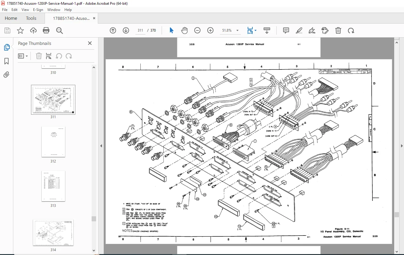
Manual PDF Quality: High quality scan with clear text, block diagrams, and schematics.
No. of Pages: 354 (Digital page count)
What Our Customers Say
🌟 Related Products
Discover more professional manuals for your equipment
Acuson Aspen Ultrasound Service Manual PDF - DIMAQ System Repair Guide