Acuson Aspen Ultrasound Service Manual PDF – DIMAQ System Repair Guide
Original price was: $80.00.$28.95Current price is: $28.95.
Official Acuson Aspen Ultrasound System Service Manual (Part #49881) for complete maintenance, repair, and troubleshooting of DIMAQ integrated ultrasound workstation. This comprehensive Acuson Aspen ultrasound service manual covers system architecture, scanner assemblies, power subsystems, 2D/M-mode/Color Doppler data paths, and field replaceable unit (FRU) replacement procedures.
Essential DIMAQ ultrasound workstation repair guide for biomedical technicians performing medical imaging equipment maintenance. 230 pages with detailed theory of operation, diagnostics, preventive maintenance procedures.
Description
Acuson Aspen Ultrasound Service Manual PDF – DIMAQ System Repair Guide PDF DOWNLOAD
IMAGES:
Description
Acuson Aspen Ultrasound System Service Manual – Complete DIMAQ Workstation Repair Documentation
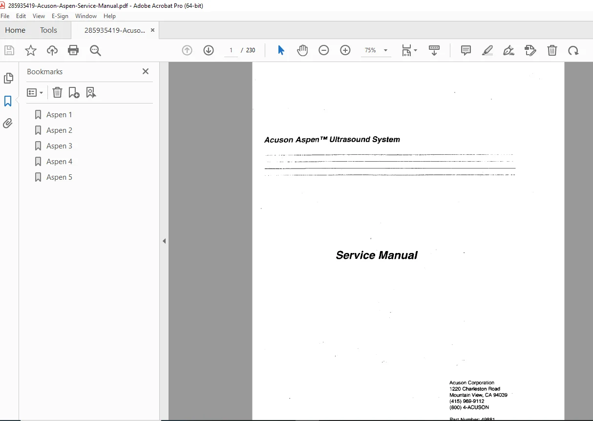
When your Acuson Aspen ultrasound system requires professional service, calibration, or component replacement, you need the official factory documentation. This is the Official Acuson Aspen Ultrasound System Service Manual (Part Number 49881) – the exact technical guide that certified biomedical equipment technicians (BMETs) and authorized Acuson service personnel use for comprehensive medical imaging equipment maintenance. This essential Acuson Aspen ultrasound service manual provides complete coverage of the DIMAQ (Digital Imaging and Acquisition) integrated ultrasound workstation.
Complete Coverage for Acuson Aspen Ultrasound System
This DIMAQ ultrasound workstation repair guide provides detailed technical documentation for the complete Acuson Aspen mobile ultrasound system, including:
- DIMAQ Integrated Ultrasound Workstation (complete architecture)
- Scanner Assemblies (transmit/receive circuitry)
- Power Subsystem (distribution and supplies)
- Scan Converter (image processing)
- Monitor Assembly (display system)
- User Interface (control panel and peripherals)
- AEGIS System (image optimization)
- ECG and Physio Signal Processing
Comprehensive System Architecture Documentation
One of the key strengths of this manual is the complete coverage of the Acuson Aspen system architecture with detailed ultrasound scanner assembly replacement procedures and theory of operation for all major subsystems.
Ultrasound Imaging Modes Covered:
- 2D (B-Mode) Imaging – Real-time grayscale imaging data path
- M-Mode Imaging – Motion mode for cardiac applications
- Spectral Doppler – Blood flow velocity analysis
- Color Doppler – Color flow mapping and velocity imaging
- Convergent Color Doppler (CDE/CDV) – Advanced color imaging
DIMAQ Workstation Components:
- Digital signal processing architecture
- Image acquisition and storage
- Cine memory operation
- Multi-format display capabilities
- Network connectivity (optional)
- Peripheral interface systems
What Makes This Service Manual Essential
Factory-Level Technical Documentation
- Official Acuson Corporation engineering specifications
- Complete theory of operation for all assemblies
- Professional Acuson ultrasound system troubleshooting procedures
- Detailed block diagrams and signal flow
- Component-level repair information for color Doppler ultrasound service
Field Replaceable Unit (FRU) Procedures
This manual excels in providing step-by-step procedures for removing and replacing major system components:
- Scan Converter Assembly (digital image processing)
- Scanner Assembly (ultrasound transmitter/receiver)
- Power Subsystem (multiple power supplies)
- Monitor Assembly (CRT display system)
- User Interface (control panel and trackball)
- Isolation Transformer Box (electrical safety)
- Printed Circuit Boards (all major PCBs)
Each FRU procedure includes:
- Required tools and test equipment
- Detailed disassembly steps with photos
- Component identification and location
- Reassembly procedures
- Post-replacement verification tests
Comprehensive Troubleshooting
- Symptom-based diagnosis flowcharts
- Quick tips for common problems
- System-level troubleshooting procedures
- Customer diagnostics menu access
- Emergency diagnostics bypass
- Technical assistance guidelines
📋 Complete Manual Contents
Official Acuson Service Manual (230 Pages)
Preface (Pages xi-xv)
About This Manual
- Manual purpose and scope
- Target audience (trained service personnel)
- Required technical background
- Safety warnings and precautions
Organization
- Chapter-by-chapter overview
- Manual structure explanation
- How to use this manual effectively
Other Aspen System Manuals
- Acuson Aspen General Applications User Manual with Cardiac Option
- Standard and optional features
- Operating procedures
- Clinical applications
- Acuson Aspen Transducer and Peripherals Manual with Cardiac Option
- Transducer specifications
- Biopsy procedures
- Peripheral device setup and operation
- Power value tables
Contacting Acuson
- Acuson Corporation contact information
- Technical support resources
- Parts ordering procedures
- Service center locations
Chapter 1: Introduction and System Requirements (Pages 1-1 to 1-15)
Introduction to the Aspen System (Page 1-2)
- System Overview:
- Mobile, self-contained ultrasound system
- DIMAQ integrated workstation
- Advanced imaging capabilities
- Cardiac and general applications
- Figure 1-1: Aspen System – Front View
- System layout and components
- User interface location
- Monitor positioning
- Transducer connectors
Reviewing System Requirements (Pages 1-4 to 1-8)
Table 1-1: Input Power Values for Aspen System
| Parameter | Specification |
|---|---|
| Input Voltage | 100-240 VAC |
| Frequency | 50/60 Hz |
| Power Consumption | 800 VA typical |
| Power Factor | >0.95 |
- Electrical Requirements:
- Power input specifications
- Circuit breaker requirements
- Grounding requirements
- Electrical safety considerations
- Environmental Requirements:
- Operating temperature range
- Storage temperature range
- Humidity specifications
- Altitude limitations
- Physical Specifications:
- Dimensions (H x W x D)
- Weight specifications
- Clearance requirements
- Mobility considerations
Using Input and Output Connectors (Pages 1-8 to 1-11)
Table 1-2: Aspen System Rear Input and Output Connectors
| Connector | Type | Function |
|---|---|---|
| AC Power | IEC 320 | Main power input |
| Video Out | BNC | Analog video output |
| S-Video | 4-pin Mini-DIN | High-quality video |
| RGB | 15-pin D-sub | Computer monitor |
| ECG | 9-pin D-sub | ECG signal input |
| Printer | 25-pin D-sub | Parallel printer |
| Network | RJ-45 | Ethernet (optional) |
| RS-232 | 9-pin D-sub | Serial communication |
| Footswitch | 6-pin | Remote control |
- Figure 1-4: Aspen System Rear Panel Connectors
- Connector locations and labels
- Cable routing considerations
- Peripheral connections
Table 1-3: Aspen System Front Panel Input and Output Connectors
| Connector | Function |
|---|---|
| Transducer Ports (4) | Ultrasound probe connections |
| Audio Output | Doppler audio monitoring |
| VCR In/Out | Video recording interface |
| Headphone Jack | Private audio monitoring |
- Figure 1-5: Aspen System Front Panel Connectors
- User-accessible connections
- Transducer port layout
Identifying PCB Type, Version, and Revision (Page 1-11)
- Figure 1-6: Aspen System PCB
- Circuit board identification
- Version marking locations
- Revision code explanation
- Date code interpretation
Following Basic Precautions (Page 1-12)
- Safety Warnings:
- High voltage hazards (CRT, power supplies)
- ESD sensitive components
- Electrical shock prevention
- Proper grounding requirements
- Service Precautions:
- System must be powered off
- Discharge procedures
- Component handling
- Tool requirements
Caring for the System (Pages 1-12 to 1-14)
- Cleaning Procedures:
- Approved cleaning agents
- Surface cleaning protocols
- Disinfection procedures (Cidex, Metricide, etc.)
- Control panel cleaning
- Maintenance Guidelines:
- Daily inspection items
- Weekly maintenance tasks
- Monthly checks
- Annual preventive maintenance
Caring for Transducers (Pages 1-14 to 1-15)
- Transducer cleaning procedures
- Disinfection protocols
- Storage requirements
- Cable handling
- Damage prevention
Moving the System (Page 1-15)
- Pre-move checklist
- Locking casters
- Cable management
- Transducer protection
- Safe transport procedures
Attaching Peripherals (Page 1-15)
- Printer connection
- VCR setup
- ECG connection
- Network setup (if applicable)
- Footswitch installation
Chapter 2: System Architecture (Pages 2-1 to 2-36)
Ultrasound Basics (Pages 2-3)
- Ultrasound physics fundamentals
- Piezoelectric effect
- Pulse-echo principle
- Image formation theory
- Resolution concepts
System Architecture (Pages 2-3 to 2-6)
- Overall system block diagram
- Major subsystem interconnections
- Data flow overview
- Control signal paths
Theory of Operation (Pages 2-6 to 2-11)
- System Operation Overview:
- Transmit pulse generation
- Echo reception and processing
- Signal amplification
- Analog-to-digital conversion
- Digital signal processing
- Image formation and display
Scanner Assemblies (Pages 2-11 to 2-20)
- Transmitter Section:
- Pulse generation circuits
- High-voltage transmit amplifiers
- Beam forming and focusing
- Transmit/receive switching
- Receiver Section:
- Low-noise preamplifiers
- Time-gain compensation (TGC)
- Dynamic range compression
- Beam forming and apodization
- RF signal processing
- Transducer Interface:
- Multi-element transducer control
- Impedance matching
- Protection circuits
- Connector specifications
DIMAQ Integrated Ultrasound Workstation (Pages 2-20 to 2-23)
- DIMAQ Architecture:
- Digital signal processor (DSP) architecture
- Memory subsystems
- Image processing pipeline
- Display interface
- Storage subsystems
Theory of Operation (Page 2-23)
- DIMAQ processing flow
- Real-time operation
- Cine buffer management
- Measurement calculations
2D Data Path (Pages 2-23 to 2-25)
- B-Mode Imaging:
- RF signal demodulation
- Envelope detection
- Log compression
- Scan conversion
- Image optimization
- Display mapping
Spectral Doppler Data Path (Pages 2-25 to 2-27)
- Doppler Processing:
- Doppler shift detection
- Fast Fourier Transform (FFT)
- Spectral display generation
- Velocity scale calculation
- Audio signal generation
Color Doppler Data Path (Pages 2-27 to 2-29)
- Color Flow Mapping:
- Multi-gate Doppler processing
- Autocorrelation technique
- Velocity estimation
- Convergent Color Doppler (CDE/CDV)
- Color priority and persistence
- 2D/Color overlay
M-mode Data Path (Pages 2-29 to 2-31)
- Motion Mode:
- Single scan line extraction
- Time-motion display
- Simultaneous 2D display
- Measurement capabilities
Cine Operation (Page 2-31)
- Cine memory architecture
- Cine buffer allocation
- Review and playback
- Cine storage and retrieval
AEGIS System (Pages 2-31 to 2-33)
- Adaptive Edge-Enhancement Grayscale Imaging System:
- Image optimization algorithms
- Edge enhancement
- Noise reduction
- Tissue-specific processing
ECG and Physio Signal Processing (Pages 2-33 to 2-34)
- ECG signal acquisition
- QRS detection
- Trigger generation
- Physio signal display
- Cardiac gating
Audio (Page 2-34)
- Doppler audio generation
- Audio amplification
- Speaker and headphone outputs
- Volume control
DIMAQ Workstation Assemblies (Pages 2-36)
- Physical component layout
- Board locations
- Interconnection scheme
- Cooling system
Chapter 3: Power Subsystem (Pages 3-1 to 3-14)
Power Supply Architecture (Pages 3-2 to 3-3)
- Power Distribution Overview:
- AC input and filtering
- Primary power supplies
- Secondary voltage regulators
- Power-on sequencing
- Protection circuits
- Voltage Rails:
- +5V digital logic
- +12V / -12V analog circuits
- High-voltage supplies (CRT, transmit)
- Isolated supplies
- Power consumption by subsystem
Isolation Transformer Box (Pages 3-3 to 3-10)
- Isolation Transformer Function:
- Electrical isolation for patient safety
- Common-mode noise rejection
- Leakage current limitation
- Safety standards compliance (IEC 60601)
- Theory of Operation:
- Transformer specifications
- Input filtering
- Output regulation
- Thermal management
- Test Points and Measurements:
- Input voltage verification
- Output voltage testing
- Leakage current measurement
- Ground integrity testing
Power Subsystem Theory of Operation (Pages 3-10 to 3-14)
- Main Power Supply:
- Switching power supply topology
- Voltage regulation
- Current limiting
- Over-voltage protection
- Over-temperature protection
- Figure 3-3: Aspen System Power On/Off Sequence
- Power-up sequence diagram
- Voltage rail timing
- Enable signal sequencing
- Power-down sequence
- Power Distribution:
- Power bus architecture
- Fusing and protection
- Distribution to assemblies
- Power monitoring
Power Sub Assemblies (Page 3-14)
- Individual power supply modules
- Specifications for each supply
- Replacement procedures
- Testing and verification
Chapter 4: Removing and Replacing Field Replaceable Units (FRUs) (Pages 4-1 to 4-20)
This comprehensive chapter provides detailed step-by-step procedures for accessing, removing, and replacing all major Field Replaceable Units in the Aspen system.
Introduction to Removing and Replacing FRUs (Pages 4-3 to 4-5)
- General Procedures:
- Safety precautions (CRITICAL)
- Required tools list
- ESD protection requirements
- System power-down procedures
- Cable labeling and documentation
- Figure 4-1: Aspen System – Front View
- Component access points
- Panel removal sequence
- Figure 4-2: Aspen System – Rear View
- Rear panel component locations
- Cable routing
Scan Converter (Pages 4-5 to 4-10)
- Location and Function:
- Scan converter PCB location
- Image processing functions
- Interface connections
- Removal Procedure:
- Power down system and disconnect AC
- Remove rear panel (4 screws)
- Document cable connections
- Disconnect interface cables
- Remove mounting screws
- Extract scan converter assembly
- Installation Procedure:
- Position new scan converter
- Install mounting screws
- Reconnect all cables per documentation
- Replace rear panel
- Power on and verify operation
- Verification Tests:
- Image display check
- Scan converter self-test
- Image quality verification
- Measurement accuracy check
Scanner (Pages 4-10 to 4-15)
- Scanner Assembly Overview:
- Transmitter circuits
- Receiver circuits
- T/R switching
- Beam former
- Removal Procedure:
- Detailed step-by-step instructions
- Cable disconnection sequence
- Mounting hardware removal
- Assembly extraction
- Installation:
- Assembly positioning
- Hardware installation
- Cable reconnection
- Functional verification
- Post-Installation Tests:
- Transmit pulse verification
- Receive sensitivity check
- Image quality assessment
- System diagnostics
Power Subsystem (Pages 4-15 to 4-19)
- Individual Power Supply Replacement:
- Main supply
- Scanner supply
- Display supply
- Logic supply
- Each Supply Procedure Includes:
- Location identification
- Voltage verification before removal
- Mounting removal
- Connector disconnection
- New supply installation
- Output voltage verification
- Load testing
Monitor Assembly (Pages 4-19 to 4-20)
- CRT Display Replacement:
- HIGH VOLTAGE WARNING
- CRT discharge procedures (MANDATORY)
- Neck board removal
- CRT mounting removal
- Yoke removal
- New CRT installation
- Convergence and geometry setup
- Monitor Board Replacement:
- Video input board
- Deflection circuits
- High-voltage supply
- Installation and adjustment
User Interface (Page 4-20)
- Control Panel Assembly:
- Control panel removal
- Keyboard replacement
- Trackball service
- Soft keys and switches
- LED indicators
- Figure 4-7: View of IOB from the Rear of Aspen System
- Interconnect board access
- Component identification
Chapter 5: Troubleshooting (Pages 5-1 to 5-6)
System Troubleshooting (Page 5-2)
- Systematic approach to fault diagnosis
- Initial checks and observations
- Isolation techniques
- Component-level troubleshooting
Technical Assistance (Pages 5-2 to 5-3)
- When to contact Acuson technical support
- Information to gather before calling
- Support contact procedures
- Remote diagnostics capabilities
Symptom Type (Page 5-5)
- Symptom classification system
- Power-related symptoms
- Display problems
- Image quality issues
- Operational problems
- Peripheral device issues
Quick Tips (Page 5-6)
- Common quick fixes
- User error vs. hardware fault
- Simple checks before component replacement
- Reset procedures
Common Symptoms and Fixes (Pages 5-6 to end of chapter)
Table: Troubleshooting Guide
| Symptom | Possible Cause | Corrective Action |
|---|---|---|
| No Power | AC input failure | Check power cord, circuit breaker |
| Power supply fault | Test voltages, replace PSU | |
| No Display | Monitor failure | Check monitor power, replace if needed |
| Video board fault | Check video signals, replace board | |
| No Image | Transducer failure | Test with known good transducer |
| Scanner fault | Run diagnostics, check transmit/receive | |
| Poor Image Quality | Transducer damage | Inspect transducer, replace if needed |
| Receiver problems | Check TGC, gain settings | |
| Processing issues | Run image quality tests | |
| No Doppler | Doppler board fault | Check audio output, run diagnostics |
| Software issue | Reboot, check settings | |
| Keyboard/Trackball Issues | User interface fault | Clean contacts, replace if needed |
| Ribbon cable | Check connections |
Chapter 6: System Diagnostics (Pages 6-1 to 6-6)
Accessing Customer Menu (Page 6-2)
- Menu Access Procedure:
- Special key sequence
- Password requirements (if applicable)
- Menu navigation
- Exiting diagnostics
The Customer Menu (Pages 6-2 to 6-6)
- Available Diagnostic Tests:
- Display Tests:
- Color bars
- Gray scale ramp
- Convergence patterns
- Geometry patterns
- System Tests:
- Memory test
- Disk drive test
- Printer test
- Network test
- Image Quality Tests:
- Resolution test patterns
- Dynamic range verification
- Noise measurement
- Uniformity tests
- Transducer Tests:
- Element functionality
- Transmit verification
- Receive sensitivity
- Doppler Tests:
- Spectral Doppler verification
- Color Doppler test
- Audio output test
- Display Tests:
- Test Result Interpretation:
- Pass/fail criteria
- Error code meanings
- Next steps for failures
Emergency Diagnostics Bypass (Page 6-6)
- When to use bypass mode
- Bypass access procedures
- Limited functionality operation
- Restoring normal operation
Technical Assistance (Page 6-6)
- Diagnostic result reporting
- Remote assistance procedures
- Log file generation and transmission
Chapter 7: Preventive Maintenance (Pages 7-1 to 7-11)
Preventive Maintenance (Pages 7-2)
- Importance of regular maintenance
- Recommended maintenance intervals
- Documentation requirements
- Parts replacement schedule
Preliminaries (Page 7-2)
- Required tools and test equipment
- Safety precautions
- System preparation
- Record keeping
Visual Inspection (Pages 7-2 to 7-3)
- Exterior Inspection:
- Case damage assessment
- Control panel condition
- Cable integrity
- Caster and lock function
- Interior Inspection:
- Dust accumulation
- Component condition
- Solder joint integrity
- Connector security
Mechanical Inspection (Pages 7-3 to 7-5)
- Moving Parts:
- Trackball operation
- Switch function
- Keyboard keys
- Control knobs
- Cooling fans
- Mounting Hardware:
- Tightness verification
- Bracket integrity
- PCB mounting
Electrical Verification (Pages 7-5 to 7-6)
- Voltage Measurements:
- Power supply outputs
- Voltage regulation
- Ripple measurements
- Leakage Current Test:
- Patient safety verification
- IEC 60601 compliance
- Ground integrity
System Monitor Controls (Pages 7-6 to 7-7)
- Monitor convergence check
- Focus verification
- Brightness and contrast
- Geometry adjustment
- Color purity
Operational Verification (Pages 7-7 to 7-8)
- Imaging Tests:
- 2D image quality
- M-mode operation
- Spectral Doppler
- Color Doppler
- Measurement Accuracy:
- Distance calibration
- Velocity calibration
- Area measurements
- Peripheral Function:
- Printer operation
- VCR recording
- ECG input
- Network connectivity
Customer Diagnostics (Pages 7-8 to 7-11)
- Running full diagnostic suite
- Recording test results
- Performance verification
- Documentation and certification
Chapter 8: Parts List (Pages 8-1 to 8-10)
Aspen System Acronym List (Page 8-2)
| Acronym | Definition |
|---|---|
| AEGIS | Adaptive Edge-Enhancement Grayscale Imaging System |
| CDE | Convergent Doppler Energy |
| CDV | Convergent Doppler Velocity |
| CRT | Cathode Ray Tube |
| DIMAQ | Digital Imaging and Acquisition |
| DSP | Digital Signal Processor |
| ECG | Electrocardiogram |
| FFT | Fast Fourier Transform |
| FRU | Field Replaceable Unit |
| I/O | Input/Output |
| IOB | Input/Output Board |
| PCB | Printed Circuit Board |
| RF | Radio Frequency |
| TGC | Time Gain Compensation |
| T/R | Transmit/Receive |
Aspen System Parts List (Pages 8-4)
- How to use the parts list
- Part number format
- Ordering procedures
- Availability information
Cables and Wire Harnesses (Pages 8-4 to 8-6)
| Part Number | Description | Application |
|---|---|---|
| Cable assemblies for power distribution | – | – |
| Signal cables (video, control, data) | – | – |
| Transducer cables | – | – |
| Peripheral interface cables | – | – |
Chassis Hardware (Page 8-6)
- Screws, nuts, washers
- Mounting brackets
- Covers and panels
- Handles and latches
Monitor Assembly (Page 8-8)
- CRT (specify size and type)
- Monitor boards
- CRT socket
- Deflection yoke
- High-voltage components
Peripheral Interface Cable Assemblies (Page 8-8)
- Printer cables
- VCR cables
- ECG cables
- Network cables
- RS-232 cables
Power Supplies (Page 8-8)
- Main power supply
- Scanner power supply
- Display power supply
- Logic power supply
- Specifications for each
Printed Circuit Boards (Pages 8-9)
- Scan converter board
- Scanner transmitter board
- Scanner receiver board
- Video processor board
- User interface board
- I/O board
- All with part numbers and revisions
Misc. Parts (Page 8-10)
- Fuses (all types and ratings)
- Connectors
- Switches
- Potentiometers
- Capacitors
- Transducers (reference only)
User Interface Assemblies (Page 8-10)
- Control panel assembly
- Keyboard
- Trackball
- Soft keys
- Rotary encoders
- LEDs
Appendix A: System Drawings (Pages A-1 to end)
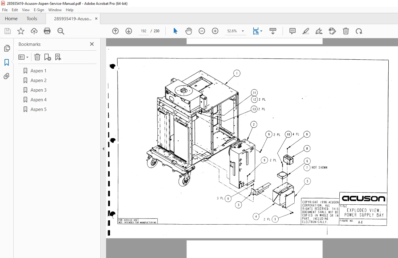
- Complete exploded view diagrams
- Component identification
- Assembly relationships
- Hardware specifications
- Mechanical drawings
Appendix B: Warranty and Service (Pages B-1 to B-6)
Warranty and Limitations of Liability (Pages B-2 to B-6)
- Standard warranty coverage
- Warranty period
- What is covered
- Warranty exclusions
- Limitations of liability
- Disclaimer of warranties
Preventive Maintenance (Page B-6)
- Warranty maintenance requirements
- Recommended PM schedule
- Documentation for warranty
Customer Service (Page B-6)
- Service contact information
- Service request procedures
- Parts ordering
- Technical support hours
Index (Last pages)
- Comprehensive alphabetical index
- Cross-references
- Page numbers for all topics
📄 File Details
- Manual Name: Acuson Aspen Ultrasound System Service Manual
- Part Number: 49881
- Models Covered:
- Acuson Aspen Ultrasound System
- DIMAQ Integrated Ultrasound Workstation
- All Aspen system configurations with cardiac option
- Publication Date: First Edition October 1996
- Copyright: 1996 Acuson Corporation
- Related Systems:
- Not for Model 128 (use P/N 19018 or 23151)
- Not for 128XP (use P/N 25997)
- Not for Sequoia 512 (use P/N 49726)
- Not for Sequoia C256 (use P/N 48135)
- PDF Quality: Good quality scan from original manual, searchable text, includes all diagrams and tables
- Pages: 230
- Language: English
- File Size: 20.3 MB
- Format: PDF 1.3
Who Needs This Manual?
This official Acuson service manual is essential for:
- Biomedical Equipment Technicians (BMETs) – Hospital equipment maintenance
- Clinical Engineering Departments – In-house ultrasound service
- Acuson Authorized Service Centers – Factory-level repair capability
- Medical Equipment Service Companies – Third-party service providers
- Imaging Department Technical Staff – Basic troubleshooting and maintenance
- Radiology Service Engineers – Multi-modality equipment support
- Ultrasound Equipment Specialists – Dedicated ultrasound service technicians
- Hospital Biomedical Engineering Programs – Training and education
- Military/VA Medical Centers – Government equipment sustainment
What Makes the Acuson Aspen Special
The Acuson Aspen represents professional-grade portable ultrasound technology:
- DIMAQ Digital Workstation – Advanced digital signal processing
- Multi-Mode Imaging – 2D, M-mode, Spectral Doppler, Color Doppler
- AEGIS Technology – Adaptive edge enhancement and image optimization
- Convergent Color Doppler – Advanced color flow imaging (CDE/CDV)
- Cardiac Applications – Comprehensive echocardiography capabilities
- General Imaging – Abdominal, OB/GYN, vascular, small parts
- Mobile Design – Full-featured portable system
- Multi-Frequency Transducers – MultiHertz technology
- Digital Cine – Image loop review and storage
- ECG Integration – Cardiac gating and synchronization
Why This Service Manual is Critical
Factory-Level Repair Capability:
- Official Acuson Corporation engineering documentation (not third-party)
- Complete Acuson ultrasound system troubleshooting procedures
- Component-level repair information for DIMAQ ultrasound workstation repair
- Theory of operation for understanding system function
- Professional medical imaging equipment maintenance procedures
Comprehensive System Architecture:
- Detailed block diagrams and signal flow
- Scanner assembly operation (transmit/receive)
- Color Doppler ultrasound service procedures
- Digital signal processing architecture
- DIMAQ workstation detailed operation
Complete FRU Replacement Procedures:
- All major ultrasound scanner assembly replacement procedures
- Step-by-step disassembly instructions
- Cable routing documentation
- Post-replacement verification tests
- Parts identification and ordering
Prevent Costly Mistakes:
- Correct disassembly sequences prevent damage
- Proper ESD handling protects sensitive electronics
- Power-on sequence requirements prevent failures
- Safety procedures protect patients and technicians
- Diagnostic procedures identify problems accurately
Common Service Scenarios Covered:
✅ No Power – Power supply troubleshooting and replacement
✅ No Display – Monitor assembly and video board diagnosis
✅ Poor Image Quality – Scanner calibration and adjustment
✅ No Doppler Signal – Doppler processor and audio troubleshooting
✅ Transducer Not Recognized – Interface and connector diagnosis
✅ Control Panel Malfunction – User interface repair and replacement
✅ No ECG Signal – ECG input troubleshooting
✅ Printer Problems – Peripheral interface diagnosis
✅ System Crashes – DIMAQ workstation troubleshooting
✅ Color Doppler Issues – Color processing board service
✅ Cine Memory Errors – Memory system diagnosis
✅ Network Connectivity – Communication interface troubleshooting
⚠️ Important Notice
This is a professional-grade factory service manual intended for qualified biomedical equipment technicians and trained service personnel with experience in medical imaging equipment repair. Working on ultrasound systems requires knowledge of:
- Medical electrical safety (IEC 60601 standards)
- High-voltage circuits (CRT display, transmit circuits)
- ESD-sensitive medical electronics
- Ultrasound physics and technology
- Patient safety requirements
- Regulatory compliance (FDA, CE marking)
CRITICAL SAFETY WARNING: Lethal voltages are present inside the Acuson Aspen ultrasound system. Bodily harm, possibly death, as well as damage to the system may result from untrained individuals opening the system. This manual is intended for use by trained service personnel only.
Always follow safety procedures, including:
- Proper system power-down and lockout
- ESD precautions for all circuit boards
- High-voltage discharge procedures (CRT)
- Patient leakage current testing after service
- Electrical safety analyzer verification
Regulatory Note: After any service that could affect patient safety (power supplies, patient cables, ECG inputs), electrical safety testing must be performed per IEC 60601-1 to verify compliance with medical device safety standards.
Key Benefits:
✅ Official Acuson Factory Documentation – Authentic service procedures
✅ Complete DIMAQ Workstation Coverage – Digital imaging system details
✅ 230 Pages of comprehensive technical information
✅ All Imaging Modes Covered – 2D, M-mode, Spectral and Color Doppler
✅ Scanner Assembly Details – Transmit/receive circuit documentation
✅ Field Replaceable Unit Procedures – Complete FRU replacement
✅ System Architecture – Block diagrams and theory of operation
✅ Troubleshooting Procedures – Symptom-based diagnosis
✅ Customer Diagnostics – Built-in test procedures
✅ Preventive Maintenance – Complete PM checklist
✅ Complete Parts List – Accurate parts identification and ordering
✅ Exploded View Diagrams – Visual assembly relationships
✅ Electrical Safety – Leakage current and grounding tests
✅ Searchable PDF – Find information quickly
✅ Instant Download – Start service work immediately
Maintain Critical Diagnostic Equipment
The Acuson Aspen ultrasound system is professional-grade diagnostic imaging equipment used in hospitals, clinics, and medical centers worldwide for cardiac, vascular, obstetric, and general imaging applications. Proper maintenance and timely repair ensure accurate diagnoses, patient safety, and optimal image quality. This service manual provides the factory procedures to keep your Aspen ultrasound system operating at peak performance, extend equipment life, and maintain regulatory compliance.
Whether you’re performing routine preventive maintenance, troubleshooting image quality issues, replacing scanner assemblies, diagnosing power problems, or conducting electrical safety tests, this manual is your essential resource for professional medical imaging equipment maintenance and Acuson ultrasound system troubleshooting.
Instant Digital Delivery: Receive your PDF manual immediately after purchase. No shipping delays, no waiting. Download and start your service work right away.