Acuson 128XP Service Manual Part 2: Power Supply Repair Guide PDF
Original price was: $95.00.$20.95Current price is: $20.95.
Dive into the Acuson 128XP power supply service manual for detailed troubleshooting and repair of ultrasound scanner power systems. This comprehensive guide covers power supply architecture, error codes, wiring diagrams, and power sequences for the Acuson 128XP ultrasound repair manual. Ideal for technicians handling Acuson 128XP service manual part 2 on power distribution, soft-start circuits, and fault diagnosis in medical imaging equipment.
Description
Acuson 128XP Service Manual Part 2: Power Supply Repair Guide – PDF DOWNLOAD
Description
This Acuson 128XP power supply service manual (Part 2) provides in-depth technical information for maintaining and repairing the power supply system of the Acuson 128XP ultrasound scanner. As an essential ultrasound scanner repair guide part 2, it focuses on critical components like the Power Distribution Board 2 (PDB 2), soft-start mechanisms, and voltage regulation to ensure reliable operation under various conditions. Whether you’re diagnosing over-voltage issues or synchronizing supplies with PERCLK, this Acuson 128XP service manual part 2 equips you with diagrams, fault codes, and step-by-step theory for efficient repairs.
Key Sections and Content Overview:
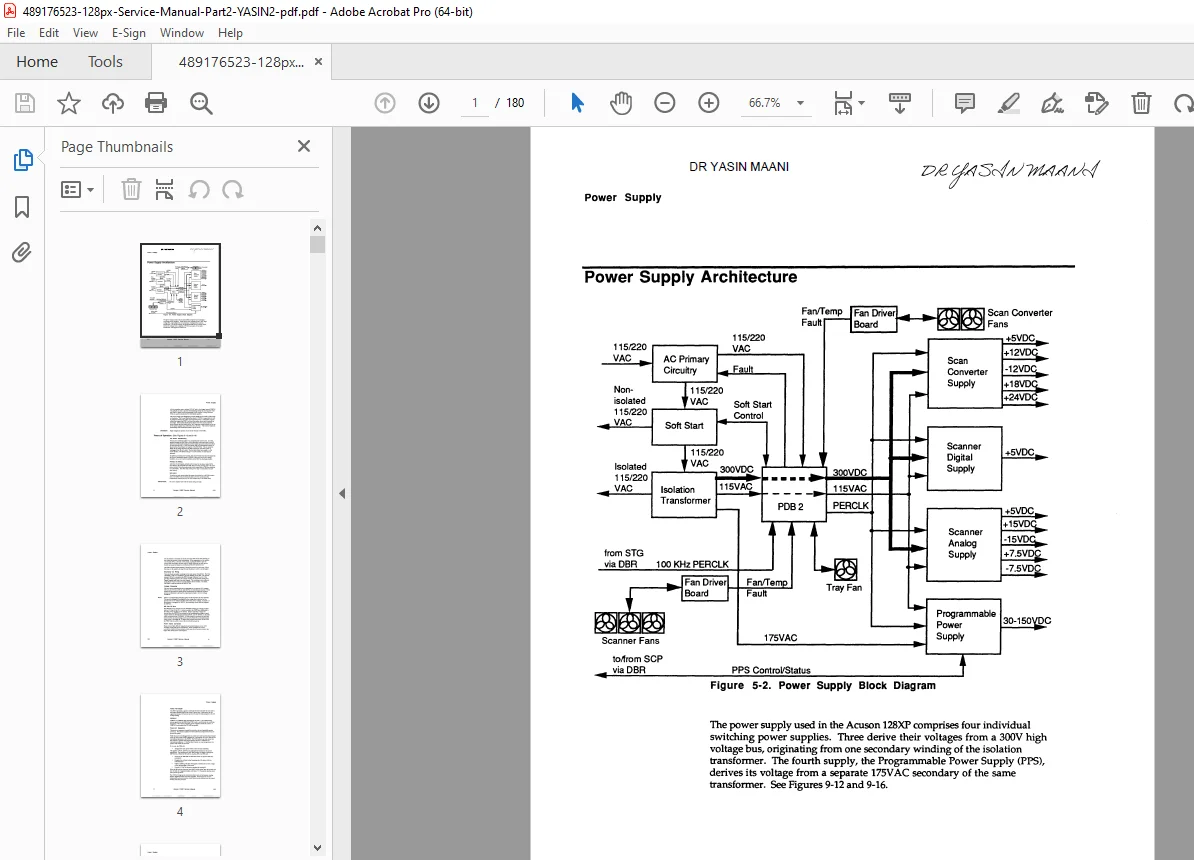
- Power Supply Architecture: Explains the block diagram (Figure 5-2) with four switching power supplies deriving from a 300V bus and 175VAC secondary. Includes synchronization via PERCLK from the Scanner Timing Generator (STG).
- Theory of Operation: Detailed breakdown of AC power conditioning, primary/secondary AC wiring, soft-start circuits (with 3Ω resistor and thermal switch), voltage strapping options (100/115VAC domestic, 220/240VAC international), 300V DC bus, and power factor correction.
- Power Sequences:
- Power-On Sequence: Step-by-step from main switch activation, energizing relays, charging the 300V bus, to enabling the Programmable Power Supply (PPS).
- Power-Off Sequence: Covers fault-triggered shutdowns, pulling power fail (PF) signal low, data saving to battery-backed RAM, and discharging the 300V bus.
- Power Supply Noise Reduction: Techniques including secure scanner top cover, conductive rope grounding, and PERCLK synchronization for minimizing switching noise.
- Power Supply Subassemblies:
- PDB 2 Details: Domestic P/N 18452T, International P/N 18452TI. Includes opto-isolators for leakage reduction, fan driving, and supervisory circuitry.
Error Codes Table (from 7-Segment Display):
| Error | Symptom |
|---|---|
| 1 | Low AC line voltage (<95VAC) |
| 2 | Low 300V Bus (<250VDC) |
| 3 | High 300V Bus (>360VDC) |
| 4 | Scan Converter power supply – fault |
| 5 | Power Supply Tray – over-temperature or fan fault |
| 6 | Scanner – over-temperature or fan fault |
| 7 | Scan Converter – over-temperature or fan fault |
| 8 | Scanner Digital 5V power supply – fault |
| 9 | Scanner Low Voltage power supply – fault |
| . | Accompanies a 1 or 2 error and denotes that the error was encountered during power-up |
Fuses Table:
| Fuses | Rating |
|---|---|
| F1 | 2A |
| F2 | 0.2A (domestic) 0.063A (international) |
Interconnections Table
| PDB Interconnections | Functions |
|---|---|
| Soft-start | Electronically switches main power and soft-start resistor relays; senses resistor temperature. |
| Isolated 115 VAC | Electronically switched; provides control power to supplies. |
| 300 volt bus | Monitors and controls; distributes to supplies. |
| Fan Power | Monitors fan voltage (18V) from Scan Converter supply. |
| PERCLK | Electronically switched; synchronizes power supplies; enables PPS. |
| Power Fail (PF) | Electronically switched; provides power down interrupt to Scan Converter. |
| OVP | Trips main circuit breaker; powered by 300 volt bus. |
| Remote On | Used to power the PDB 2 and close the Power Relay during hipot testing. |
Jumpers Table:
| Jumper | Comments |
|---|---|
| W1 | Bypasses the fan-power error power-off interlock. |
| W2 | Bypasses all error power-off interlocks. |
| W3 | Tests OVP trip of main circuit breaker. |
| W7 | Removed for use with speed sensing fans. |
Warnings and Notes:
- DANGER! High voltages present on PDB 2.
- IMPORTANT: Replace fuses with same rating/type.
- WARNING: Measure leakage current after replacing PDB 2.
- Note: Test secondary OVP by jumpering W3; ensure circuit breaker trips.
This ultrasound scanner repair guide part 2 also includes figures like Power Supply Block Diagram (Figure 5-2) and Power Distribution Board 2 (Figure 5-3), making it a vital resource for Acuson 128XP ultrasound repair manual users.
File Details:
- Manual Name: Acuson 128XP Service Manual Part 2 – Power Supply
- Models Covered: Acuson 128XP Ultrasound System
- Year: Not specified (vintage technical manual, circa 1990s based on content)
- Manual PDF Quality: High-resolution scanned document with clear text and diagrams
- No. of Pages: 180
Unlock expert-level repairs for your Acuson 128XP with this indispensable power supply service manual—download instantly and get your ultrasound system back to peak performance today!