Description
Airbus A318 A319 A320 A321 Chapter 27 Flight Controls Aircraft Maintenance Manual PDF
This is the complete Airbus A318/A319/A320/A321 Chapter 27 Flight Controls Aircraft Maintenance Manual, issued by AES at Revision 40 (May 01/12). It is the manufacturer-format maintenance chapter dedicated entirely to the fly-by-wire flight control system shared across the A320 Family, covering everything from the side stick controllers in the cockpit to the servocontrols, actuators and computers that move every aileron, rudder, elevator, spoiler, flap and slat on the aircraft. If you maintain, troubleshoot or study A320 Family aircraft, this Chapter 27 Flight Controls manual is the primary reference for that system.
File Details
- Manual type: Aircraft Maintenance Manual (AMM), Chapter 27 – Flight Controls
- Applicable aircraft: Airbus A318, A319, A320, A321
- Publisher/format code: AES
- Revision: Revision n° 40
- Issue date: May 01/12
- Language: English
- Page count: 3,861 pages
- File format: PDF, instant digital download
Chapters Covered
This Chapter 27 Flight Controls Aircraft Maintenance Manual is organized into the full set of A320 Family flight control subsystems, including:
- 27-00-00 Flight Controls – General (description and operation, cockpit control and indicating, electrical/hydraulic power supply, control law implementation, maintenance practices)
- 27-10/14 Aileron and Aileron Hydraulic Actuation (servocontrols, check valve, deactivation/reactivation, adjustment/test, removal/installation, inspection/check)
- 27-20/26 Rudder, Rudder Mechanical Control, Rudder Trim Actuation, Artificial Feel and Rudder Travel Limiting, Rudder Hydraulic Actuation, Rudder Position Indicating, Yaw Damper Actuation
- 27-30/34 Elevator and Elevator Hydraulic Actuation (servocontrols, hydraulic filter, removal/installation, inspection/check)
- 27-40/45 Trimmable Horizontal Stabilizer (THS) – mechanical control, pitch trim control mechanism, drive shaft, THS hydraulic actuation, THS actuator, motor and brake, THS position indicating
- 27-50/55 Flaps – electrical control and monitoring, Slat and Flap Control Computer (SFCC), flaps hydraulic actuation and power transmission, Power Control Unit (PCU), inboard/outboard flap, flaps position indicating
- 27-60/64 Spoiler and Spoiler Hydraulic Actuation (Spoilers 1 through 5, servocontrol, check valve)
- 27-80/85 Lift Augmenting – Slats electrical control and monitoring, slats hydraulic actuation and power transmission, gearboxes, torque shafts, slat tracks 1 through 5, slats position indicating
- 27-90/96 Electrical Flight Control System (EFCS) – control inputs interface and power supply, Elevator Aileron Computer (ELAC), Spoiler Elevator Computer (SEC), Flight Control Data Concentrator (FCDC), side stick assembly, maintenance and safety tests/BITE
Across these sections the manual gives the technician everything needed to work on the A320 Family flight control system: system description and operation narrative, deactivation/reactivation procedures, adjustment and rigging instructions, functional and operational test procedures, removal and installation procedures for every major line-replaceable unit, and inspection/check procedures with wear limits and clearances.
Flight Control System Architecture
The manual opens each major surface section with a plain-language description of how that surface is controlled before moving into hands-on maintenance data. It explains how the fly-by-wire architecture is built around two Elevator Aileron Computers (ELAC), three Spoiler Elevator Computers (SEC), two Flight Control Data Concentrators (FCDC) and the dual Flight Augmentation Computers (FAC), and how roll, pitch and yaw control laws – normal law, alternate law and direct law – are implemented and how authority is redistributed across the ailerons, spoilers, elevators, THS and rudder if a computer or hydraulic system is lost. It covers the redundancy and dissimilarity built into the EFCS, including the different hardware, microprocessors and software between ELAC and SEC computer types, and the monitoring logic that governs each channel.
The Chapter 27 manual also documents the mechanical backup paths that remain available if electrical control is lost: the rudder pedal linkage that mechanically signals the rudder servocontrols, the centering spring device that holds the rudder input neutral on disconnection, and the THS handwheel drive with its overriding mechanism that gives mechanical control priority over electrical control. Hydraulic power supply routing across the Green, Blue and Yellow systems is documented for each surface, along with the electrical power supply architecture behind the EFCS computers and side stick controllers.
Component-Level Maintenance Data
Component-level procedures are provided down to individual parts across every surface. For the aileron and rudder you get removal, installation, adjustment and inspection procedures for the servocontrols, servovalves, solenoid valves, and LVDT/position transducer units, plus rigging and hinge-bearing play checks. The rudder trim actuator, artificial feel and trim unit, rudder travel limitation unit and yaw damper servoactuators each have their own dedicated maintenance practices, adjustment/test and removal/installation sections. For pitch control, the manual details the elevator servocontrols and their eye-ends, the mode selector valve transducer, and the full THS actuator assembly with its double load-path ball screw, no-back brake and pressure-off brakes, along with the mechanical input drive shaft and pitch trim control mechanism.
Complete PDF Bookmark Tree
Complete Bookmarks
The complete bookmarks in the “Airbus A318 A319 A320 A321 Chapter 27 Flight Controls Aircraft Maintenance Manual PDF” are as follows:
Manual Front Matter
Chapter 05 – TIME LIMITS – MAINTENANCE CHECKS
Chapter 06 – DIMENSIONS AND AREAS
Chapter 07 – LIFTING AND SHORING
Chapter 08 – LEVELING AND WEIGHING
Chapter 09 – TOWING AND TAXIING
Chapter 10 – PARKING, MOORING, STORAGE & RETURN TO SERVICE
Chapter 11 – PLACARDS AND MARKINGS
Chapter 12 – SERVICING
Chapter 20 – STANDARD PRACTICES – AIRFRAME
Chapter 21 – AIR CONDITIONING
Chapter 22 – AUTO FLIGHT
Chapter 23 – COMMUNICATIONS
Chapter 24 – ELECTRICAL POWER
Chapter 25 – EQUIPMENT/FURNISHINGS
Chapter 26 – FIRE PROTECTION
+Chapter 27 – FLIGHT CONTROLSp. 1
Table of Contentsp. 1
+27-00 – FLIGHT CONTROLS – GENERALp. 48
+27-00-00 – FLIGHT CONTROLS – GENERALp. 48
+27-00-00 PB 001 CONF 00 – FLIGHT CONTROLS – GENERAL – DESCRIPTION AND OPERATIONp. 48
Description of Primary Flight Controlsp. 48
Flight Controls Power Supplyp. 53
Cockpit Flight Control And Indicatingp. 54
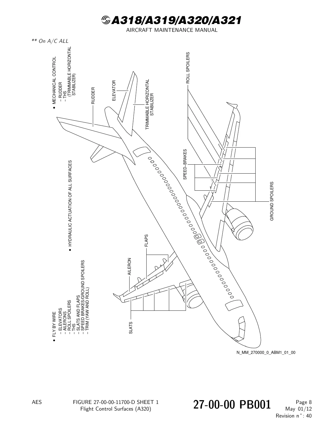
Figure 27-00-00-11700-D – Flight Control Surfaces (A320)p. 55
Figure 27-00-00-13600-B – Electrical Flight Control System Architecturep. 56
Figure 27-00-00-13800-B – Control Law Implementationp. 57
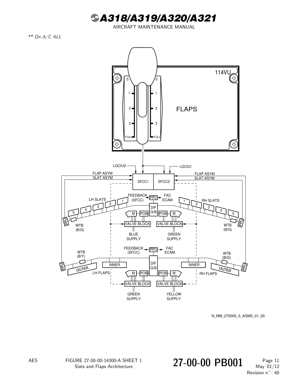
Figure 27-00-00-14300-A – Slats and Flaps Architecturep. 58
Figure 27-00-00-15700-A – Flight Control Electrical Power Supplyp. 59
Figure 27-00-00-16300-B – Flight Control Hydraulic Power Supplyp. 60
Figure 27-00-00-17500-A – Cockpit Control and Indicatingp. 61
+27-00-00 PB 201 CONF 00 – FLIGHT CONTROLS – GENERAL – MAINTENANCE PRACTICESp. 62
+27-00-00-480-001-A – Installation of the Pitch-Trim Control Locking Tool (98D27403500000)p. 62
Figure 27-00-00-991-00100-A – Locking Tool – Pitch-Trim Controlp. 63
27-00-00-080-001-A – Removal of the Pitch-Trim Control Locking Tool (98D27403500000)p. 64
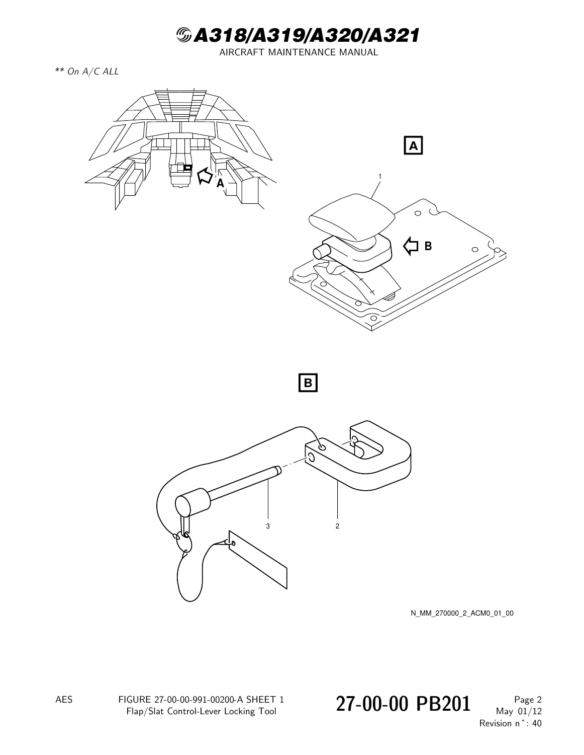
+27-00-00-480-002-A – Installation of the Flap/Slat Control-Lever Locking Tool (98D27803000000)p. 65
Figure 27-00-00-991-00200-A – Flap/Slat Control-Lever Locking Toolp. 66
27-00-00-080-002-A – Removal of the Flap/Slat Control-Lever Locking Tool (98D27803000000)p. 67
+27-10 – AILERONp. 68
+27-10-00 – AILERONp. 68
+27-10-00 PB 001 CONF 00 – AILERON – DESCRIPTION AND OPERATIONp. 68
Generalp. 68
System Descriptionp. 69
Figure 27-10-00-11200-B – Aileron Block Diagramp. 70
+27-14 – AILERON AND HYDRAULIC ACTUATIONp. 71
+27-14-00 – AILERON AND HYDRAULIC ACTUATIONp. 71
+27-14-00 PB 001 CONF 00 – AILERON AND HYDRAULIC ACTUATION – DESCRIPTION AND OPERATIONp. 71
Generalp. 71
Component Locationp. 72
Component Descriptionp. 73
Operationp. 74
Figure 27-14-00-12400-A – Location of Aileron Servocontrolsp. 75
Figure 27-14-00-16300-B – Aileron Servocontrolp. 76
+27-14-00 PB 401 CONF 00 – AILERON AND HYDRAULIC ACTUATION – DEACTIVATION/REACTIVATIONp. 77
+27-14-00-040-001-A – Deactivation of the Aileron Servo Controlp. 77
Figure 27-14-00-991-00200-A – Deactivation/Reactivation of the Aileron Servocontrolp. 81
27-14-00-440-001-A – Reactivation of the Aileron Servo Controlp. 82
+27-14-00 PB 501 CONF 00 – AILERON AND HYDRAULIC ACTUATION – ADJUSTMENT/TESTp. 85
27-14-00-710-001-A – Operational Test of the Aileron and Hydraulic Actuationp. 85
+27-14-00-820-001-A – Adjustment of the Aileronp. 88
Figure 27-14-00-991-00100-A – Position of the Aileron Servocontrolp. 94
Figure 27-14-00-991-00500-A – Aileron Adjustmentp. 95
27-14-00-760-001-A – Electrical Test of the Aileron Servo Controlsp. 96
+27-14-00 PB 601 CONF 00 – AILERON AND HYDRAULIC ACTUATION – INSPECTION/CHECKp. 100
+27-14-00-220-001-A – Check Aileron Servo Controls and Hinge Bearings for Excessive Play and Conditionp. 100
Figure 27-14-00-991-00400-A – Location of the Toolsp. 105
Figure 27-14-00-991-00600-A – CHECK TOOL (DIGITAL) 98D27303022000 (Auto-recording Function)p. 106
+27-14-00-220-002-A – Check of the Aileron Servo Controls Fluid Reserve Piston Position with the Hydraulic Reservoirs Depressurizedp. 107
Figure 27-14-00-991-00300-A – Aileron Servo Controlp. 110
27-14-00-200-001-A – Check of the Aileron Servo Control Oscillationsp. 111
+27-14-41 – AILERONp. 114
+27-14-41 PB 401 CONF 00 – AILERON – REMOVAL/INSTALLATIONp. 114
+27-14-41-000-001-A – Removal of the Aileronp. 114
Figure 27-14-41-991-00100-A – Aileron – Location and Detailp. 118
Figure 27-14-41-991-00200-D – Aileron Attachment – Hinges and Actuatorsp. 119
+27-14-41-400-001-A – Installation of the Aileronp. 121
Figure 27-14-41-991-00400-A – Aileron – Upper and Lower Sealsp. 129
+27-14-41 PB 601 CONF 00 – AILERON – INSPECTION/CHECKp. 130
+27-14-41-200-001-A – Inspection/Check of the Aileronp. 130
Figure 27-14-41-991-00300-C – Aileron Fits and Clearancesp. 136
+27-14-42 – CHECK VALVEp. 137
+27-14-42 PB 401 CONF 00 – CHECK VALVE – REMOVAL/INSTALLATIONp. 137
+27-14-42-000-001-A – Removal of the Check Valvep. 137
Figure 27-14-42-991-00100-A – Check Valve 1626GMp. 140
Figure 27-14-42-991-00200-A – Check Valve 1627GMp. 141
27-14-42-400-001-A – Installation of the Check Valvep. 142
+27-14-51 – SERVO CONTROL – AILERONp. 148
+27-14-51 PB 401 CONF 00 – SERVO CONTROL – AILERON – REMOVAL/INSTALLATIONp. 148
+27-14-51-000-001-A – Removal of the Aileron Servo Controlp. 148
Figure 27-14-51-991-00100-B – Aileron Servocontrols 33CE1(33CE2) – Green Hydraulic Systemp. 152
Figure 27-14-51-991-00200-C – Aileron Servocontrols 33CE3(33CE4) – Blue Hydraulic Systemp. 153
27-14-51-400-001-A – Installation of the Aileron Servo Controlp. 154
+27-14-51-000-002-A – Removal of the Hydraulic Filter for the Aileron Servo-Controlp. 163
Figure 27-14-51-991-00400-A – Aileron Servo-Control – Hydraulic Filterp. 166
27-14-51-400-002-A – Installation of the Hydraulic Filter for the Aileron Servo-Controlp. 167
+27-14-51-000-003-A – Removal of the Aileron Servo-Control Servovalvep. 171
Figure 27-14-51-991-00500-A – Aileron Servo-Control Servovalvep. 174
27-14-51-400-003-A – Installation of the Aileron Servo-Control Servovalvep. 175
+27-14-51-000-004-A – Removal of the Aileron Servo-Control Solenoid Valvep. 179
Figure 27-14-51-991-00600-A – Aileron Servo-Control Solenoid Valvep. 182
27-14-51-400-004-A – Installation of the Aileron Servo-Control Solenoid Valvep. 183
+27-14-51-000-005-A – Removal of the Linear Variable-Differential Transformer (LVDT) of the Aileron- Servo Controlp. 187
Figure 27-14-51-991-00700-B – Aileron Servo-Control LVDTp. 190
27-14-51-400-005-A – Installation of the Linear Variable-Differential Transformer (LVDT) of the Aileron Servo-Controlp. 191
+27-14-51-000-006-A – Removal of the Actuator Eye-End of the Aileron Servo-Controlp. 195
Figure 27-14-51-991-00800-A – Actuator Eye End – Location and Detailsp. 197
27-14-51-400-006-A – Installation of the Actuator Eye-End of the Aileron Servo-Controlp. 198
+27-14-51 PB 601 CONF 00 – SERVO CONTROL – AILERON – INSPECTION/CHECKp. 202
+27-14-51-200-001-A – Check of the Aileron Servo Controlp. 202
Figure 27-14-51-991-00300-B – Aileron Servo Controlp. 206
+27-20 – RUDDERp. 207
+27-20-00 – RUDDERp. 207
+27-20-00 PB 001 CONF 00 – RUDDER – DESCRIPTION AND OPERATIONp. 207
Generalp. 207
Figure 27-20-00-11200-A – Rudder Block Diagramp. 208
+27-21 – RUDDER MECHANICAL CONTROLp. 209
+27-21-00 – RUDDER MECHANICAL CONTROLp. 209
+27-21-00 PB 001 CONF 00 – RUDDER MECHANICAL CONTROL – DESCRIPTION AND OPERATIONp. 209
Generalp. 209
Component Locatiop. 210
Component Descriptionp. 211
Figure 27-21-00-11200-B – Rudder Mechanical Controlp. 213
Figure 27-21-00-12500-B – Location of Rudder Mechanical Controlp. 214
Figure 27-21-00-13900-A – Cable Tension Regulatorp. 215
Figure 27-21-00-15000-A – Connecting Rods and Cable Pressure Sealsp. 216
+27-21-00 PB 201 CONF 00 – RUDDER MECHANICAL CONTROL – MAINTENANCE PRACTICESp. 217
+27-21-00-840-001-A – Removal/Installation of the control rod on the rudder mechanical controlp. 217
Figure 27-21-00-991-01600-A – Rudder Mechanical Control – Control Rodp. 220
+27-21-00 PB 501 CONF 00 – RUDDER MECHANICAL CONTROL – ADJUSTMENT/TESTp. 221
+27-21-00-710-001-A – Operational Test of the Centering Spring Rodp. 221
Figure 27-21-00-991-00100-A – Disconnection of the Rod at the Differential Output Bellcrankp. 225
+27-21-00-820-003-A – Adjustment of the Rudder Mechanical Controlp. 226
Figure 27-21-00-991-00400-B – Rudder Mechanical Controlp. 237
Figure 27-21-00-991-00400-C – Rudder Mechanical Controlp. 238
Figure 27-21-00-991-00500-A – Rudder Mechanical Controlp. 239
Figure 27-21-00-991-01200-A – Rudder Mechanical Controlp. 240
Figure 27-21-00-991-00300-A – Rudder Mechanical Controlp. 241
+27-21-00-720-002-A – Functional Test of the Rudder Mechanical Controlp. 242
Figure 27-21-00-991-00600-A – Position of the Servocontrolp. 247
Figure 27-21-00-991-02700-A – Measurement of the Rudder Travel (Distance X)p. 248
27-21-00-720-003-A – Functional Test of the Rudder Mechanical Control after Replacement of the Rudder Hinge-Arm Fittingsp. 249
+27-21-00-820-002-A – Adjustment of the Rudder Control-Cables Lengthp. 254
Figure 27-21-00-991-00800-B – Component Locationp. 260
Figure 27-21-00-991-00900-A – Adjustment Graphp. 262
+27-21-00-820-004-A – Shortening of the Rudder Control Cablep. 263
Figure 27-21-00-991-01900-A – Rudder Cable Turnbucklesp. 267
Figure 27-21-00-991-02000-A – Cable Travel 'Y'p. 268
+27-21-00-820-005-A – Cutting of the Rear Control Cable of the Rudderp. 269
Figure 27-21-00-991-01800-A – Rear Rudder Control Cables Length Adjustmentp. 272
+27-21-00 PB 601 CONF 00 – RUDDER MECHANICAL CONTROL – INSPECTION/CHECKp. 273
+27-21-00-210-001-A – Visual Inspection of the Universal Jointp. 273
Figure 27-21-00-991-00200-A – Component Locationp. 275
+27-21-00-210-002-A – Detailed Visual Inspection of the Rudder Mechanical Control Cablesp. 276
Figure 27-21-00-991-00700-J – Access Locationp. 280
Figure 27-21-00-991-01500-A – Rudder Mechanical Control Cablesp. 281
27-21-00-220-001-A – Check of the Tension of the Rudder Mechanical-Control Cables with a Tensiometerp. 283
+27-21-00-220-002-A – Check of the Rudder Cable Tension-Regulator (Pointer in the Limits)p. 286
Figure 27-21-00-991-01000-A – Tension Regulatorp. 290
Figure 27-21-00-991-01100-A – Adjustment Graphp. 291
+27-21-00-210-003-A – Detailed Visual Inspection of the Rudder Mechanical Control-Linkage in the Vertical Stabilizerp. 292
Figure 27-21-00-991-01300-A – Component Locationp. 294
+27-21-00-220-004-A – Detailed Inspection of the Rudder Servocontrol Actuating Spring-Rod and Rudder Servocontrol Feedback-Rod Attachmentsp. 295
Figure 27-21-00-991-02800-A – Location of the Rigging Pinp. 298
Figure 27-21-00-991-02900-A – Spring rod – Servocontrol feedback rodp. 299
+27-21-41 – RUDDERp. 300
+27-21-41 PB 401 CONF 00 – RUDDER – REMOVAL/INSTALLATIONp. 300
+27-21-41-000-001-A – Removal of the Rudderp. 300
Figure 27-21-41-991-00100-A – Panel and Rigging Pin Locationsp. 311
Figure 27-21-41-991-00200-A – Sling Attachmentp. 312
Figure 27-21-41-991-00400-E – Servo Actuator Connectionsp. 313
Figure 27-21-41-991-00300-A – Transducer 42WV Push-Rod and Hinge No. 1 Connectionsp. 314
Figure 27-21-41-991-00500-A – Hinges No. 6 and No. 7 – Connectionsp. 315
Figure 27-21-41-991-00600-A – Hinges Nos. 2,3,4 and 5 – Connectionsp. 316
Figure 27-21-41-991-01000-B – Servo Actuator Connection at the Rudder with Bolt PN D55370020800p. 317
Figure 27-21-41-991-00400-B – Servo Actuator Connectionsp. 318
27-21-41-400-001-A – Installation of the Rudderp. 319
+27-21-41 PB 601 CONF 00 – RUDDER – INSPECTION/CHECKp. 334
+27-21-41-200-001-A – Inspection/Check of the Rudderp. 334
Figure 27-21-41-991-00700-A – Fits and Clearances of the Rudder Hinge Fittingsp. 340
Figure 27-21-41-991-00900-A – Fits and Clearances of the Actuator Attach Fittings and the Fork Assyp. 341
Figure 27-21-41-991-00800-A – Fits and Clearances of the Bearings of the Rudder Hinge Arm Attach Fittingsp. 342
+27-21-42 – PEDALSp. 343
+27-21-42 PB 401 CONF 00 – PEDALS – REMOVAL/INSTALLATIONp. 343
+27-21-42-000-001-A – Removal of the CAPT Pedalsp. 343
Figure 27-21-42-991-00100-A – CAPT Pedalsp. 345
Figure 27-21-42-991-00200-A – CAPT Pedalsp. 346
27-21-42-400-001-A – Installation of the CAPT Pedalsp. 347
+27-21-42-000-002-A – Removal of the F/O Pedalsp. 349
Figure 27-21-42-991-00300-A – F/O Pedalsp. 351
Figure 27-21-42-991-00400-A – F/O Pedalsp. 352
Figure 27-21-42-991-00500-A – F/O Pedalsp. 353
27-21-42-400-002-A – Installation of the F/O Pedalsp. 354
+27-21-43 – ADJUSTER ASSY – PEDAL POSITIONp. 357
+27-21-43 PB 301 CONF 00 – ADJUSTER ASSY – PEDAL POSITION – SERVICINGp. 357
+27-21-43-600-001-A – Lubrication of the Rack/Slider Linkage of the Pedal Position Adjusterp. 357
Figure 27-21-43-991-00600-A – Rack/Slider Linkage of the Pedal Position Adjusterp. 359
+27-21-43 PB 401 CONF 01 – ADJUSTER ASSY – PEDAL POSITION – REMOVAL/INSTALLATIONp. 360
+27-21-43-000-002-A – Removal of the Pedal Position Adjuster Assemblyp. 360
Figure 27-21-43-991-00300-B – Rigging Pin Locationp. 363
Figure 27-21-43-991-00400-B – Component Locationp. 364
Figure 27-21-43-991-00500-B – Rack Assemblyp. 365
27-21-43-400-002-A – Installation of the Pedal Position Adjuster Assemblyp. 366
+27-21-44 – BELLCRANK – YAW/BRAKEp. 370
+27-21-44 PB 401 CONF 00 – BELLCRANK – YAW/BRAKE – REMOVAL/INSTALLATIONp. 370
+27-21-44-000-001-A – Removal of the CAPT Yaw/Brake Bellcrankp. 370
Figure 27-21-44-991-00100-B – Location of the Rigging Pointsp. 372
Figure 27-21-44-991-00200-A – CAPT Yaw/Brake Bellcrankp. 373
Figure 27-21-44-991-00300-A – CAPT Yaw/Brake Bellcrankp. 374
Figure 27-21-44-991-00100-C – Location of the Rigging Pointsp. 375
Figure 27-21-44-991-00200-B – CAPT Yaw/Brake Bellcrankp. 376
27-21-44-400-001-A – Installation of the CAPT Yaw/Brake Bellcrankp. 377
+27-21-44-000-002-A – Removal of the F/O Yaw/Brake Bellcrankp. 383
Figure 27-21-44-991-00400-A – F/O Yaw/Brake Bellcrankp. 385
Figure 27-21-44-991-00500-A – F/O Yaw/Brake Bellcrankp. 386
27-21-44-400-002-A – Installation of the F/O Yaw/Brake Bellcrankp. 387
+27-21-45 – REGULATOR – CABLE TENSIONp. 391
+27-21-45 PB 401 CONF 00 – REGULATOR – CABLE TENSION – REMOVAL/INSTALLATIONp. 391
+27-21-45-000-001-A – Removal of the Cable Tension Regulator Assyp. 391
Figure 27-21-45-991-00100-A – Component Locationp. 395
Figure 27-21-45-991-00100-B – Component Locationp. 396
Figure 27-21-45-991-00200-A – Cable Tension Regulator Assyp. 397
Figure 27-21-45-991-00300-B – Cable Tension regulator Assyp. 398
Figure 27-21-45-991-00200-B – Cable Tension Regulator Assyp. 399
Figure 27-21-45-991-00300-C – Cable Tension regulator Assyp. 400
27-21-45-400-001-A – Installation of the Cable Tension Regulator Assyp. 401
+27-21-45-000-003-A – Removal of the Cable Tension Regulatorp. 407
Figure 27-21-45-991-00500-B – Cable Tension Regulator (103CM)p. 408
27-21-45-400-003-A – Installation of the Cable Tension Regulatorp. 409
+27-21-46 – QUADRANT – CABLEp. 411
+27-21-46 PB 401 CONF 00 – QUADRANT – CABLE – REMOVAL/INSTALLATIONp. 411
+27-21-46-000-001-A – Removal of the Cable Quadrantp. 411
Figure 27-21-46-991-00100-A – Cable Quadrantp. 415
Figure 27-21-46-991-00200-A – Location of the Rudder Control Rigging Pinp. 416
Figure 27-21-46-991-00300-A – Location of the Rigging Pinsp. 417
27-21-46-400-001-A – Installation of the Cable Quadrantp. 418
+27-21-47 – FRAME – RUDDER CONTROLp. 423
+27-21-47 PB 401 CONF 00 – FRAME – RUDDER CONTROL – REMOVAL/INSTALLATIONp. 423
+27-21-47-000-001-A – Removal of the Rudder Control Framep. 423
Figure 27-21-47-991-00100-A – Location of the Rigging Pins and the Attached Componentsp. 428
Figure 27-21-47-991-00200-A – Rudder Control Framep. 429
27-21-47-400-001-A – Installation of the Rudder Control Framep. 430
+27-21-48 – CENTERING ROD – RUDDER CONTROLp. 438
+27-21-48 PB 401 CONF 00 – CENTERING ROD – RUDDER CONTROL – REMOVAL/INSTALLATIONp. 438
+27-21-48-000-001-A – Removal of the Centering Rod of the Rudder Controlp. 438
Figure 27-21-48-991-00100-A – Centering Rod – Rudder Controlp. 441
27-21-48-400-001-A – Installation of the Centering Rod of the Rudder Controlp. 442
+27-21-49 – SPRING RODp. 447
+27-21-49 PB 401 CONF 00 – SPRING ROD – REMOVAL/INSTALLATIONp. 447
+27-21-49-000-001-A – Removal of the Spring Rodp. 447
Figure 27-21-49-991-00100-A – Spring Rodp. 450
+27-21-49-400-001-A – Installation of the Spring Rodp. 451
Figure 27-21-49-991-00200-A – Rigging Pin Locationsp. 456
+27-21-49 PB 601 CONF 00 – SPRING ROD – INSPECTION/CHECKp. 457
+27-21-49-200-001-A – Check of the Actuating Spring Rodp. 457
Figure 27-21-49-991-00300-A – Spring Rodp. 463
+27-21-52 – LINKAGE – RUDDER CONTROLp. 465
+27-21-52 PB 401 CONF 00 – LINKAGE – RUDDER CONTROL – REMOVAL/INSTALLATIONp. 465
+27-21-52-000-001-A – Removal of the Rudder Control Rodsp. 465
Figure 27-21-52-991-00100-A – Rudder Control Rodsp. 470
27-21-52-400-001-A – Installation of the Rudder Control Rodsp. 477
+27-21-61 – CABLES – RUDDER CONTROLp. 485
+27-21-61 PB 401 CONF 00 – CABLES – RUDDER CONTROL – REMOVAL/INSTALLATIONp. 485
+27-21-61-000-001-A – Removal of the Rudder Control Cablesp. 485
Figure 27-21-61-991-00100-A – Access – Locationp. 490
Figure 27-21-61-991-00200-A – Cable Mechanismp. 491
Figure 27-21-61-991-00300-B – Tension Regulatorp. 492
Figure 27-21-61-991-00600-A – Cable Quadrantp. 493
Figure 27-21-61-991-00400-A – Frame Feed-Through Fittingsp. 494
Figure 27-21-61-991-00500-B – Pulleyp. 495
27-21-61-400-001-A – Installation of the Rudder Control Cablesp. 496
+27-22 – RUDDER TRIM ACTUATIONp. 503
+27-22-00 – RUDDER TRIM ACTUATIONp. 503
+27-22-00 PB 001 CONF 00 – RUDDER TRIM ACTUATION – DESCRIPTION AND OPERATIONp. 503
Generalp. 503
Component Locationp. 504
Component Descriptionp. 505
Control and Indicatingp. 506
Figure 27-22-00-11200-A – Trim (Rudder)p. 507
Figure 27-22-00-12500-A – Location of Rudder Trim Actuationp. 508
+27-22-00 PB 401 CONF 00 – RUDDER TRIM ACTUATION – DEACTIVATION/REACTIVATIONp. 509
27-22-00-040-001-A – Deactivation of the Channel 1 of the Rudder Trim Actuatorp. 509
27-22-00-440-001-A – Reactivation of the Channel 1 of the Rudder Trim Actuatorp. 511
+27-22-00 PB 501 CONF 00 – RUDDER TRIM ACTUATION – ADJUSTMENT/TESTp. 513
+27-22-00-820-001-A – Adjustment of the Rudder Trim Actuationp. 513
Figure 27-22-00-991-00100-A – Position of the Rigging Pinsp. 518
Figure 27-22-00-991-00200-A – Rudder Trim Actuatorp. 519
27-22-00-710-001-A – Operational Test of the Reset Functionp. 520
27-22-00-710-002-A – Operational Test of the Rudder Trim Actuationp. 524
27-22-00-730-001-A – System Test of the Rudder Trimp. 527
+27-22-51 – ACTUATOR – RUDDER TRIMp. 531
+27-22-51 PB 401 CONF 00 – ACTUATOR – RUDDER TRIM – REMOVAL/INSTALLATIONp. 531
+27-22-51-000-001-A – Removal of the Rudder Trim Actuatorp. 531
Figure 27-22-51-991-00100-A – Rudder Trim Actuator 10CC – Part Number 6137-3p. 537
Figure 27-22-51-991-00400-B – Rigging Pin Locations for the Replacement of a Rudder Trim Actuator – Part Number 6137-3 and 6137-4/6137-5p. 538
Figure 27-22-51-991-00500-A – Rudder Trim Actuator – PN 6137-4/6137-5p. 539
Figure 27-22-51-991-00300-A – Position Indicator of the Rudder Trim Actuator – Part Number 6137-3p. 540
Figure 27-22-51-991-00700-A – Position Indicator of the Rudder Trim Actuator – PN 6137-4/6137-5p. 541
27-22-51-400-001-A – Installation of the Rudder Trim Actuatorp. 542
+27-22-51-000-002-A – Removal of the Electronic Assembly of the Rudder Trim Actuatorp. 550
Figure 27-22-51-991-00200-A – Electronic Assembly of the Rudder Trim Actuator 10CC – Part Number 6137-3p. 553
27-22-51-400-002-A – Installation of the Electronic Assembly of the Rudder Trim Actuatorp. 554
+27-23 – ARTIFICIAL FEEL AND RUDDER TRAVEL LIMITING – ACTUATIONp. 558
+27-23-00 – ARTIFICIAL FEEL AND RUDDER TRAVEL LIMITING – ACTUATIONp. 558
+27-23-00 PB 001 CONF 00 – ARTIFICIAL FEEL AND RUDDER TRAVEL LIMITING – ACTUATION – DESCRIPTION AND OPERATIONp. 558
Generalp. 558
Component Locationp. 559
Component Descriptionp. 560
Testp. 561
Figure 27-23-00-11400-A – Artificial Feel and Trim Unitp. 562
Figure 27-23-00-11800-A – Rudder-Travel Limiting Systemp. 563
Figure 27-23-00-13300-A – Location of the Artificial Feel and Trim Unitp. 564
Figure 27-23-00-13800-A – Travel Limitation Unit – Locationp. 565
Figure 27-23-00-15900-A – Electronic Assemblyp. 566
+27-23-00 PB 401 CONF 00 – ARTIFICIAL FEEL AND RUDDER TRAVEL LIMITING – ACTUATION – DEACTIVATION/REACTIVATIONp. 567
27-23-00-040-001-A – Deactivation of the Channel 1 of the Rudder Travel Limitation Unitp. 567
27-23-00-440-001-A – Reactivation of the Channel 1 of the Rudder Travel Limitation Unitp. 569
+27-23-00 PB 501 CONF 00 – ARTIFICIAL FEEL AND RUDDER TRAVEL LIMITING – ACTUATION – ADJUSTMENT/TESTp. 571
+27-23-00-710-001-A – Operational Test of the Rudder Artificial-Feel Loads with Tool (355M03200001)p. 571
Figure 27-23-00-991-00100-A – Artificial Feel and Trim Unitp. 577
27-23-00-710-001-A-01 – Operational Test of the Rudder Artificial-Feel Loads without Toolp. 578
27-23-00-710-002-A – Operational Test of the Rudder-Travel Limitation Unitp. 583
+27-23-17 – SOLENOID – ARTIFICIAL FEEL UNLOCKINGp. 584
+27-23-17 PB 401 CONF 00 – SOLENOID – ARTIFICIAL FEEL UNLOCKING – REMOVAL/INSTALLATIONp. 584
+27-23-17-000-001-A – Removal of the Artificial Feel Unlocking Solenoidp. 584
Figure 27-23-17-991-00200-A – Location of Rigging Pinsp. 588
Figure 27-23-17-991-00100-A – Artificial Feel Unlocking Solenoid 16CAp. 589
27-23-17-400-001-A – Installation of the Artificial Feel Unlocking Solenoidp. 590
+27-23-41 – ARTIFICIAL FEEL AND TRIM UNITp. 596
+27-23-41 PB 401 CONF 00 – ARTIFICIAL FEEL AND TRIM UNIT – REMOVAL/INSTALLATIONp. 596
+27-23-41-000-001-A – Removal of the Artificial Feel and Trim Unitp. 596
Figure 27-23-41-991-00100-A – Artificial Feel and Trim Unit – Sheet 1p. 600
Figure 27-23-41-991-00200-A – Artificial Feel and Trim Unit – Sheet 2p. 601
27-23-41-400-001-A – Installation of the Artificial Feel and Trim Unitp. 602
+27-23-51 – LIMITATION UNIT – RUDDER TRAVELp. 608
+27-23-51 PB 401 CONF 00 – LIMITATION UNIT – RUDDER TRAVEL – REMOVAL/INSTALLATIONp. 608
+27-23-51-000-001-A – Removal of the Rudder Travel Limitation Unitp. 608
Figure 27-23-51-991-00100-A – Rudder Travel Limitation Unit 4CCp. 613
Figure 27-23-51-991-00100-B – Rudder Travel Limitation Unit 4CCp. 614
27-23-51-400-001-A – Installation of the Rudder Travel-Limitation Unitp. 615
+27-23-51-000-002-A – Removal of the Electronic Module of the Rudder Travel Limitation Unitp. 623
Figure 27-23-51-991-00200-A – Electronic Modulep. 626
27-23-51-400-002-A – Installation of the Electronic Module of the Rudder Travel Limitation Unitp. 627
+27-24 – RUDDER HYDRAULIC ACTUATIONp. 630
+27-24-00 – RUDDER HYDRAULIC ACTUATIONp. 630
+27-24-00 PB 001 CONF 00 – RUDDER HYDRAULIC ACTUATION – DESCRIPTION AND OPERATIONp. 630
Generalp. 630
Component Locationp. 631
Component Descriptionp. 632
Operationp. 633
Testp. 634
Figure 27-24-00-12400-A – Location of Rudder Servocontrolsp. 635
Figure 27-24-00-16800-A – Rudder Servocontrolp. 636
+27-24-00 PB 501 CONF 00 – RUDDER HYDRAULIC ACTUATION – ADJUSTMENT/TESTp. 637
27-24-00-710-001-A – Operational Test of the Rudder Hydraulic Actuationp. 637
27-24-00-710-002-A – Operational Test of the Rudder Servocontrols with Individual Hydraulic Systemp. 640
+27-24-00-820-001-A – Adjustment of the Rudder Neutral Positionp. 644
Figure 27-24-00-991-00300-A – Rudder Controlp. 651
Figure 27-24-00-991-00400-A – Reference Triangle for the Rudder Neutral Positionp. 652
Figure 27-24-00-991-00500-A – Installation of the Toolp. 653
+27-24-00 PB 601 CONF 00 – RUDDER HYDRAULIC ACTUATION – INSPECTION/CHECKp. 654
27-24-00-200-001-A – Check of the Rudder Servo Controls and Hinge Bearings for too much Play and Conditionp. 654
+27-24-00-200-002-A – Check of the Rudder Trailing Edge Playp. 658
Figure 27-24-00-991-00100-B – Servocontrol – Location of Rigging Pointp. 663
Figure 27-24-00-991-01000-A – Installation of the Check Toolp. 664
Figure 27-24-00-991-01200-A – CHECK TOOL (DIGITAL) 98D27303022000 (Auto-recording Function)p. 665
Figure 27-24-00-991-01400-A – Rudder Trailing Edge Play – Check Listp. 666
Figure 27-24-00-991-01500-A – Rudder Trailing Edge Play – Measurementp. 667
+27-24-00-210-001-A – Visual Inspection of the Rudder Servo Controls for Hydraulic Leakagep. 668
Figure 27-24-00-991-00200-A – Servocontrol – Location of the Vent Holep. 671
+27-24-51 – SERVO CONTROL – RUDDERp. 672
+27-24-51 PB 401 CONF 00 – SERVO CONTROL – RUDDER – REMOVAL/INSTALLATIONp. 672
+27-24-51-000-001-A – Removal of the Rudder Servo Controlp. 672
Figure 27-24-51-991-00100-A – Rudder Access Panel and Rigging Pin Locationsp. 680
Figure 27-24-51-991-00200-A – Rudder Servo Controlsp. 681
Figure 27-24-51-991-00300-D – Servo Control Connection at the Vertical Stabilizerp. 682
Figure 27-24-51-991-00400-D – Servo Control Connection at the Rudderp. 683
Figure 27-24-51-991-00200-B – Rudder Servo Controlsp. 684
Figure 27-24-51-991-00300-E – Servo Control Connection at the Vertical Stabilizerp. 685
Figure 27-24-51-991-00400-E – Servo Control Connection at the Rudderp. 686
Figure 27-24-51-991-00700-B – Servo Control Connection at the Vertical Stabilizer with Bolt PN D5537002020800p. 687
Figure 27-24-51-991-00800-B – Servo Control Connection at the Rudder with Bolt PN D5537002020800p. 688
27-24-51-400-001-A – Installation of the Rudder Servo Controlp. 689
27-24-51-000-002-A – Removal of the Filter from the Rudder Servo Controlp. 704
27-24-51-400-002-A – Installation of the Filter in the Rudder Servo Controlp. 706
+27-24-51-000-003-A – Removal of the Rudder Servo Control Eye Endp. 709
Figure 27-24-51-991-00600-A – Rudder Servo Control Eye Endp. 711
27-24-51-400-003-A – Installation of the Rudder Servo Control Eye Endp. 712
27-24-51-960-001-A – Replacement of the Rudder Servo-Control Bearingsp. 716
+27-24-51 PB 601 CONF 00 – SERVO CONTROL – RUDDER – INSPECTION/CHECKp. 718
+27-24-51-200-001-A – Check of the Rudder Servo Control Attachmentsp. 718
Figure 27-24-51-991-00500-A – Rudder Servo Controlp. 721
+27-25 – RUDDER POSITION INDICATINGp. 722
+27-25-00 – RUDDER POSITION INDICATINGp. 722
+27-25-00 PB 001 CONF 00 – RUDDER POSITION INDICATING – DESCRIPTION AND OPERATIONp. 722
Generalp. 722
Figure 27-25-00-11200-A – Special Reference Markp. 723
+27-25-00 PB 501 CONF 00 – RUDDER POSITION INDICATING – ADJUSTMENT/TESTp. 724
+27-25-00-820-001-A – Adjustment of the Rudder Position Indicatingp. 724
Figure 27-25-00-991-00200-A – Tolerance Range for the Rudder Surface at the Zero Positionp. 728
Figure 27-25-00-991-00100-A – Rigging – Locationp. 729
+27-25-17 – TRANSDUCER UNIT – RUDDER POSITIONp. 730
+27-25-17 PB 401 CONF 00 – TRANSDUCER UNIT – RUDDER POSITION – REMOVAL/INSTALLATIONp. 730
+27-25-17-000-001-A – Removal of the Rudder Position Transducer Unitp. 730
Figure 27-25-17-991-00100-A – Rudder Position Transducer Unit 42WVp. 733
27-25-17-400-001-A – Installation of the Rudder Position Transducer Unitp. 734
+27-26 – YAW DAMPER ACTUATIONp. 738
+27-26-00 – YAW DAMPER ACTUATIONp. 738
+27-26-00 PB 001 CONF 00 – YAW DAMPER ACTUATION – DESCRIPTION AND OPERATIONp. 738
Generalp. 738
Component Locationp. 739
Component Descriptionp. 740
Operationp. 741
Figure 27-26-00-11200-A – Yaw Damper Servo-Actuators – Generalp. 742
Figure 27-26-00-12500-A – Yaw Damper Servo-Actuator – Locationp. 743
Figure 27-26-00-16400-A – Yaw Damper Servo Actuatorp. 744
+27-26-00 PB 401 CONF 00 – YAW DAMPER ACTUATION – DEACTIVATION/REACTIVATIONp. 745
+27-26-00-040-001-A – Deactivation of the Yaw Damper Servo-Actuatorp. 745
Figure 27-26-00-991-00200-A – Yaw Damper Servo-Actuator 3CC1 (3CC2)p. 749
27-26-00-440-001-A – Reactivation of the Yaw Damper Servo-Actuatorp. 750
+27-26-00 PB 501 CONF 00 – YAW DAMPER ACTUATION – ADJUSTMENT/TESTp. 753
27-26-00-710-001-A – Operational Test of the Yaw Damper Actuationp. 753
+27-26-00-820-001-A – Adjustment of the Yaw Damper Actuationp. 754
Figure 27-26-00-991-00100-A – Position of the Rigging Pinsp. 760
+27-26-17 – TRANSDUCER UNIT – YAW DAMPER POSITIONp. 761
+27-26-17 PB 401 CONF 00 – TRANSDUCER UNIT – YAW DAMPER POSITION – REMOVAL/INSTALLATIONp. 761
+27-26-17-000-001-A – Removal of the Yaw Damper Position Transducer Unitp. 761
Figure 27-26-17-991-00100-A – Position Transducer Unit 2CCp. 764
27-26-17-400-001-A – Installation of the Yaw Damper Position Transducer Unitp. 765
+27-26-41 – CENTERING SPRING ROD – YAW DAMPER SERVO ACTUATORp. 769
+27-26-41 PB 401 CONF 00 – CENTERING SPRING ROD – YAW DAMPER SERVO ACTUATOR – REMOVAL/INSTALLATIONp. 769
+27-26-41-000-001-A – Removal of the Centering Spring Rod for the Actuator of the Yaw Damper Servop. 769
Figure 27-26-41-991-00100-A – Centering Spring Rodp. 772
27-26-41-400-001-A – Installation of the Centering Spring Rod for the Actuator of the Yaw Damper Servop. 773
+27-26-41 PB 601 CONF 00 – CENTERING SPRING ROD – YAW DAMPER SERVO ACTUATOR – INSPECTION/CHECKp. 777
27-26-41-280-001-A – Removal of the Centering Spring Rod of the Yaw Damper for Workshop Testp. 777
+27-26-51 – SERVO ACTUATOR – YAW DAMPERp. 778
+27-26-51 PB 401 CONF 00 – SERVO ACTUATOR – YAW DAMPER – REMOVAL/INSTALLATIONp. 778
+27-26-51-000-001-A – Removal of the Yaw Damper Servo Actuatorp. 778
Figure 27-26-51-991-00100-A – Yaw Damper – Servo Actuator 3CC1, 3CC2p. 781
27-26-51-400-001-A – Installation of the Yaw Damper Servo Actuatorp. 782
+27-26-51-000-002-A – Removal of the Servovalvep. 787
Figure 27-26-51-991-00200-A – Servovalve and Solenoid Valvep. 789
27-26-51-400-002-A – Installation of the Servovalvep. 790
27-26-51-000-003-A – Removal of the Solenoid Valvep. 794
27-26-51-400-003-A – Installation of the Solenoid Valvep. 797
+27-26-51-000-004-A – Removal of the Pressure Switchp. 801
Figure 27-26-51-991-00300-A – Pressure Switchp. 804
27-26-51-400-004-A – Installation of the Pressure Switchp. 805
+27-26-51 PB 601 CONF 00 – SERVO ACTUATOR – YAW DAMPER – INSPECTION/CHECKp. 809
+27-26-51-200-001-A – Visual Inspection of the Yaw Damper Servo-Actuatorsp. 809
Figure 27-26-51-991-00400-A – Servo Actuator – Yaw Damper (3CC1,3CC2)p. 813
+27-30 – ELEVATORp. 814
+27-30-00 – ELEVATORp. 814
+27-30-00 PB 001 CONF 00 – ELEVATOR – DESCRIPTION AND OPERATIONp. 814
Generalp. 814
Interface with the Autopilot Systemp. 815
Figure 27-30-00-11200-B – Elevatorp. 816
+27-34 – ELEVATOR AND HYDRAULIC ACTUATIONp. 817
+27-34-00 – ELEVATOR AND HYDRAULIC ACTUATIONp. 817
+27-34-00 PB 001 CONF 00 – ELEVATOR AND HYDRAULIC ACTUATION – DESCRIPTION AND OPERATIONp. 817
Generalp. 817
Component Locationp. 818
Component Descriptionp. 819
Operationp. 820
Figure 27-34-00-12400-B – Location of Elevator Servocontrolp. 822
Figure 27-34-00-17300-B – Elevator Servocontrolp. 823
Figure 27-34-00-17400-A – Elevator Servocontrols – Damping and Active controlsp. 824
+27-34-00 PB 401 CONF 00 – ELEVATOR AND HYDRAULIC ACTUATION – DEACTIVATION/REACTIVATIONp. 825
+27-34-00-040-001-A – Elevator Servocontrol Position-Transducer – Connection of the Spare Transducerp. 825
Figure 27-34-00-991-00400-B – Elevator Servocontrols Position-Transducersp. 828
27-34-00-440-001-A – Reactivation of Elevator Servocontrol Position-Transducerp. 829
+27-34-00 PB 501 CONF 00 – ELEVATOR AND HYDRAULIC ACTUATION – ADJUSTMENT/TESTp. 832
27-34-00-710-001-A – Operational Test of the Elevator and Hydraulic Actuationp. 832
27-34-00-710-002-A – Operational Test of the Centering Functionp. 837
+27-34-00-820-001-A – Adjustment of the Elevator and Hydraulic Actuation (with the reference triangle on the tail cone)p. 842
Figure 27-34-00-991-02300-A – Pointer and Triangle Reference Positioningp. 848
Figure 27-34-00-991-00100-B – Adjustment of the Elevator Servocontrolp. 849
Figure 27-34-00-991-00900-B – Elevator Position Transducer Unitp. 850
27-34-00-820-002-A – Adjustment of the Elevator and Hydraulic Actuation after Removal/Installation of one Servocontrolp. 851
+27-34-00-820-003-B – Adjustment of the Elevator and Hydraulic Actuation to 0.5 Degrees Nose-Up with the Gauge-Elevator Neutral Setting (98D27309006000)p. 857
Figure 27-34-00-991-01100-B – Installation of the Elevator Neutral Setting Gaugep. 871
Figure 27-34-00-991-01300-B – Installation of the yokep. 872
Figure 27-34-00-991-02000-B – Elevator servocontrol attachmentp. 873
Figure 27-34-00-991-02000-C – Elevator servocontrol attachmentp. 874
Figure 27-34-00-991-02100-D – Illustration of the THS servocontrol attachmentp. 875
+27-34-00-820-003-B-01 – Adjustment of the Elevator and Hydraulic Actuation to 0.5 Degrees Nose-Up with the Gauge-Elevator Neutral Setting (98D27309002000)p. 876
Figure 27-34-00-991-01000-A – Adjustment of the Elevator to 0.5 Degrees nose-upp. 890
Figure 27-34-00-991-00800-A – Installation of the Elevator Neutral Setting Gaugep. 891
27-34-00-760-001-A – Electrical Test of the Elevator Servo Controlsp. 892
+27-34-00 PB 601 CONF 00 – ELEVATOR AND HYDRAULIC ACTUATION – INSPECTION/CHECKp. 896
+27-34-00-200-001-A – Check of the Elevator Servo Controls and Hinge Bearings for too much Play and Conditionp. 896
Figure 27-34-00-991-01400-A – CHECK TOOL (DIGITAL) 98D27303022000 (Auto-recording Function)p. 902
Figure 27-34-00-991-00200-A – Adjustment of the Elevatorsp. 903
Figure 27-34-00-991-02400-A – Elevator Trailing Edge Play – Check Listp. 904
Figure 27-34-00-991-02500-A – Elevator Trailing Edge Play – Measurementp. 905
+27-34-00-220-001-A – Check of the Position of the Fluid-Reserve Piston of the Elevator Servo Control with the Hydraulic Reservoirs Depressurizedp. 906
Figure 27-34-00-991-00500-B – Elevator Servo Controlp. 909
+27-34-00-220-002-A – Check of the Differential-Pressure Indicator and of the Position of the Fluid- Reserve Piston of the Elevator Servo Controlsp. 910
Figure 27-34-00-991-00600-A – Elevator Servo Controlp. 914
Figure 27-34-00-991-00700-A – Differential Pressure Sensor and Drain Systemp. 915
27-34-00-200-002-A – Check of the Elevator Servo Control Oscillations.p. 916
+27-34-00-220-003-A – Check of the Position of the Reference Triangle on the Tail Conep. 919
Figure 27-34-00-991-01200-B – Triangle Reference on the Tail Conep. 921
27-34-00-280-001-A – Removal of the Elevator Servo Controls for Functional check of the return relief valve in workshopp. 922
+27-34-00-200-003-A – Check of Elevator Neutral Position and Servo Control Installationp. 923
Figure 27-34-00-991-01500-A – Elevator Eye-end Correct Installationp. 930
Figure 27-34-00-991-01600-A – Installation of the Pin-riggingp. 931
Figure 27-34-00-991-01700-A – Installation of the Elevator Neutral Setting Gaugep. 932
Figure 27-34-00-991-01800-A – Installation of the Yokep. 933
Figure 27-34-00-991-01900-A – Elevator Position Transducer Unitp. 934
+27-34-41 – ELEVATORp. 935
+27-34-41 PB 401 CONF 00 – ELEVATOR – REMOVAL/INSTALLATIONp. 935
+27-34-41-000-001-A – Removal of the Elevatorp. 935
Figure 27-34-41-991-00400-B – Hoist Points Plugsp. 939
Figure 27-34-41-991-00100-B – Elevator-Removal/Installation.p. 940
Figure 27-34-41-991-00300-A – Elevator-Removal/Installationp. 941
27-34-41-400-001-A – Installation of the Elevatorp. 942
+27-34-41 PB 601 CONF 00 – ELEVATOR – INSPECTION/CHECKp. 949
+27-34-41-200-001-A – In Service Wear Limits of the Elevator Hinge Fittingsp. 949
Figure 27-34-41-991-00500-A – In Service Wear Limits – Elevator Hinge Fittingsp. 953
+27-34-42 – FILTER – HYDRAULICp. 954
+27-34-42 PB 301 CONF 00 – FILTER – HYDRAULIC – SERVICINGp. 954
+27-34-42-600-001-A – Servicing of the Elevator Servo Control Actuator Filterp. 954
Figure 27-34-42-991-00100-A – Elevator Servo-control Actuator Filterp. 958
+27-34-51 – SERVO CONTROL – ELEVATORp. 959
+27-34-51 PB 401 CONF 00 – SERVO CONTROL – ELEVATOR – REMOVAL/INSTALLATIONp. 959
+27-34-51-000-001-A – Removal of the Elevator Servo Controlp. 959
Figure 27-34-51-991-00100-A – Elevator Servo-Control Unitp. 964
Figure 27-34-51-991-01000-B – Elevator Servocontrol Unit – Elevator Attachmentp. 965
Figure 27-34-51-991-01000-C – Elevator Servocontrol Unit _ Elevator Attachmentp. 966
Figure 27-34-51-991-01300-D – Elevator Servo Control Unit – THS Attachmentp. 967
27-34-51-400-001-A – Installation of the Elevator Servo Controlp. 968
+27-34-51-000-008-A – Removal of the Elevator Servo Control Actuator Servo Valvep. 975
Figure 27-34-51-991-01200-A – Servo Control Elevator – Installation of the Tool-Elevator Neutral Settingp. 978
Figure 27-34-51-991-00300-A – Elevator Servo-Control Actuator Servo-Valvep. 979
27-34-51-400-003-A – Installation of the Elevator Servo Control Actuator Servo Valvep. 980
+27-34-51-000-005-A – Removal of the Elevator Servo Control Actuator Solenoid Valvep. 984
Figure 27-34-51-991-00400-A – Electrovalves Removal/Installationp. 987
27-34-51-400-004-A – Installation of the Elevator Servo Control Actuator Solenoid Valvep. 988
+27-34-51-000-006-A – Removal of the Elevator Servo Control Actuator Mode Selector Valve Transducer MSVTp. 992
Figure 27-34-51-991-00500-A – Elevator Servo-Control Actuator Mode Selector Valve Transducerp. 995
27-34-51-400-005-A – Installation of the Elevator Servo Control Actuator Mode Selector Valve Transducer MSVTp. 996
+27-34-51-000-009-A – Removal of the Servo Control Actuator Eye-Endp. 1000
Figure 27-34-51-991-00600-A – Servo-Control Actuator Eye-Endp. 1003
27-34-51-400-006-A – Installation of the Servo Control Actuator Eye-Endp. 1004
+27-34-51 PB 601 CONF 00 – SERVO CONTROL – ELEVATOR – INSPECTION/CHECKp. 1009
+27-34-51-200-001-A – In Service Wear Limits of the Elevator Servo-Control Attach-Fittingsp. 1009
Figure 27-34-51-991-00700-A – In Service Wear Limits – Elevator Servo-Control Attach-Fittingsp. 1013
+27-40 – TRIMMABLE HORIZONTAL STABILIZER (THS)p. 1014
+27-40-00 – TRIMMABLE HORIZONTAL STABILIZER (THS)p. 1014
+27-40-00 PB 001 CONF 00 – TRIMMABLE HORIZONTAL STABILIZER (THS) – DESCRIPTION AND OPERATIONp. 1014
Generalp. 1014
Figure 27-40-00-11200-A – Trimmable Horizontal Stabilizerp. 1015
+27-40-00 PB 401 CONF 00 – TRIMMABLE HORIZONTAL STABILIZER (THS) – DEACTIVATION/REACTIVATIONp. 1016
27-40-00-040-001-A – Check of the synchronization between pitch trim handwheel and stabilizerp. 1016
+27-41 – THS MECHANICAL CONTROLp. 1019
+27-41-00 – THS MECHANICAL CONTROLp. 1019
+27-41-00 PB 001 CONF 00 – THS MECHANICAL CONTROL – DESCRIPTION AND OPERATIONp. 1019
Generalp. 1019
Component Locationp. 1020
Component Descriptionp. 1021
Leading Particularsp. 1022
Figure 27-41-00-11200-A – THS Mechanical Control – Locationp. 1023
Figure 27-41-00-12400-A – THS Mechanical Controlp. 1024
Figure 27-41-00-13800-A – Cable Tension Compensatorp. 1025
+27-41-00 PB 501 CONF 00 – THS MECHANICAL CONTROL – ADJUSTMENT/TESTp. 1026
+27-41-00-820-001-A – Adjustment of the THS Zero Positionp. 1026
Figure 27-41-00-991-00100-A – Component Locationp. 1030
Figure 27-41-00-991-00200-A – Removal/Installation of the Protective Coversp. 1031
Figure 27-41-00-991-00300-A – Chain Adjustment Dimensionp. 1032
Figure 27-41-00-991-00400-A – Component Location.p. 1033
27-41-00-720-001-A – Functional Test of the THS-Actuator Overtravel Related to the Mechanical Indicatorp. 1034
27-41-00-730-001-A – System Test of the THS Actuator Electrical Controlp. 1037
+27-41-00-820-002-A – Adjustment of the THS Control-Cables Lengthp. 1043
Figure 27-41-00-991-00600-A – Adjustment of the Cablesp. 1048
Figure 27-41-00-991-00800-A – Adjustment Graphp. 1049
+27-41-00-820-003-A – Shortening of the THS Control Cablep. 1050
Figure 27-41-00-991-01200-A – THS Cable Turnbucklesp. 1053
Figure 27-41-00-991-01300-A – Cable Travel 'Y'p. 1054
+27-41-00-820-004-A – Cutting of the Rear Control Cable of the THSp. 1055
Figure 27-41-00-991-01100-A – Rear THS Control Cables Length Adjustmentp. 1058
+27-41-00 PB 601 CONF 00 – THS MECHANICAL CONTROL – INSPECTION/CHECKp. 1059
+27-41-00-210-001-A – Detailed Visual Inspection of the THS Mechanical Controlp. 1059
Figure 27-41-00-991-01000-A – Removal/Installation of the Protective Covers.p. 1063
27-41-00-210-002-A – DELETEDp. 1064
+27-41-00-220-001-A – Check of the Cable Tension Regulator of the THS Trim Control (Pointer in the Limits)p. 1065
Figure 27-41-00-991-00700-A – THS Actuator – Riggingp. 1068
Figure 27-41-00-991-00900-A – Adjustment Graphp. 1069
27-41-00-220-002-A – Check of the Correct Tension of the THS Mechanical Control Cablesp. 1070
27-41-00-220-003-A – Check of the Zero Adjustment of the THSp. 1073
27-41-00-210-003-A – Visual Inspection and Lubrication of the Rear THS control cable (between FR71 and the THS actuator)p. 1077
+27-41-41 – CONTROL MECHANISM – PITCH TRIMp. 1079
+27-41-41 PB 401 CONF 00 – CONTROL MECHANISM – PITCH TRIM – REMOVAL/INSTALLATIONp. 1079
+27-41-41-000-001-A – Removal of the Control Mechanism-Pitch Trimp. 1079
Figure 27-41-41-991-00200-A – Pitch Trim Control Mechanismp. 1082
Figure 27-41-41-991-00100-A – Panels 111VU and 112VUp. 1083
Figure 27-41-41-991-00300-A – Pitch Trim Control Mechanismp. 1084
+27-41-41-400-001-A – Installation of the Control Mechanism-Pitch Trimp. 1085
Figure 27-41-41-991-00400-A – Position of the Green Band / CG (Center of Gravity) Scalep. 1090
+27-41-42 – REGULATOR – CABLE TENSIONp. 1091
+27-41-42 PB 401 CONF 00 – REGULATOR – CABLE TENSION – REMOVAL/INSTALLATIONp. 1091
+27-41-42-000-001-A – Removal of the Cable Tension Regulatorp. 1091
Figure 27-41-42-991-00200-A – Location of the Turnbucklesp. 1094
Figure 27-41-42-991-00100-A – Cable Tension Regulatorp. 1095
27-41-42-400-001-A – Installation of the Cable Tension Regulatorp. 1096
+27-41-42-000-002-A – Removal of the Springs of the Cable Tension Regulatorp. 1101
Figure 27-41-42-991-00300-A – Springs of the Cable Tension Regulatorp. 1103
27-41-42-400-002-A – Installation of the Springs of the Cable Tension Regulatorp. 1104
+27-41-43 – STOP AND GEARSET UNIT – PITCH TRIM CONTROLp. 1107
+27-41-43 PB 401 CONF 00 – STOP AND GEARSET UNIT – PITCH TRIM CONTROL – REMOVAL/INSTALLATIONp. 1107
+27-41-43-000-001-A – Removal of the Pitch Trim Control Stop and Gearset Unitp. 1107
Figure 27-41-43-991-00200-A – Pitch Trim Control Stop and Gearset Unitp. 1109
27-41-43-400-001-A – Installation of the Pitch Trim Control Stop and Gearset Unitp. 1111
+27-41-44 – CABLES – THS CONTROLp. 1114
+27-41-44 PB 401 CONF 00 – CABLES – THS CONTROL – REMOVAL/INSTALLATIONp. 1114
+27-41-44-000-001-A – Removal of the THS Control Cablesp. 1114
Figure 27-41-44-991-00100-A – Location of Accessp. 1118
Figure 27-41-44-991-00200-A – Cable Linkagep. 1119
Figure 27-41-44-991-00800-A – THS Actuatorp. 1120
Figure 27-41-44-991-00300-A – Pitch Trim Control Unitp. 1121
Figure 27-41-44-991-00400-A – Frame Feed-throughsp. 1122
Figure 27-41-44-991-00500-A – Chain Guardp. 1123
Figure 27-41-44-991-00600-A – Cable Tension Regulatorp. 1124
Figure 27-41-44-991-00700-A – Cable Tension Regulatorp. 1125
+27-41-44-400-001-A – Installation of the THS Control Cablesp. 1126
Figure 27-41-44-991-00900-A – THS CABLE TERMINAL STUDp. 1132
+27-41-45 – DRIVE SHAFT – MECHANICAL INPUTp. 1133
+27-41-45 PB 401 CONF 00 – DRIVE SHAFT – MECHANICAL INPUT – REMOVAL/INSTALLATIONp. 1133
+27-41-45-000-001-A – Removal of the Mechanical Input Drive Shaft Assyp. 1133
Figure 27-41-45-991-00100-A – Location of Rigging Pinsp. 1137
Figure 27-41-45-991-00200-A – THS Drive Shaft Assemblyp. 1138
Figure 27-41-45-991-00300-A – Chain Cover Assemblyp. 1139
27-41-45-400-001-A – Installation of the Mechanical Input Drive Shaft Assyp. 1140
+27-44 – THS HYDRAULIC ACTUATIONp. 1145
+27-44-00 – THS HYDRAULIC ACTUATIONp. 1145
+27-44-00 PB 001 CONF 00 – THS HYDRAULIC ACTUATION – DESCRIPTION AND OPERATIONp. 1145
Generalp. 1145
Component Locationp. 1146
System Descriptionp. 1147
Power Supplyp. 1148
Component Descriptionp. 1149
Operationp. 1152
Testp. 1154
Figure 27-44-00-12300-A – Component Locationp. 1155
Figure 27-44-00-12400-B – Component Locationp. 1156
Figure 27-44-00-13600-A – THS Actuator Schematicp. 1157
Figure 27-44-00-13700-A – THS Actuatorp. 1158
Figure 27-44-00-13800-B – Schematic of the Control Valve Block – Normal Operationp. 1159
Figure 27-44-00-13900-B – Schematic of the Control Valve Block – Jamming Detection Operation (Blocked Control Valve)p. 1160
+27-44-00 PB 501 CONF 00 – THS HYDRAULIC ACTUATION – ADJUSTMENT/TESTp. 1161
+27-44-00-710-001-A – Operational Test of the Jamming Protection Device of the Trimmable Horizontal Stabilizer Actuatorp. 1161
Figure 27-44-00-991-00100-A – Operational Test of the Jamming Protection Devicep. 1173
Figure 27-44-00-991-00300-A – Test Procedure of the Jamming Simulation Toolp. 1174
Figure 27-44-00-991-00400-B – Reference Marks of the Control Valve Detentp. 1175
27-44-00-710-002-A – Operational Test of the Trimmable Horizontal Stabilizer Actuator with the Individual Hydraulic Systemsp. 1176
27-44-00-710-003-A – Operational Test of the Trimmable Horizontal Stabilizer Actuator with both (Green and Yellow) and Individual Hydraulic Systemsp. 1179
+27-44-51 – ACTUATOR – THSp. 1182
+27-44-51 PB 401 CONF 00 – ACTUATOR – THS – REMOVAL/INSTALLATIONp. 1182
+27-44-51-000-001-A – Removal of the Trimmable Horizontal Stabilizer (THS) Actuatorp. 1182
Figure 27-44-51-991-00100-A – Job Set-Upp. 1190
Figure 27-44-51-991-02100-A – Manual Cranking Stop Tool Installationp. 1191
Figure 27-44-51-991-00200-A – THS Actuator – Bonding Leads, Mechanical Input and Hydraulic Connectionsp. 1192
Figure 27-44-51-991-00300-A – Electrical Connectionsp. 1193
Figure 27-44-51-991-00400-A – Removal and Installation Device 98D27408624000p. 1194
Figure 27-44-51-991-00500-A – Primary Lower Attachmentsp. 1195
Figure 27-44-51-991-01400-A – Primary Upper Attachmentp. 1196
+27-44-51-400-001-A – Installation of the Trimmable Horizontal Stabilizer (THS) Actuatorp. 1197
Figure 27-44-51-991-02200-A – Inspection of the Lower THSA Attachmentp. 1209
Figure 27-44-51-991-02300-A – Inspection of the Upper THSA Attachmentp. 1211
+27-44-51-000-002-A – Removal of the Oil Filler Plug and/or the Oil Drain Plug from the THS Actuatorp. 1214
Figure 27-44-51-991-00600-A – Oil Filler Plug and Oil Drain Plugp. 1216
27-44-51-400-002-A – Installation of the Oil Filler Plug and/or the Oil Drain Plug in the THS Actuatorp. 1217
+27-44-51-000-003-A – Removal of the Lower Claw Stopp. 1220
Figure 27-44-51-991-01600-A – Lower Claw Stopp. 1223
27-44-51-400-003-A – Installation of the Lower Claw Stopp. 1224
+27-44-51-960-001-A – Replacement of the Filter Assy in Valve Block of the THS Actuatorp. 1228
Figure 27-44-51-991-02000-A – Replacement of the Filterp. 1232
+27-44-51 PB 501 CONF 00 – ACTUATOR – THS – ADJUSTMENT/TESTp. 1233
+27-44-51-710-001-A – Operational Test of the No-Back Device (No-Back Pawls)p. 1233
Figure 27-44-51-991-01100-A – Location of the Manual Drive Input and the Installation of the Release Tool of the Pressure-Off Brakep. 1236
+27-44-51 PB 601 CONF 00 – ACTUATOR – THS – INSPECTION/CHECKp. 1237
+27-44-51-210-001-A – Visual Inspection of the THS-Actuatorp. 1237
Figure 27-44-51-991-00700-A – THS Actuator 9CEp. 1239
+27-44-51-220-001-A – Detailed Visual Inspection of the the Ball-Screw Nut Body, the Screw and the Claw Stops of the THS-Actuatorp. 1240
Figure 27-44-51-991-00800-A – Claw Stops, Ball Screw Nut and Screwp. 1243
27-44-51-210-002-A – Visual Check of the Threaded (Fail-Safe) Nutp. 1244
+27-44-51-210-003-A – Check the Indicator of the No-Back Wear Detection-Device of the THS-Actuatorp. 1246
Figure 27-44-51-991-00900-A – Detection Device – Actuator No-Back Wearp. 1248
+27-44-51-280-001-A – Check the Integrity of the Ball Screw Shaft (Primary and Secondary Load Paths) of the THS-Actuatorp. 1249
Figure 27-44-51-991-01000-A – Ball Screw Shaft – Integrity Checkp. 1252
27-44-51-220-002-A – Detailed Visual Inspection of the Upper and the Lower Attachments (Primary and Secondary) of the THS-Actuatorp. 1253
+27-44-51-210-004-A – Check the Oil Level of the Gearbox of the THS-Actuatorp. 1256
Figure 27-44-51-991-01200-A – THS Actuator 9CE – Gearbox Oil-Sight-Levelp. 1260
+27-44-51-200-001-A – Check the Backlash between the Ball Screw Nut and Screw of the THS-Actuatorp. 1261
Figure 27-44-51-991-01300-A – THS Actuator Backlash Checkp. 1264
+27-44-51-200-002-A – Inspection of the Magnetic Chip Detector and Boroscope Inspection of the Power Gear of the THS-Actuatorp. 1265
Figure 27-44-51-991-01500-A – Inspection of the Magnetic Detector and Boroscope Inspection of the THS-Actuatorp. 1268
+27-44-51-610-001-A – Drain and Refill the Trimable Horizontal Stabilizer Actuator Gearboxp. 1269
Figure 27-44-51-991-01700-A – Drainage and Refilling of the Trimable Horizontal Stabilizer Actuator Gearboxp. 1272
+27-44-51-220-003-A – Detailed Inspection of THSA Lower Attachments for Secondary Load Path Loadingp. 1273
Figure 27-44-51-991-01800-A – THSA Lower Attachmentsp. 1277
+27-44-51-220-004-A – Detailed Inspection of THSA Upper Attachments for Secondary Load Path Loadingp. 1279
Figure 27-44-51-991-01900-A – THSA Upper Attachmentsp. 1283
+27-44-53 – MOTOR – THS ACTUATORp. 1286
+27-44-53 PB 401 CONF 00 – MOTOR – THS ACTUATOR – REMOVAL/INSTALLATIONp. 1286
+27-44-53-000-001-A – Removal of the THS Actuator Motorp. 1286
Figure 27-44-53-991-00100-A – THS Actuator Motorp. 1289
27-44-53-400-001-A – Installation of the THS Actuator Motorp. 1290
+27-44-54 – BRAKE – PRESSURE OFF, THS ACTUATORp. 1295
+27-44-54 PB 501 CONF 00 – BRAKE – PRESSURE OFF, THS ACTUATOR – ADJUSTMENT/TESTp. 1295
+27-44-54-720-001-A – Functional Test of the Pressure-Off Brakesp. 1295
Figure 27-44-54-991-00200-A – Functional Test of the Pressure-Off Brakesp. 1298
+27-44-56 – TRANSDUCER – THS ACTUATOR POSITIONp. 1299
+27-44-56 PB 401 CONF 00 – TRANSDUCER – THS ACTUATOR POSITION – REMOVAL/INSTALLATIONp. 1299
+27-44-56-000-001-A – Removal of the Position Transducer from the THS Actuatorp. 1299
Figure 27-44-56-991-00100-A – Position Transducerp. 1301
27-44-56-400-001-A – Installation of the Position Transducer to the THS Actuatorp. 1302
+27-44-57 – ACTUATOR – PITCH TRIM, THSp. 1305
+27-44-57 PB 401 CONF 00 – ACTUATOR – PITCH TRIM, THS – REMOVAL/INSTALLATIONp. 1305
+27-44-57-000-001-A – Removal of the Pitch Trim Actuator from the THS Actuatorp. 1305
Figure 27-44-57-991-00100-A – Pitch Trim Actuatorp. 1307
27-44-57-400-001-A – Installation of the Pitch Trim Actuator to the THS Actuatorp. 1308
+27-44-57-000-002-A – Removal of the Electronic Modules of the Pitch Trim Actuatorp. 1311
Figure 27-44-57-991-00200-A – Electronic Modulep. 1313
27-44-57-400-002-A – Installation of the Electronic Modules of the Pitch Trim Actuatorp. 1314
+27-45 – THS POSITION INDICATINGp. 1317
+27-45-00 – THS POSITION INDICATINGp. 1317
+27-45-00 PB 001 CONF 00 – THS POSITION INDICATING – DESCRIPTION AND OPERATIONp. 1317
Generalp. 1317
Figure 27-45-00-11100-A – Center Pedestal – THS Position Indicatingp. 1318
+27-50 – FLAPSp. 1319
+27-50-00 – FLAPSp. 1319
+27-50-00 PB 001 CONF 00 – FLAPS – DESCRIPTION AND OPERATIONp. 1319
Generalp. 1319
Component Locationp. 1320
System Descriptionp. 1321
Power Supplyp. 1322
Interfacep. 1323
Component Descriptionp. 1324
Operation/Control and Indicatingp. 1325
BITE Testp. 1327
Figure 27-50-00-12800-A – Flap System – Component Locationp. 1328
Figure 27-50-00-14000-A – Flaps Electrical Control and Monitoring – Schematicp. 1329
Figure 27-50-00-15800-A – Hydraulic System – Schematicp. 1330
Figure 27-50-00-17000-A – Slat/Flap Interfacep. 1331
Figure 27-50-00-21900-A – MCDU System Displays – SFCC Testp. 1332
Figure 27-50-00-22000-A – MCDU System Displays – WTB/POB Testp. 1335
+27-50-00 PB 201 CONF 00 – FLAPS – MAINTENANCE PRACTICESp. 1337
27-50-00-866-008-A – Extension of the Flaps on the Groundp. 1337
27-50-00-866-008-A-01 – Extension of the Flaps/Slats on the Groundp. 1340
+27-50-00-866-011-A – Manual Extension of the Flapsp. 1343
Figure 27-50-00-991-00500-A – Flaps – Manual Extension/Retractionp. 1346
27-50-00-866-009-A – Retraction of the Flaps on the Groundp. 1347
27-50-00-866-009-A-01 – Retraction of the Flaps/Slats on the Groundp. 1350
+27-50-00-866-012-A – Manual Retraction of the Flapsp. 1354
Figure 27-50-00-991-00600-A – Installation of the Flap Rigging Pin at Track 1p. 1358
Figure 27-50-00-991-00600-B – Installation of the Flap Rigging Pin at Track 1p. 1359
+27-50-00-866-010-A – Reset of the Torque Limiters of the Flap System on the Groundp. 1360
Figure 27-50-00-991-00300-A – Torque Limiters – Detail and Locationp. 1365
+27-50-00-400-002-A – Installation of the Inboard and Outboard Flap Hoisting-Slingp. 1366
Figure 27-50-00-991-00100-C – Hoisting Sling Detailsp. 1368
27-50-00-000-002-A – Removal of the Inboard and Outboard Flap Hoisting-Slingp. 1369
+27-50-00-400-003-A – Installation of the Lock-Torque Shaft – Flaps and Slats (98D27504030001)p. 1371
Figure 27-50-00-991-00400-A – Lock-Torque Shaft (Flaps and Slats)p. 1373
27-50-00-000-003-A – Removal of the Lock-Torque Shaft – Flaps and Slats (98D27504030001)p. 1374
27-50-00-869-006-A – Reset of the Wing Tip Brake (WTB) of the Flap System on the Groundp. 1376
+27-51 – FLAPS ELECTRICAL CONTROL AND MONITORINGp. 1379
+27-51-00 – FLAPS ELECTRICAL CONTROL AND MONITORINGp. 1379
+27-51-00 PB 001 CONF 00 – FLAPS ELECTRICAL CONTROL AND MONITORING – DESCRIPTION AND OPERATIONp. 1379
Generalp. 1379
Component Locationp. 1380
System Descriptionp. 1381
Power Supplyp. 1385
Interfacesp. 1386
Component Descriptionp. 1387
Operation/Control and Indicatingp. 1392
Parameter Listp. 1403
Figure 27-51-00-12400-A – Component Locationp. 1414
Figure 27-51-00-12500-A – Component Locationp. 1415
Figure 27-51-00-12600-A – Flap System Electrical Equipment – Component Locationp. 1416
Figure 27-51-00-14600-A – Flaps Electrical Control – Schematicp. 1417
Figure 27-51-00-15000-A – Wing Tip Brake (WTB) Control – Schematicp. 1418
Figure 27-51-00-15400-A – Flap Transmission Monitoring – Schematicp. 1419
Figure 27-51-00-17100-A – Power Supply Distribution – Schematicp. 1420
Figure 27-51-00-18400-A – Flap System Components – Interfacesp. 1421
Figure 27-51-00-18500-D – Flap System Interfaces – Data to other Systemsp. 1422
Figure 27-51-00-18600-A – Flap System Interfaces – Data from other Systemsp. 1423
Figure 27-51-00-20200-A – Flap/Slat Control Leverp. 1424
Figure 27-51-00-20700-A – Command Sensor Unitp. 1425
Figure 27-51-00-20800-A – Command Sensor Unit – Schematicp. 1426
Figure 27-51-00-21400-A – Slat and Flap Control Computerp. 1427
Figure 27-51-00-21500-A – Slat and Flat Control Computer – Schematicp. 1428
Figure 27-51-00-22000-B – Valve Blockp. 1429
Figure 27-51-00-22500-A – Feedback Position Pick-Off Unit (FPPU)p. 1430
Figure 27-51-00-22900-A – Asymmetry Position Pick-Off Unit (APPU)p. 1431
Figure 27-51-00-23400-B – Wing Tip Brakep. 1432
Figure 27-51-00-23900-A – Flap Interconnecting Strutp. 1433
Figure 27-51-00-25400-A – Flaps – Normal Operationp. 1434
Figure 27-51-00-26100-A – Wing Tip Brake Logicp. 1435
+27-51-00 PB 401 CONF 00 – FLAPS ELECTRICAL CONTROL AND MONITORING – DEACTIVATION/REACTIVATIONp. 1436
27-51-00-040-001-A – Deactivation of the Slat and Flap Control Computer (SFCC) No. 2 Flap Channelp. 1436
27-51-00-440-001-A – Reactivation of the Slat and Flap Control Computer (SFCC) No. 2 Flap Channelp. 1440
27-51-00-040-005-A – Deactivation of the Slat and Flap Control Computer (SFCC) No. 2 Slat Channelp. 1442
27-51-00-440-005-A – Reactivation of the Slat and Flap Control Computer (SFCC) No. 2 Slat Channelp. 1446
27-51-00-040-004-A – Flap WTB Solenoid – WTB Test Procedurep. 1448
27-51-00-440-004-A – DELETEDp. 1451
+27-51-00 PB 501 CONF 00 – FLAPS ELECTRICAL CONTROL AND MONITORING – ADJUSTMENT/TESTp. 1452
27-51-00-740-001-A – Read-out of Class 3 Faults in the Flap Systemp. 1452
27-51-00-740-002-A – BITE Test of the Slat and Flap Control Computers (Flap System)p. 1453
27-51-00-710-001-A – Operational Test of the Wing Tip Brake and the Pressure Off Brakep. 1457
27-51-00-710-003-A – DELETEDp. 1463
27-51-00-710-004-A – DELETEDp. 1464
+27-51-00-820-001-A – Manual Adjustment of the Position Pick-Off Unitsp. 1465
Figure 27-51-00-991-00300-A – Position Pick-off Unitp. 1468
+27-51-00-710-002-A – Operational Test of the Flap Interconnecting Strut and the Flap-Attachment Failure-Detection Sensorsp. 1469
Figure 27-51-00-991-00400-A – Flap Interconnecting Strutp. 1476
27-51-00-750-001-A – Automatic Integrity Test of the Slat and Flap Control Computersp. 1477
+27-51-00-820-003-A – To do a Check of the Flap Rigged Position (with the Sharks Fin)p. 1480
Figure 27-51-00-991-05600-C – Installation of the Flap Rigging Kitp. 1486
Figure 27-51-00-991-10300-A – Installation of the Check Pin Track 1-4p. 1487
Figure 27-51-00-991-05700-A – Inboard Flap Rigging Dimensionsp. 1488
Figure 27-51-00-991-05800-C – Outboard Flap Rigging Dimensionsp. 1489
Figure 27-51-00-991-06000-B – Label Position – Flap Track Beamp. 1490
Figure 27-51-00-991-06500-B – Label Positions – Flap Track Beamsp. 1491
+27-51-00-820-004-A – Adjustment of the Forward Eccentrics to the Datum Positionp. 1492
Figure 27-51-00-991-01500-C – Forward Eccentrics – Location and Detailp. 1495
+27-51-00-820-008-A – Adjustment of the Flap Rigged Position with the Sharks Fin Tool (A318/319/320)p. 1496
Figure 27-51-00-991-06700-C – Flap Rigging – Generalp. 1514
Figure 27-51-00-991-09500-A – Eccentric Bearings – Generalp. 1515
Figure 27-51-00-991-06800-A – Rigging Pin Installationp. 1516
Figure 27-51-00-991-06900-B – Rigging Kit Installation – Outboard Flapp. 1517
Figure 27-51-00-991-07000-B – Label Positions – Flap Track 3 and 4p. 1519
Figure 27-51-00-991-07000-D – Label Position – Flap Track 3p. 1520
Figure 27-51-00-991-07100-C – Main Eccentric Bearing – Adjustment, Track 2, 3 and 4p. 1521
Figure 27-51-00-991-07200-D – Rigging Dimensions – Outboard Flapp. 1523
Figure 27-51-00-991-07300-B – Rigging Kit Installation – Inboard Flapp. 1525
Figure 27-51-00-991-07300-C – Rigging Kit Installation – Inboard Flapp. 1527
Figure 27-51-00-991-07400-A – Main Eccentric Bearing Adjustment – Track 1p. 1529
Figure 27-51-00-991-07400-C – Main Eccentric Bearing Adjustment – Track 1p. 1531
Figure 27-51-00-991-07500-D – Rigging Dimension – Inboard Flapp. 1533
Figure 27-51-00-991-07600-A – Forward Eccentric Bearing – Track 1p. 1534
+27-51-00-820-010-A – Adjustment of the Flap Rollersp. 1535
Figure 27-51-00-991-04600-A – Adjustment of the Cruise Rollersp. 1539
Figure 27-51-00-991-04900-A – Adjustment of the Outer Roller (at the Outer Fixed Shroud)p. 1540
+27-51-15 – SENSOR FLAP ATTACHMENT FAILURE DETECTIONp. 1541
+27-51-15 PB 401 CONF 00 – SENSOR FLAP ATTACHMENT FAILURE DETECTION – REMOVAL/INSTALLATIONp. 1541
27-51-15-000-002-A – Removal of the Proximity-Sensors of the Interconnecting Strutp. 1541
27-51-15-400-002-A – Installation of the Proximity-Sensors of the Interconnecting Strutp. 1542
+27-51-17 – COMMAND SENSOR UNIT (CSU)p. 1543
+27-51-17 PB 401 CONF 00 – COMMAND SENSOR UNIT (CSU) – REMOVAL/INSTALLATIONp. 1543
+27-51-17-000-001-A – Removal of the Command Sensor Unitp. 1543
Figure 27-51-17-991-00100-A – Command Sensor Unit (CSU)p. 1545
27-51-17-400-001-A – Installation of the Command Sensor Unitp. 1546
+27-51-17 PB 601 CONF 00 – COMMAND SENSOR UNIT (CSU) – INSPECTION/CHECKp. 1549
27-51-17-280-001-A – Removal and Workshop Check of the Friction Brake of the Flap/Slat Command Sensor Unit (CSU)p. 1549
+27-51-18 – POSITION PICK OFF UNIT – ASYMMETRY (APPU)p. 1550
+27-51-18 PB 401 CONF 00 – POSITION PICK OFF UNIT – ASYMMETRY (APPU) – REMOVAL/INSTALLATIONp. 1550
+27-51-18-000-001-A – Removal of the Asymmetry-Position Pick-Off Unitp. 1550
Figure 27-51-18-991-00100-A – Flap APPU – Detail and Locationp. 1553
Figure 27-51-18-991-00200-A – Flap APPU – Zero Datum Settings and Locationsp. 1554
27-51-18-400-001-A – Installation of the Asymmetry-Position Pick-Off Unitp. 1555
+27-51-19 – POSITION PICK – OFF UNIT – FEED BACK (FPPU)p. 1560
+27-51-19 PB 401 CONF 00 – POSITION PICK – OFF UNIT – FEED BACK (FPPU) – REMOVAL/INSTALLATIONp. 1560
+27-51-19-000-001-A – Removal of the Feed Back Position Pick-Off Unitp. 1560
Figure 27-51-19-991-00100-A – Feedback Position Pick-Off Unitp. 1562
27-51-19-400-001-A – Installation of the Feed Back Position Pick-Off Unitp. 1563
+27-51-34 – COMPUTER – SLAT AND FLAP CONTROL (SFCC)p. 1568
+27-51-34 PB 401 CONF 00 – COMPUTER – SLAT AND FLAP CONTROL (SFCC) – REMOVAL/INSTALLATIONp. 1568
+27-51-34-000-001-A – Removal of the SFCCp. 1568
Figure 27-51-34-991-00100-A – Slat and Flap Control Computer (SFCC)p. 1570
27-51-34-400-001-A – Installation of the SFCCp. 1571
+27-51-43 – LEVER – FLAP AND SLAT CONTROLp. 1574
+27-51-43 PB 401 CONF 00 – LEVER – FLAP AND SLAT CONTROL – REMOVAL/INSTALLATIONp. 1574
+27-51-43-000-001-A – Removal of the Flap and Slat Control Leverp. 1574
Figure 27-51-43-991-00100-A – Flap and Slat Control – Leverp. 1576
27-51-43-400-001-A – Installation of the Flap and Slat Control Leverp. 1577
+27-51-43-000-002-A – Removal of the Lighted Platep. 1580
Figure 27-51-43-991-00200-A – Lighted Plate of the Flaps and Slats Control Leverp. 1582
27-51-43-400-002-A – Installation of the Lighted Platep. 1583
+27-51-44 – STRUT – INTERCONNECTINGp. 1586
+27-51-44 PB 401 CONF 00 – STRUT – INTERCONNECTING – REMOVAL/INSTALLATIONp. 1586
+27-51-44-000-001-A – Removal of the Interconnecting Strutp. 1586
Figure 27-51-44-991-00100-A – Interconnecting Strut – Location and Detailp. 1589
+27-51-44-400-001-A – Installation of the Interconnecting Strutp. 1590
Figure 27-51-44-991-00400-A – Interconnecting Strut – Electrical Connectionsp. 1595
+27-51-44-000-002-A – Removal of the Proximity-Sensor of the Interconnecting Strutp. 1596
Figure 27-51-44-991-00300-A – Details of the Proximity-Sensors 37CV (38CV), 39CV (40CV)p. 1599
27-51-44-400-002-A – Installation of the Proximity-Sensor of the Interconnecting Strutp. 1600
+27-51-44 PB 501 CONF 00 – STRUT – INTERCONNECTING – ADJUSTMENT/TESTp. 1604
+27-51-44-820-001-A – Adjustment of the Interconnecting Strutp. 1604
Figure 27-51-44-991-00500-A – Adjustment of the Interconnecting Strutp. 1608
+27-51-44 PB 601 CONF 00 – STRUT – INTERCONNECTING – INSPECTION/CHECKp. 1609
+27-51-44-200-001-A – Detailed Inspection of Interconnecting Strut and Attachmentsp. 1609
Figure 27-51-44-991-00200-A – Flap Interconnecting Strut – Inspection/Checkp. 1617
Figure 27-51-44-991-00700-A – Flap Interconnecting Strut – Radial Playp. 1618
27-51-44-960-001-A – Replacement of the Flap Interconnecting Strut Rod-End and Locking Devicep. 1619
+27-51-51 – BRAKE – WING TIP (WTB)p. 1625
+27-51-51 PB 401 CONF 00 – BRAKE – WING TIP (WTB) – REMOVAL/INSTALLATIONp. 1625
+27-51-51-000-001-A – Removal of the Flap Wing-Tip Brakep. 1625
Figure 27-51-51-991-00100-B – Flap Wing-Tip Brake 33CV(34CV)p. 1629
27-51-51-400-001-A – Installation of the Flap Wing-Tip Brakep. 1630
+27-51-51-000-002-A – Removal of the Solenoid Valves of the Flap Wing-Tip Brake (WTB)p. 1638
Figure 27-51-51-991-00200-B – Solenoid valve – Flap WTBp. 1641
27-51-51-400-002-A – Installation of the Solenoid Valves of the Flap Wing-Tip Brake (WTB)p. 1642
+27-54 – FLAPS HYDRAULIC ACTUATION AND POWER TRANSMISSIONp. 1648
+27-54-00 – FLAPS HYDRAULIC ACTUATION AND POWER TRANSMISSIONp. 1648
+27-54-00 PB 001 CONF 00 – FLAPS HYDRAULIC ACTUATION AND POWER TRANSMISSION – DESCRIPTION AND OPERATIONp. 1648
Generalp. 1648
Component Locationp. 1649
System Descriptionp. 1651
Power Supplyp. 1653
Interfacep. 1654
Component Descriptionp. 1655
Operation/Control and Indicatingp. 1670
BITEp. 1672
Figure 27-54-00-12300-A – Flap System – Component Locationp. 1673
Figure 27-54-00-12400-A – Steady Bearings and Torque Shafts – Component Locationp. 1674
Figure 27-54-00-13700-A – PCU Hydraulic System – Schematicp. 1675
Figure 27-54-00-14400-A – Actuator – Typical Installationp. 1676
Figure 27-54-00-14400-C – Actuator – Typical Installationp. 1677
Figure 27-54-00-14500-A – Flap and Flap Track Fairing – Operationp. 1678
Figure 27-54-00-18200-B – Power Control Unitp. 1679
Figure 27-54-00-18300-A – Power Control Unit – Schematicp. 1680
Figure 27-54-00-18400-B – Hydraulic Motorp. 1681
Figure 27-54-00-18500-B – Pressure-Off Brakep. 1682
Figure 27-54-00-18900-B – Valve Blockp. 1683
Figure 27-54-00-19100-B – PCU Operation – Static Modep. 1684
Figure 27-54-00-19200-B – PCU Operation – Normal Startup Sequencep. 1685
Figure 27-54-00-19300-B – PCU Operation – Normal Shutdown Sequencep. 1686
Figure 27-54-00-19700-A – Right Angle Gearboxp. 1687
Figure 27-54-00-20200-A – Line Gearboxp. 1688
Figure 27-54-00-20700-A – Bevel Gearboxp. 1689
Figure 27-54-00-21200-A – Torque Shafts and Steady Bearingsp. 1690
Figure 27-54-00-21200-C – Torque Shafts and Steady Bearingsp. 1691
Figure 27-54-00-21300-A – Torque Shafts and Steady Bearings – Detailsp. 1692
Figure 27-54-00-21800-A – Actuator – Track 1p. 1693
Figure 27-54-00-21800-B – Actuator – Track 1p. 1694
Figure 27-54-00-22000-A – Offset Gearboxp. 1695
Figure 27-54-00-22000-C – Offset Gearboxp. 1696
Figure 27-54-00-22200-A – Torque Limiterp. 1697
Figure 27-54-00-22400-A – Rotary Actuator – Tracks 1 and 4p. 1698
Figure 27-54-00-22400-C – Rotary Actuator – Typicalp. 1699
Figure 27-54-00-22900-A – Actuator – Track 2p. 1700
Figure 27-54-00-22900-B – Actuator – Track 2p. 1701
Figure 27-54-00-23000-A – Offset Gearbox – Track 2p. 1702
Figure 27-54-00-23000-C – Offset Gearbox – Track 2p. 1703
Figure 27-54-00-23600-A – Actuator – Track 3p. 1704
Figure 27-54-00-23600-B – Actuator – Track 3p. 1705
Figure 27-54-00-23700-A – Offset Gearbox – Track 3p. 1706
Figure 27-54-00-23700-C – Offset Gearbox – Track 3p. 1707
Figure 27-54-00-24300-A – Offset Gearbox – Track 4p. 1708
Figure 27-54-00-24300-C – Offset Gearbox – Track 4p. 1709
Figure 27-54-00-24900-C – Flap Carriagesp. 1710
Figure 27-54-00-24900-D – Flap Carriagesp. 1711
+27-54-00 PB 501 CONF 00 – FLAPS HYDRAULIC ACTUATION AND POWER TRANSMISSION – ADJUSTMENT/TESTp. 1712
27-54-00-710-001-A – Operational Test of the Flap Systemp. 1712
27-54-00-710-002-A – Operational Test of the Flap and Slat Systemsp. 1716
+27-54-00-820-001-A – Adjustment of the Flap Drive Systemp. 1720
Figure 27-54-00-991-03800-A – Flap Transmission – Access Panelsp. 1736
Figure 27-54-00-991-03900-A – Installation of the Flap Rigging Pinsp. 1737
Figure 27-54-00-991-04000-A – Torque Shafts – Flap Power Transmissionp. 1738
+27-54-00 PB 601 CONF 00 – FLAPS HYDRAULIC ACTUATION AND POWER TRANSMISSION – INSPECTION/CHECKp. 1741
+27-54-00-200-001-A – Detailed Visual Inspection of the Transmission Assembly (Including Part of the Transmission in Zone 140)p. 1741
Figure 27-54-00-991-00600-A – Flap Transmission – Access Panelsp. 1749
Figure 27-54-00-991-00100-A – Flap System – Component Locationp. 1750
Figure 27-54-00-991-00200-A – Steady Bearings and Torque Shaft – Component Locationp. 1751
+27-54-00-210-002-A – Check of the Integrity of the Flap Transmission System and Inspection of the Seal Witness Drains of the Wing Tip Brakesp. 1752
Figure 27-54-00-991-00400-A – Torque Shaft – Steady Bearing Typical Installationp. 1756
Figure 27-54-00-991-00500-B – Seal Witness Drains – Wing Tip Brakep. 1757
+27-54-00-200-003-A – Detailed Dimensional Check – Free Movement at the Trailing Edge of the Flapsp. 1758
Figure 27-54-00-991-02700-D – Flap to Rotary Actuator Drive Lever – To Disconnect the Inboard Flapp. 1773
Figure 27-54-00-991-02800-B – Rotary Actuator Drive-Lever – To Measure The Free Play (Track 1)p. 1775
Figure 27-54-00-991-03000-B – Rotary Actuator Drive-Lever – To Measure the Free Play (Track 2)p. 1776
Figure 27-54-00-991-01000-A – Flaps Trailing Edge Free Movement – Location and Details of Measurement Positionsp. 1777
Figure 27-54-00-991-02700-E – Flap to Rotary Actuator Drive Lever – To Disconnect the Inboard Flapp. 1778
Figure 27-54-00-991-02900-C – Flap to Rotary Actuator Drive Lever – To Disconnect the Outboard Flapp. 1779
Figure 27-54-00-991-03100-B – Rotary Actuator Drive-Lever – To Measure the Free Play (Track 3)p. 1780
Figure 27-54-00-991-03200-C – Rotary Actuator Drive-Lever – To Measure the Free Play (Track 4)p. 1781
Figure 27-54-00-991-02600-A – Flaps Trailing Edge – Flow Chart to do the Free Movement Checksp. 1782
27-54-00-220-006-B – DELETEDp. 1788
+27-54-00-220-007-A – Check of the Flap Drive Systemp. 1789
Figure 27-54-00-991-04300-A – Check Pin – Access Panelsp. 1796
Figure 27-54-00-991-04400-A – Installation of the Check Pinsp. 1797
+27-54-00-612-001-A – Quantity Check of the Semi-Fluid remaining in a Flap Rotary Actuator (After Leakage)p. 1798
Figure 27-54-00-991-04500-A – Flap Actuator – Track 1p. 1807
Figure 27-54-00-991-04600-A – Flap Actuators – Tracks 2 thru 4p. 1808
Figure 27-54-00-991-04700-A – Flap Actuator – Semi-fluid Measuring Equipmentp. 1811
Figure 27-54-00-991-04800-A – DELETEDp. 1812
Figure 27-54-00-991-04900-A – DELETEDp. 1813
+27-54-41 – GEARBOX – RIGHT ANGLEp. 1814
+27-54-41 PB 401 CONF 00 – GEARBOX – RIGHT ANGLE – REMOVAL/INSTALLATIONp. 1814
+27-54-41-000-001-A – Removal of the Right Angle Gearboxp. 1814
Figure 27-54-41-991-00200-A – Installation of the Check Pin Track 1-4p. 1817
Figure 27-54-41-991-00100-A – Right Angle Gearboxp. 1818
27-54-41-400-001-A – Installation of the Right Angle Gearboxp. 1819
+27-54-44 – STEADY BEARING ASSYp. 1824
+27-54-44 PB 401 CONF 00 – STEADY BEARING ASSY – REMOVAL/INSTALLATIONp. 1824
+27-54-44-000-001-A – Removal of the Steady Bearingsp. 1824
Figure 27-54-44-991-00100-A – Steady Bearings – Flap Power Transmissionp. 1827
27-54-44-400-001-A – Installation of the Steady Bearingsp. 1828
27-54-44-000-002-A – Removal of the Steady Bearingsp. 1832
27-54-44-400-002-A – Installation of the Steady Bearingsp. 1835
+27-54-45 – TORQUE SHAFT ASSY – TRANSMISSIONp. 1840
+27-54-45 PB 401 CONF 00 – TORQUE SHAFT ASSY – TRANSMISSION – REMOVAL/INSTALLATIONp. 1840
+27-54-45-000-001-A – Removal of the Torque Shaftp. 1840
Figure 27-54-45-991-00100-A – Torque Shafts – Flap Power Transmissionp. 1843
Figure 27-54-45-991-00100-B – Torque Shafts – Flap Power Transmissionp. 1844
Figure 27-54-45-991-00200-A – Torque Shafts – Flap Power Transmissionp. 1845
Figure 27-54-45-991-00500-A – Torque Shaft – Flap Power Transmissionp. 1846
27-54-45-400-001-A – Installation of the Torque Shaftp. 1847
27-54-45-000-002-A – Removal of the Torque Shaftp. 1852
27-54-45-400-002-A – Installation of the Torque Shaftp. 1855
27-54-45-000-003-A – Removal of the Torque Shaftp. 1860
27-54-45-400-003-A – Installation of the Torque Shaftp. 1863
+27-54-45-000-004-A – Removal of the Torque Shaftp. 1868
Figure 27-54-45-991-00300-A – Torque Shafts – Flap Power Transmissionp. 1871
Figure 27-54-45-991-00300-B – Torque Shafts – Flap Pwer Transmissionp. 1872
27-54-45-400-004-A – Installation of the Torque Shaftp. 1874
27-54-45-000-005-A – Removal of the Torque Shaftp. 1878
27-54-45-400-005-A – Installation of the Torque Shaftp. 1881
27-54-45-000-006-A – Removal of the Torque Shaftp. 1886
27-54-45-400-006-A – Installation of the Torque Shaftp. 1889
27-54-45-000-007-A – Removal of the Torque Shaftsp. 1894
27-54-45-400-007-A – Installation of the Torque Shaftsp. 1897
27-54-45-000-008-A – Removal of the Torque Shaftsp. 1902
27-54-45-400-008-A – Installation of the Torque Shaftsp. 1906
+27-54-45-000-009-A – Removal of Torque Shaftp. 1912
Figure 27-54-45-991-00400-A – Torque Shafts- Flap Power Transmissionp. 1915
27-54-45-400-009-A – Installation of the Torque Shaftp. 1916
27-54-45-000-010-A – Removal of the Torque Shaftp. 1921
27-54-45-400-010-A – Installation of the Torque Shaftp. 1924
27-54-45-000-011-A – Removal of the Torque Shaftsp. 1929
27-54-45-400-011-A – Installation of the Torque Shaftsp. 1932
27-54-45-000-012-A – Removal of the Torque Shaftp. 1937
27-54-45-400-012-A – Installation of the Torque Shaftp. 1940
27-54-45-000-013-A – Removal of the Torque Shaftp. 1945
27-54-45-400-013-A – Installation of the Torque Shaftp. 1948
+27-54-46 – CARRIAGEp. 1953
+27-54-46 PB 401 CONF 00 – CARRIAGE – REMOVAL/INSTALLATIONp. 1953
+27-54-46-000-002-A – Removal of the No.1 Flap Carriagep. 1953
Figure 27-54-46-991-00300-A – No. 1 Flap Carriagep. 1956
Figure 27-54-46-991-00300-C – No. 1 Flap Carriagep. 1957
27-54-46-400-002-A – Installation of the No.1 Flap Carriagep. 1958
+27-54-46-000-001-A – Removal of the Nos. 2, 3 and 4 Flap Carriagesp. 1963
Figure 27-54-46-991-00100-C – Nos. 2, 3 and 4 Flap Carriagesp. 1965
27-54-46-400-001-A – Installation of the Nos 2, 3 and 4 Flap Carriagesp. 1966
+27-54-46-000-005-A – Removal of the Pendulum of the No. 1 Flap Track Carriagep. 1972
Figure 27-54-46-991-00400-A – Flap Carriage and Pendulum (Access Hole in Pocket 5)p. 1977
Figure 27-54-46-991-00600-A – Flap Carriage and Pendulum (Access Hole in Pocket 4)p. 1978
Figure 27-54-46-991-00700-A – Flap Carriage and Pendulump. 1979
27-54-46-400-003-A – Installation of the Pendulum of the No. 1 Flap Track Carriagep. 1980
+27-54-46 PB 601 CONF 00 – CARRIAGE – INSPECTION/CHECKp. 1988
+27-54-46-200-001-A – Detailed Inspection of Tracks, Rollers and Spherical Bearings (as far as visible)p. 1988
Figure 27-54-46-991-00200-C – Flap Tracks 1, 2, 3 and 4p. 1993
Figure 27-54-46-991-00200-G – Flap Tracks 1, 2, 3 and 4p. 1994
+27-54-46-200-002-A – Detailed Inspection of the Flap Carriage Rollers for In-Service Wearp. 1995
Figure 27-54-46-991-00500-C – Nos. 1, 2, 3 and 4 Flap Carriagesp. 2004
Figure 27-54-46-991-00500-D – Nos. 1, 2, 3 and 4 Flap Carriagesp. 2006
+27-54-47 – LINE GEARBOXp. 2008
+27-54-47 PB 401 CONF 00 – LINE GEARBOX – REMOVAL/INSTALLATIONp. 2008
+27-54-47-000-001-A – Removal of the Line Gearboxp. 2008
Figure 27-54-47-991-00100-A – Line Gearboxp. 2011
27-54-47-400-001-A – Installation of the Line Gearboxp. 2012
+27-54-48 – BEVEL GEAR BOXp. 2017
+27-54-48 PB 401 CONF 00 – BEVEL GEAR BOX – REMOVAL/INSTALLATIONp. 2017
+27-54-48-000-001-A – Removal of the Bevel Gear Boxp. 2017
Figure 27-54-48-991-00100-A – Bevel Gearbox 6217CM(6267CM)p. 2020
27-54-48-400-001-A – Installation of the Bevel Gear Boxp. 2021
+27-54-49 – ACTUATOR ASSYp. 2026
+27-54-49 PB 401 CONF 00 – ACTUATOR ASSY – REMOVAL/INSTALLATIONp. 2026
27-54-49-000-008-A – Removal of the Flap Track 1 to 4 Actuatorsp. 2026
+27-54-49-400-005-A – Installation of the Flap Track 1 to 4 Actuatorsp. 2031
Figure 27-54-49-991-00800-B – Flap Actuator Lever to Stop Face Dimensionsp. 2036
+27-54-49-000-001-A – Removal of the Flap Track 1 Actuatorp. 2037
Figure 27-54-49-991-00100-C – Flap Track 1 Actuatorp. 2042
Figure 27-54-49-991-00500-A – Flap Rigging Pin Locationsp. 2043
Figure 27-54-49-991-00100-G – Flap Track 1 Actuatorp. 2044
Figure 27-54-49-991-00500-B – Flap Rigging Pin Locationsp. 2045
27-54-49-400-001-A – Installation of the Flap Track 1 Actuatorp. 2046
+27-54-49-000-002-A – Removal of the Flap Track 2 Actuatorp. 2057
Figure 27-54-49-991-00200-A – Flap Track 2 Actuatorp. 2063
Figure 27-54-49-991-00200-C – Flap Track 2 Actuatorp. 2064
27-54-49-400-002-A – Installation of the Flap Track 2 Actuatorp. 2065
+27-54-49-000-003-A – Removal of the Flap Track 3 Actuatorp. 2076
Figure 27-54-49-991-00300-A – Flap Track 3 Actuatorp. 2081
Figure 27-54-49-991-00300-C – Flap Track 3 Actuatorp. 2082
27-54-49-400-003-A – Installation of the Flap Track 3 Actuatorp. 2083
+27-54-49-000-004-A – Removal of the Flap Track 4 Actuatorp. 2094
Figure 27-54-49-991-00400-A – Flap Track 4 Actuatorp. 2099
Figure 27-54-49-991-00400-C – Flap Track 4 Actuatorp. 2100
27-54-49-400-004-A – Installation of the Flap Track 4 Actuatorp. 2101
+27-54-51 – CONTROL UNIT – POWER (PCU) (FLAPS)p. 2113
+27-54-51 PB 401 CONF 00 – CONTROL UNIT – POWER (PCU) (FLAPS) – REMOVAL/INSTALLATIONp. 2113
+27-54-51-000-001-A – Removal of the Power Control Unit of the Flap Systemp. 2113
Figure 27-54-51-991-00300-A – Installation of the Check Pin Track 1-4p. 2118
Figure 27-54-51-991-00100-B – Power Control Unit of the Flap Systemp. 2119
Figure 27-54-51-991-00200-B – Power Control Unit of the Flap System – Electrical and Hydraulic Connectionsp. 2120
27-54-51-400-001-A – Installation of the Power Control Unit of the Flap Systemp. 2121
+27-54-52 – BRAKE – PRESSURE OFF, FLAPS PCUp. 2128
+27-54-52 PB 401 CONF 00 – BRAKE – PRESSURE OFF, FLAPS PCU – REMOVAL/INSTALLATIONp. 2128
+27-54-52-000-001-A – Removal of the Pressure-Off Brake of the Flap Power Control Unitp. 2128
Figure 27-54-52-991-00300-A – Installation of the Check Pin Track 1-4p. 2131
Figure 27-54-52-991-00100-B – Pressure-Off Brakep. 2132
+27-54-52-400-001-A – Installation of the Pressure-Off Brake of the Flap Power Control Unitp. 2133
Figure 27-54-52-991-00200-A – Pressure-Off Brake – Removal of Storage Partsp. 2139
+27-54-53 – VALVE BLOCK – FLAP PCUp. 2140
+27-54-53 PB 401 CONF 00 – VALVE BLOCK – FLAP PCU – REMOVAL/INSTALLATIONp. 2140
+27-54-53-000-001-A – Removal of the Valve Blocks of the Power Control Unit (Flap)p. 2140
Figure 27-54-53-991-00400-A – Installation of the Check Pin Track 1-4p. 2143
Figure 27-54-53-991-00100-B – Valve Blockp. 2144
27-54-53-400-001-A – Installation of the Valve Blocks of the Power Control Unit (Flap)p. 2145
+27-54-53-000-002-A – Removal of the Solenoid Valves of the Power Control Unit (Flap)p. 2151
Figure 27-54-53-991-00200-B – Solenoid Valvep. 2153
27-54-53-400-002-A – Installation of the Solenoid Valves of the Power Control Unit (Flap)p. 2154
+27-54-53-000-003-A – Removal of the Filters of the Valve Blocksp. 2158
Figure 27-54-53-991-00300-B – Filterp. 2160
27-54-53-400-003-A – Installation of the Filters of the Valve Blocksp. 2161
+27-54-54 – MOTOR – HYDRAULIC, FLAPS PCUp. 2164
+27-54-54 PB 401 CONF 00 – MOTOR – HYDRAULIC, FLAPS PCU – REMOVAL/INSTALLATIONp. 2164
+27-54-54-000-001-A – Removal of the Hydraulic Motor of the Flap Power Control-Unit with the Pressure-Off Brake and the Valve Block Assemblyp. 2164
Figure 27-54-54-991-00300-A – Installation of the Check Pin Track 1-4p. 2167
Figure 27-54-54-991-00100-B – Hydraulic Motorp. 2168
27-54-54-400-001-A – Installation of the Hydraulic Motor of the Flap Power Control-Unit with the Pressure-Off Brake and the Valve Block Assemblyp. 2169
+27-54-54-000-002-A – Removal of the Hydraulic Motor of the Flap Power Control-Unit without the Pressure-Off Brake and the Valve Block Assemblyp. 2175
Figure 27-54-54-991-00200-B – Removal of the Hydraulic Motor of the Flap Power Control-Unit (6201CM)p. 2178
27-54-54-400-002-A – Installation of the Hydraulic Motor of the Flap Power Control-Unit without the Pressure-Off Brake and the Valve Block Assemblyp. 2179
+27-54-55 – LEVER ASSY – FLAP ACTUATORp. 2184
+27-54-55 PB 401 CONF 00 – LEVER ASSY – FLAP ACTUATOR – REMOVAL/INSTALLATIONp. 2184
+27-54-55-000-001-A – Removal of the Flap-Actuator Lever Assembly – Tracks 1 and 2p. 2184
Figure 27-54-55-991-00100-B – Flap Actuator Lever – Track 1p. 2192
Figure 27-54-55-991-00400-D – Flap Actuator Lever – Track 2p. 2193
Figure 27-54-55-991-00100-D – Flap Actuator Lever – Track 1p. 2194
Figure 27-54-55-991-00100-E – Flap Actuator Lever – Track 1p. 2195
27-54-55-400-001-A – Installation of the Flap-Actuator Lever Assembly – Tracks 1 and 2p. 2196
+27-54-55-000-002-A – Removal of the Flap-Actuator Lever Assembly – Track 3p. 2210
Figure 27-54-55-991-00200-C – Flap Actuator Lever – Track 3p. 2214
27-54-55-400-002-A – Installation of the Flap-Actuator Lever Assembly – Track 3p. 2215
+27-54-55-000-003-A – Removal of the Flap-Actuator Lever Assembly – Track 4p. 2221
Figure 27-54-55-991-00300-C – Flap Actuator Lever – Track 4p. 2224
27-54-55-400-003-A – Installation of the Flap-Actuator Lever Assembly – Track 4p. 2225
+27-54-61 – INBOARD FLAPp. 2230
+27-54-61 PB 401 CONF 00 – INBOARD FLAP – REMOVAL/INSTALLATIONp. 2230
+27-54-61-000-001-A – Removal of the Inboard Flapp. 2230
Figure 27-54-61-991-00100-D – Details of the Wing to Fuselage Panelsp. 2238
Figure 27-54-61-991-01200-A – Interconnecting Strut – Location and Detailp. 2239
Figure 27-54-61-991-00500-C – Flap to Rotary Actuator Drive-Lever Connectionp. 2241
Figure 27-54-61-991-00500-F – Flap to Rotary Actuator Drive-Lever Connectionp. 2243
Figure 27-54-61-991-00600-C – Flap to Flap Carriage Connection (Track 2)p. 2245
Figure 27-54-61-991-01300-D – Flap Installation Toolp. 2246
Figure 27-54-61-991-00700-C – Flap to Flap Carriage Connection (Track 1)p. 2247
Figure 27-54-61-991-04900-C – Flap Drive Trunnion – Detailp. 2248
Figure 27-54-61-991-00700-D – Flap to Flap Carriage Connection (Track 1)p. 2249
Figure 27-54-61-991-04900-D – Flap Drive Trunnion – Detailp. 2250
+27-54-61-400-001-A – Installation of the Inboard Flapp. 2251
Figure 27-54-61-991-00800-B – Alignment of the Outboard Cruise-Roller of the Inboard Flap.p. 2265
+27-54-61-000-002-A – Removal of the Flap Kink-Seals and Cushion-Sealsp. 2266
Figure 27-54-61-991-00300-C – Details of the Kink-Seals and Cushion-Seals (Outboard Flap)p. 2268
Figure 27-54-61-991-00200-B – Details of the Kink-Seals and Cushion-Seals (Inboard Flap)p. 2269
+27-54-61-400-006-A – Installation of the Flap Kink-Seals and Cushion-Sealsp. 2270
Figure 27-54-61-991-01100-A – Kink Upper-Seal Installation Tool.p. 2274
+27-54-61-000-005-A – Removal of the Inboard Flap Sealsp. 2275
Figure 27-54-61-991-05000-B – Inboard Flap Seals – Location and Detailp. 2277
27-54-61-400-007-A – Installation of the Inboard Flap Sealsp. 2278
+27-54-61 PB 601 CONF 00 – INBOARD FLAP – INSPECTION/CHECKp. 2281
+27-54-61-220-001-A – Dimensional Check of the Joints that Connect the Flap Actuator Levers to the Flap Drive Struts (Tracks 1 and 2)p. 2281
Figure 27-54-61-991-04800-C – Inboard Flap – Fits and Clearances (Tracks 1 and 2)p. 2285
+27-54-62 – OUTBOARD FLAPp. 2286
+27-54-62 PB 401 CONF 00 – OUTBOARD FLAP – REMOVAL/INSTALLATIONp. 2286
+27-54-62-000-001-A – Removal of the Outboard Flapp. 2286
Figure 27-54-62-991-00700-A – Interconnecting Strut – Location and Detailp. 2292
Figure 27-54-62-991-00900-C – Flap to Rotary Actuator Drive-Leverp. 2293
Figure 27-54-62-991-01000-D – Flap to Flap Carriage Connectionp. 2294
Figure 27-54-62-991-01400-D – Flap Installation Toolsp. 2295
+27-54-62-400-001-A – Installation of the Outboard Flapp. 2296
Figure 27-54-62-991-01600-A – Blade Seal Detailsp. 2306
Figure 27-54-62-991-01300-B – Inboard Cruise Roller Alignmentp. 2307
Figure 27-54-62-991-00300-B – Flap Forward Eccentrics – Location and Detailp. 2308
Figure 27-54-62-991-01700-C – Center Cruise Roller Alignmentp. 2309
+27-54-62-000-003-A – Removal of the Leading Edge Panels 2 and 5 on the Outboard Flapp. 2310
Figure 27-54-62-991-03100-A – Leading Edge Panels 2 and 5 on the Outboard Flap – Location and Detailp. 2313
Figure 27-54-62-991-03100-B – Leading Edge Panels 2 and 5 on the Outboard Flap – Location and Detailp. 2314
27-54-62-400-003-A – Installation of the Leading Edge Panels 2 and 5 on the Outboard Flapp. 2315
+27-54-62 PB 601 CONF 00 – OUTBOARD FLAP – INSPECTION/CHECKp. 2319
+27-54-62-220-001-A – Dimensional Check of the Joints that connect the Flap Actuator Levers to the Flap Drive Struts (Tracks 3 and 4)p. 2319
Figure 27-54-62-991-04600-B – Outboard Flap – Fits and Clearances (Tracks 3 and 4)p. 2323
+27-54-63 – ROLLER ASSY – FLAP GUIDEp. 2324
+27-54-63 PB 401 CONF 00 – ROLLER ASSY – FLAP GUIDE – REMOVAL/INSTALLATIONp. 2324
+27-54-63-000-001-A – Removal of the Flap Guide-Roller Assemblyp. 2324
Figure 27-54-63-991-00100-C – Flap Guide – Roller Assemblyp. 2327
27-54-63-400-001-A – Installation of the Flap Guide-Roller Assemblyp. 2328
+27-55 – FLAPS POSITION INDICATINGp. 2332
+27-55-00 – FLAPS POSITION INDICATINGp. 2332
+27-55-00 PB 001 CONF 00 – FLAPS POSITION INDICATING – DESCRIPTION AND OPERATIONp. 2332
Generalp. 2332
Component Locationp. 2333
System Descriptionp. 2334
Power Supplyp. 2335
Interfacep. 2336
Component Descriptionp. 2337
Operation/Control and Indicatingp. 2338
Bitep. 2340
Figure 27-55-00-12300-B – Equipment on Flap Power Control-Unit – Component Locationp. 2341
Figure 27-55-00-13600-A – Indication of the Flap Positionsp. 2342
Figure 27-55-00-15000-A – Flap Position Indicating – Schematicp. 2343
+27-55-11 – POSITION PICK-OFF UNIT – INSTRUMENTATION (IPPU)p. 2344
+27-55-11 PB 401 CONF 00 – POSITION PICK-OFF UNIT – INSTRUMENTATION (IPPU) – REMOVAL/INSTALLATIONp. 2344
+27-55-11-000-001-A – Removal of the Instrumentation Position Pick-Off Unitp. 2344
Figure 27-55-11-991-00100-A – Instrumentation Position Pick-Off Unitp. 2346
27-55-11-400-001-A – Installation of the Instrumentation Position Pick-Off Unitp. 2347
+27-60 – SPOILERp. 2350
+27-60-00 – SPOILERp. 2350
+27-60-00 PB 001 CONF 00 – SPOILER – DESCRIPTION AND OPERATIONp. 2350
Generalp. 2350
System Descriptionp. 2351
Figure 27-60-00-13500-A – Speedbrake Function – Block Diagramp. 2352
Figure 27-60-00-13600-B – Ground Spoilers – Block Diagramp. 2353
+27-60-00 PB 201 CONF 00 – SPOILER – MAINTENANCE PRACTICESp. 2354
+27-60-00-866-002-A – Extension-Retraction of the Spoilers for Maintenancep. 2354
Figure 27-60-00-991-00300-B – Spoilers servocontrolp. 2358
+27-64 – SPOILER HYDRAULIC ACTUATIONp. 2359
+27-64-00 – SPOILER HYDRAULIC ACTUATIONp. 2359
+27-64-00 PB 001 CONF 00 – SPOILER HYDRAULIC ACTUATION – DESCRIPTION AND OPERATIONp. 2359
Generalp. 2359
Component Locationp. 2360
Component Descriptionp. 2361
Operationp. 2362
Figure 27-64-00-12400-D – Location of Spoiler Servocontrolp. 2363
Figure 27-64-00-17800-A – Spoiler 1 thru 5 Servocontrolp. 2364
+27-64-00 PB 401 CONF 00 – SPOILER HYDRAULIC ACTUATION – DEACTIVATION/REACTIVATIONp. 2365
+27-64-00-040-001-A – Deactivation of the Spoiler Servo Controlp. 2365
Figure 27-64-00-991-00700-C – De-activation and Re-activation of the Servocontrolp. 2370
27-64-00-440-001-A – Reactivation of the Spoiler Servo Controlp. 2371
+27-64-00 PB 501 CONF 00 – SPOILER HYDRAULIC ACTUATION – ADJUSTMENT/TESTp. 2375
27-64-00-710-001-A – Operational Test of the Spoiler Hydraulic Actuationp. 2375
+27-64-00-820-001-C – Adjustment of the Spoilersp. 2380
Figure 27-64-00-991-00100-A – Adjustment of the Spoilersp. 2387
Figure 27-64-00-991-00200-A – Adjustment of the Spoilersp. 2388
Figure 27-64-00-991-00600-A – Measurement of Negative Clearance Between Spoiler and Flapp. 2389
27-64-00-760-001-A – Electrical Test of the spoiler Servo Controlsp. 2390
+27-64-00 PB 601 CONF 00 – SPOILER HYDRAULIC ACTUATION – INSPECTION/CHECKp. 2396
+27-64-00-200-001-A – Check of the Spoilers Servo Controls and Hinge Bearings for Excessive Play and Conditionp. 2396
Figure 27-64-00-991-00500-A – Location of the Toolsp. 2400
+27-64-41 – SPOILER 1p. 2401
+27-64-41 PB 401 CONF 00 – SPOILER 1 – REMOVAL/INSTALLATIONp. 2401
+27-64-41-000-001-A – Removal of the Spoiler 1p. 2401
Figure 27-64-41-991-00100-F – Spoiler 1 – Actuator Detail and Clearancesp. 2404
Figure 27-64-41-991-00200-C – Spoiler 1 – Hinge Detailp. 2405
27-64-41-400-001-A – Installation of the Spoiler 1p. 2406
+27-64-41 PB 601 CONF 00 – SPOILER 1 – INSPECTION/CHECKp. 2413
+27-64-41-200-001-A – Inspection/Check of the Spoiler 1p. 2413
Figure 27-64-41-991-00300-D – Spoiler 1p. 2426
+27-64-42 – SPOILER 2p. 2427
+27-64-42 PB 401 CONF 00 – SPOILER 2 – REMOVAL/INSTALLATIONp. 2427
+27-64-42-000-001-A – Removal of the Spoiler 2p. 2427
Figure 27-64-42-991-00100-F – Spoiler 2 – Actuator Detail and Clearancesp. 2430
Figure 27-64-42-991-00200-C – Spoiler 2 – Hinge Detailp. 2431
27-64-42-400-001-A – Installation of the Spoiler 2p. 2432
+27-64-42-000-002-A – Removal of the Link-Spoiler 2p. 2439
Figure 27-64-42-991-00400-B – Link-Spoiler 2p. 2442
27-64-42-400-002-A – Installation of the Link-Spoiler 2p. 2443
+27-64-42 PB 601 CONF 00 – SPOILER 2 – INSPECTION/CHECKp. 2448
+27-64-42-200-001-A – Inspection/Check of the Spoiler 2p. 2448
Figure 27-64-42-991-00300-D – Spoiler 2p. 2457
+27-64-43 – SPOILER 3p. 2458
+27-64-43 PB 401 CONF 00 – SPOILER 3 – REMOVAL/INSTALLATIONp. 2458
+27-64-43-000-001-A – Removal of the Spoiler 3p. 2458
Figure 27-64-43-991-00100-D – Spoiler 3 – Actuator Detail and Clearancesp. 2461
Figure 27-64-43-991-00200-B – Spoiler 3 – Hinge Detailsp. 2462
27-64-43-400-001-A – Installation of the Spoiler 3p. 2463
+27-64-43-000-002-A – Removal of the Link-Spoiler 3p. 2470
Figure 27-64-43-991-00500-B – Link-Spoiler 3p. 2473
27-64-43-400-002-A – Installation of the Link-Spoiler 3p. 2474
+27-64-43 PB 601 CONF 00 – SPOILER 3 – INSPECTION/CHECKp. 2479
+27-64-43-200-001-A – Inspection/check of the Spoiler 3p. 2479
Figure 27-64-43-991-00300-C – Spoiler 3p. 2488
+27-64-44 – SPOILER 4p. 2489
+27-64-44 PB 401 CONF 00 – SPOILER 4 – REMOVAL/INSTALLATIONp. 2489
+27-64-44-000-001-A – Removal of the Spoiler 4p. 2489
Figure 27-64-44-991-00100-E – Spoiler 4 – Actuator Detail and Clearancesp. 2492
Figure 27-64-44-991-00200-C – Spoiler 4 – Hinge Detailp. 2493
27-64-44-400-001-A – Installation of the Spoiler 4p. 2494
+27-64-44-000-002-A – Removal of the Link-Spoiler 4p. 2501
Figure 27-64-44-991-00400-B – Link-Spoiler 4p. 2504
27-64-44-400-002-A – Installation of the Link-Spoiler 4p. 2505
+27-64-44 PB 601 CONF 00 – SPOILER 4 – INSPECTION/CHECKp. 2510
+27-64-44-200-001-A – Inspection/Check of the Spoiler 4p. 2510
Figure 27-64-44-991-00300-C – Spoiler 4p. 2519
+27-64-45 – SPOILER 5p. 2520
+27-64-45 PB 401 CONF 00 – SPOILER 5 – REMOVAL/INSTALLATIONp. 2520
+27-64-45-000-001-A – Removal of the Spoiler 5p. 2520
Figure 27-64-45-991-00100-E – Spoiler 5 – Actuator Detail and Clearancesp. 2523
Figure 27-64-45-991-00200-C – Spoiler 5 – Hinge Detailp. 2524
27-64-45-400-001-A – Installation of the Spoiler 5p. 2525
+27-64-45-000-002-A – Removal of the Link-Spoiler 5p. 2532
Figure 27-64-45-991-00400-B – Link-Spoiler 5p. 2535
27-64-45-400-002-A – Installation of the Link-Spoiler 5p. 2536
+27-64-45 PB 601 CONF 00 – SPOILER 5 – INSPECTION/CHECKp. 2541
+27-64-45-200-001-A – Inspection/Check of the Spoiler 5p. 2541
Figure 27-64-45-991-00300-C – Spoiler 5p. 2550
+27-64-48 – CHECK VALVEp. 2551
+27-64-48 PB 401 CONF 00 – CHECK VALVE – REMOVAL/INSTALLATIONp. 2551
+27-64-48-000-001-A – Removal of the Check Valvep. 2551
Figure 27-64-48-991-00100-A – Check Valvesp. 2554
27-64-48-400-001-A – Installation of the Check Valvep. 2555
+27-64-51 – SERVO CONTROL – SPOILERp. 2561
+27-64-51 PB 401 CONF 00 – SERVO CONTROL – SPOILER – REMOVAL/INSTALLATIONp. 2561
+27-64-51-000-004-A – Removal of the Spoiler Servo-Controlp. 2561
Figure 27-64-51-991-00600-A – Spoilers 1 thru 5 Servo-Control – Hydraulic Line Detailsp. 2568
Figure 27-64-51-991-00700-D – Spoilers 1 thru 5 Servo-Control – Location and Detailp. 2570
27-64-51-400-004-A – Installation of the Spoiler Servo-Controlp. 2571
+27-64-51-000-002-A – Removal of the Servo-Valve from the Spoiler Servo-Controlp. 2582
Figure 27-64-51-991-00400-B – Servo-Valve – Location and Detailp. 2585
27-64-51-400-002-A – Installation of the Servo-Valve on the Spoiler Servo-Controlp. 2586
+27-64-51-000-003-A – Removal of the Filterp. 2591
Figure 27-64-51-991-00500-B – Filter Assembly – Location and Detailp. 2594
27-64-51-400-003-A – Installation of the Filterp. 2595
+27-80 – LIFT AUGMENTINGp. 2600
+27-80-00 – LIFT AUGMENTINGp. 2600
+27-80-00 PB 001 CONF 00 – LIFT AUGMENTING – DESCRIPTION AND OPERATIONp. 2600
Generalp. 2600
Component Locationp. 2601
System Descriptionp. 2602
Power Supplyp. 2603
Interfacep. 2604
Component Descriptionp. 2605
Operation/Control and Indicatingp. 2606
BITE Testp. 2608
Figure 27-80-00-12700-A – Slats – Component Locationp. 2609
Figure 27-80-00-13900-A – Slat Control – Schematicp. 2610
Figure 27-80-00-15700-A – Hydraulic System – Schematicp. 2611
Figure 27-80-00-21700-A – MCDU System Displays – SFCC Testp. 2612
Figure 27-80-00-21800-A – MCDU System Displays – WTB/POB Testp. 2615
+27-80-00 PB 201 CONF 00 – LIFT AUGMENTING – MAINTENANCE PRACTICESp. 2617
27-80-00-866-004-A – Extending the Slats on the Groundp. 2617
+27-80-00-866-007-A – Manual Extension of the Slatsp. 2620
Figure 27-80-00-991-00400-A – Slats – Manual Extension/Retractionp. 2624
27-80-00-866-005-A – Retracting the Slats on the Groundp. 2625
27-80-00-866-008-A – Manual Retraction of the Slatsp. 2628
+27-80-00-866-006-A – Reset of the Torque Limiters of the Slat System on the Groundp. 2632
Figure 27-80-00-991-00200-A – Torque Limiters – Detail and Locationp. 2637
Figure 27-80-00-991-00200-B – Torque Limiters – Detail and Locationp. 2638
+27-80-00-400-001-A – Installation of the Hoisting Slingp. 2639
Figure 27-80-00-991-00100-B – Hoisting Slingp. 2641
27-80-00-000-001-A – Removal of the Hoisting Slingp. 2642
27-80-00-869-004-A – Reset of the Wing Tip Brake (WTB) of the Slat System on the Groundp. 2644
+27-81 – SLATS ELECTRICAL CONTROL AND MONITORINGp. 2648
+27-81-00 – SLATS ELECTRICAL CONTROL AND MONITORINGp. 2648
+27-81-00 PB 001 CONF 00 – SLATS ELECTRICAL CONTROL AND MONITORING – DESCRIPTION AND OPERATIONp. 2648
Generalp. 2648
Component Locationp. 2649
System Descriptionp. 2650
Power Supplyp. 2653
Interfacesp. 2654
Component Descriptionp. 2655
Operation/Control and Indicatingp. 2656
BITEp. 2664
Figure 27-81-00-12500-B – Component Locationp. 2665
Figure 27-81-00-12600-A – Component Locationp. 2666
Figure 27-81-00-12700-A – Slat System Electrical Equipment – Component Locationp. 2667
Figure 27-81-00-14700-A – Slats Electrical Control – Schematicp. 2668
Figure 27-81-00-15300-A – Wing Tip Brake (WTB) Control – Schematicp. 2669
Figure 27-81-00-15800-B – Slat Transmission Monitoring – Schematicp. 2670
Figure 27-81-00-17500-A – Power Supply Distribution – Schematicp. 2671
Figure 27-81-00-18800-A – Slat System Components – Interfacesp. 2672
Figure 27-81-00-18900-A – Slat System Interfaces – Data to Other Systemsp. 2673
Figure 27-81-00-19000-B – Slat System Interfaces – Data from Other Systemsp. 2674
Figure 27-81-00-20700-A – Valve Blockp. 2675
Figure 27-81-00-21200-B – Feedback Position Pick-off Unitp. 2676
Figure 27-81-00-21700-A – Asymmetry Position Pick-Off Unitp. 2677
Figure 27-81-00-22200-A – Adapter Platep. 2678
Figure 27-81-00-22700-B – Wing Tip Brakep. 2679
Figure 27-81-00-24000-A – Slats – Normal Operationp. 2680
Figure 27-81-00-26000-A – Wing Tip Brake Logicp. 2681
+27-81-00 PB 401 CONF 00 – SLATS ELECTRICAL CONTROL AND MONITORING – DEACTIVATION/REACTIVATIONp. 2682
27-81-00-040-001-A – Slat WTB Solenoid – WTB Test Procedurep. 2682
27-81-00-440-001-A – DELETEDp. 2685
+27-81-00 PB 501 CONF 00 – SLATS ELECTRICAL CONTROL AND MONITORING – ADJUSTMENT/TESTp. 2686
27-81-00-740-001-A – Read-out for Class 3 Faults in the Slat Systemp. 2686
27-81-00-740-002-A – BITE Test of the Slat and Flap Control Computers (Slat System)p. 2687
27-81-00-710-001-A – Operational Test of the Wing-Tip Brake and the Pressure-Off Brakep. 2691
27-81-00-710-002-A – DELETEDp. 2697
27-81-00-710-003-A – DELETEDp. 2698
27-81-00-820-001-A – Manual Adjustment of the Position Pick-Off Unitsp. 2699
+27-81-18 – POSITION PICK OFF UNIT – ASYMMETRY (APPU)p. 2700
+27-81-18 PB 401 CONF 00 – POSITION PICK OFF UNIT – ASYMMETRY (APPU) – REMOVAL/INSTALLATIONp. 2700
+27-81-18-000-001-A – Removal of the Asymmetry-Position Pick-Off Unitp. 2700
Figure 27-81-18-991-00100-A – Asymmetry-Position Pick-Off Unit 31CV (32CV)p. 2703
27-81-18-400-001-A – Installation of the Asymmetry-Position Pick-Off Unitp. 2704
+27-81-19 – POSITION PICK – OFF UNIT – FEED BACK (FPPU)p. 2708
+27-81-19 PB 401 CONF 00 – POSITION PICK – OFF UNIT – FEED BACK (FPPU) – REMOVAL/INSTALLATIONp. 2708
+27-81-19-000-001-A – Removal of the Feed Back Position Pick-Off Unitp. 2708
Figure 27-81-19-991-00100-A – Feed Back Position Pick-Off Unitp. 2710
27-81-19-400-001-A – Installation of the Feed Back Position Pick-Off Unitp. 2711
+27-81-42 – ADAPTOR PLATE – PPUp. 2714
+27-81-42 PB 401 CONF 00 – ADAPTOR PLATE – PPU – REMOVAL/INSTALLATIONp. 2714
+27-81-42-000-001-A – Removal of the PPU Adaptor Platep. 2714
Figure 27-81-42-991-00100-A – Position Pick-Off Unit Adaptor-Plate 6048CM(6098CM)p. 2716
27-81-42-400-001-A – Installation of the PPU Adaptor Platep. 2717
+27-81-51 – BRAKE – WING TIP (WTB)p. 2720
+27-81-51 PB 401 CONF 00 – BRAKE – WING TIP (WTB) – REMOVAL/INSTALLATIONp. 2720
+27-81-51-000-001-A – Removal of the Slat Wing-Tip Brakep. 2720
Figure 27-81-51-991-00100-B – Slat Wing-Tip Brakep. 2723
27-81-51-400-001-A – Installation of the Slat Wing-Tip Brakep. 2724
+27-81-51-000-004-A – Removal of the Solenoid Valve from the Slat Wing-Tip Brake (WTB)p. 2730
Figure 27-81-51-991-00200-B – Solenoid Valve – Slat WTBp. 2732
27-81-51-400-002-A – Installation of the Solenoid Valve to the Slat Wing-Tip Brake (WTB)p. 2733
+27-84 – SLATS HYDRAULIC ACTUATION AND POWER TRANSMISSIONp. 2738
+27-84-00 – SLATS HYDRAULIC ACTUATION AND POWER TRANSMISSIONp. 2738
+27-84-00 PB 001 CONF 00 – SLATS HYDRAULIC ACTUATION AND POWER TRANSMISSION – DESCRIPTION AND OPERATIONp. 2738
Generalp. 2738
Component Locationp. 2739
System Descriptionp. 2742
Power Supplyp. 2744
Interfacep. 2745
Component Descriptionp. 2746
Operation/Control and Indicatingp. 2752
Bitep. 2754
Figure 27-84-00-12300-A – Slat System – Component Locationp. 2755
Figure 27-84-00-12400-A – Steady Bearings and Torque Shafts – Component Locationp. 2757
Figure 27-84-00-13700-A – PCU Hydraulic System – Schematicp. 2759
Figure 27-84-00-14400-A – Actuator – Typical Installationp. 2760
Figure 27-84-00-14400-B – Actuator – Typical Installationp. 2761
Figure 27-84-00-14500-B – Slat and Track Fairing-Operationp. 2762
Figure 27-84-00-18000-B – Power Control Unitp. 2763
Figure 27-84-00-18100-B – Hydraulic Motorp. 2764
Figure 27-84-00-18200-B – Pressure-Off Brakep. 2765
Figure 27-84-00-18300-B – Valve Blockp. 2766
Figure 27-84-00-18800-B – PCU Operation – Static Modep. 2767
Figure 27-84-00-18900-B – PCU Operation – Normal Startup Sequencep. 2768
Figure 27-84-00-19000-B – PCU Operation – Normal Shutdown Sequencep. 2769
Figure 27-84-00-19400-A – Bevel Gearbox, 19 degreep. 2770
Figure 27-84-00-19900-A – T-Gearboxp. 2771
Figure 27-84-00-20400-A – Bevel Gearbox, 63.5 degreep. 2772
Figure 27-84-00-20900-A – Torque Shafts and Steady Bearings – Detailsp. 2773
Figure 27-84-00-20900-B – Torque Shafts and Steady Bearings – Detailsp. 2776
Figure 27-84-00-21400-A – Actuators – Sectional Viewp. 2779
Figure 27-84-00-21400-B – Actuators – Sectional Viewp. 2780
Figure 27-84-00-21500-A – Torque Limiterp. 2781
Figure 27-84-00-21500-B – Torque Limiterp. 2782
+27-84-00 PB 501 CONF 00 – SLATS HYDRAULIC ACTUATION AND POWER TRANSMISSION – ADJUSTMENT/TESTp. 2783
27-84-00-710-001-A – Operational Test of the Slat Systemp. 2783
+27-84-00 PB 601 CONF 00 – SLATS HYDRAULIC ACTUATION AND POWER TRANSMISSION – INSPECTION/CHECKp. 2787
+27-84-00-200-001-A – Detailed Visual Inspection of the Slat Transmission Systemp. 2787
Figure 27-84-00-991-00700-A – Slat Transmission – Access Panelsp. 2792
Figure 27-84-00-991-00100-A – Slat System – Component Locationp. 2793
Figure 27-84-00-991-00200-A – Steady Bearings and Torque Shafts – Component Locationp. 2794
+27-84-00-210-001-A – Detailed Visual Inspection of the Slat Track Rollers, the Pinions and the Curved Rack Gears (As Far As Visible)p. 2795
Figure 27-84-00-991-00800-A – Slat Tracks – Component Accessp. 2799
Figure 27-84-00-991-00300-A – Slat Gear – Racks and Pinionsp. 2800
Figure 27-84-00-991-00300-B – Slat Gear – Racks and Pinionsp. 2801
+27-84-00-210-002-A – Check of Slat Transmission Shaft Integrity Including Inspection of Seal Witness Drainsp. 2802
Figure 27-84-00-991-00400-A – Slat Transmission – Access Panelsp. 2807
Figure 27-84-00-991-00500-A – Torque Shaft – Steady Bearing Typical Installationp. 2808
Figure 27-84-00-991-00600-B – Wing Tip Brakes – Seal Witness Drainsp. 2809
27-84-00-210-003-A – Operational Test of Wingtip Brakes/Pressure-Off Brakes, Followed by Check of Transmission Shafting Integrity and Inspection of Seal Witness Drainsp. 2810
+27-84-41 – GEARBOX – BEVEL 19 DEGp. 2818
+27-84-41 PB 401 CONF 00 – GEARBOX – BEVEL 19 DEG – REMOVAL/INSTALLATIONp. 2818
+27-84-41-000-001-A – Removal of the Bevel Gearboxp. 2818
Figure 27-84-41-991-00100-A – 19 Degree Bevel Gearboxp. 2821
27-84-41-400-001-A – Installation of the Bevel Gearboxp. 2822
+27-84-42 – GEARBOX – TEEp. 2827
+27-84-42 PB 401 CONF 00 – GEARBOX – TEE – REMOVAL/INSTALLATIONp. 2827
+27-84-42-000-001-A – Removal of the Tee Gearboxp. 2827
Figure 27-84-42-991-00100-A – Tee Gearbox (Sheet 1)p. 2830
Figure 27-84-42-991-00200-A – Tee Gearbox (Sheet 2)p. 2831
27-84-42-400-001-A – Installation of the Tee Gearboxp. 2832
+27-84-43 – GEARBOX – BEVEL 63.5 DEGp. 2838
+27-84-43 PB 401 CONF 00 – GEARBOX – BEVEL 63.5 DEG – REMOVAL/INSTALLATIONp. 2838
+27-84-43-000-001-A – Removal of the Bevel Gearbox 63.5 Degp. 2838
Figure 27-84-43-991-00100-A – 63.5 Degree Bevel Gearboxp. 2841
27-84-43-400-001-A – Installation of the Bevel Gearbox 63.5 Degp. 2842
+27-84-44 – STEADY BEARING ASSY – TRANSMISSIONp. 2848
+27-84-44 PB 401 CONF 00 – STEADY BEARING ASSY – TRANSMISSION – REMOVAL/INSTALLATIONp. 2848
+27-84-44-000-001-A – Removal of the Steady Bearingp. 2848
Figure 27-84-44-991-00100-A – Steady Bearings – Slat Power Transmissionp. 2850
27-84-44-400-001-A – Installation of the Steady Bearingp. 2851
+27-84-44-000-002-A – Removal of the Steady Bearingsp. 2854
Figure 27-84-44-991-00200-A – Steady Bearings – Slat Power Transmissionp. 2856
27-84-44-400-002-A – Installation of the Steady Bearingsp. 2857
27-84-44-000-003-A – Removal of the Steady Bearingp. 2860
27-84-44-400-003-A – Installation of the Steady Bearingp. 2862
27-84-44-000-004-A – Removal of the Steady Bearingp. 2866
27-84-44-400-004-A – Installation of the Steady Bearingp. 2868
27-84-44-000-005-A – Removal of the Steady Bearingp. 2871
27-84-44-400-005-A – Installation of the Steady Bearingp. 2873
27-84-44-000-006-A – Removal of the Steady Bearingp. 2877
27-84-44-400-006-A – Installation of the Steady Bearingp. 2879
+27-84-45 – TORQUE SHAFT ASSY – TRANSMISSIONp. 2882
+27-84-45 PB 401 CONF 00 – TORQUE SHAFT ASSY – TRANSMISSION – REMOVAL/INSTALLATIONp. 2882
+27-84-45-000-001-A – Removal of the Torque Shaftp. 2882
Figure 27-84-45-991-00100-B – Torque shafts – Slat Power Transmissionp. 2884
Figure 27-84-45-991-00200-A – Torque Shafts – Slat Power Transmissionp. 2885
27-84-45-400-002-A – Installation of the Torque Shaftp. 2886
27-84-45-000-002-A – Removal of the Torque Shaftp. 2889
27-84-45-400-003-A – Installation of the Torque Shaftp. 2891
27-84-45-000-003-A – Removal of the Torque Shaftp. 2895
27-84-45-400-004-A – Installation of the Torque Shaftp. 2897
27-84-45-000-004-A – Removal of the Torque Shaftp. 2900
27-84-45-400-005-A – Installation of the Torque Shaftp. 2903
+27-84-45-000-005-A – Removal of the Torque Shaftp. 2907
Figure 27-84-45-991-00300-A – Torque Shafts – Slat Power Transmissionp. 2910
27-84-45-400-006-A – Installation of the Torque Shaftp. 2911
27-84-45-000-006-A – Removal of the Torque Shaftsp. 2916
27-84-45-400-007-A – Installation of the Torque Shaftsp. 2920
27-84-45-000-007-A – Removal of the Torque Shaftsp. 2926
27-84-45-400-008-A – Installation of the Torque Shaftsp. 2929
27-84-45-000-008-A – Removal of the Torque Shaftp. 2934
27-84-45-400-009-A – Installation of the Torque Shaftp. 2937
27-84-45-000-009-A – Removal of the Torque Shaftp. 2940
27-84-45-400-010-A – Installation of the Torque Shaftp. 2942
27-84-45-000-010-A – Removal of the Torque Shaftp. 2946
27-84-45-400-011-A – Installation of the Torque Shaftp. 2948
27-84-45-000-011-A – Removal of the Torque Shaftp. 2952
27-84-45-400-012-A – Installation of the Torque Shaftp. 2954
27-84-45-000-012-A – Removal of the Torque Shaftp. 2958
27-84-45-400-013-A – Installation of the Torque Shaftp. 2960
27-84-45-000-013-A – Removal of the Torque Shaftp. 2964
27-84-45-400-014-A – Installation of the Torque Shaftp. 2966
+27-84-48 – ACTUATOR ASSY – TYPE Ap. 2969
+27-84-48 PB 401 CONF 00 – ACTUATOR ASSY – TYPE A – REMOVAL/INSTALLATIONp. 2969
+27-84-48-000-001-A – Removal of the Type A Actuatorsp. 2969
Figure 27-84-48-991-00100-A – Type A Actuators – Slat Power Transmissionp. 2973
Figure 27-84-48-991-00100-B – Type A Actuators – Slat Power Transmissionp. 2974
27-84-48-400-001-A – Installation of the Type A Actuatorsp. 2975
+27-84-49 – ACTUATOR ASSY – TYPE Bp. 2981
+27-84-49 PB 401 CONF 00 – ACTUATOR ASSY – TYPE B – REMOVAL/INSTALLATIONp. 2981
+27-84-49-000-001-A – Removal of the Type B Actuatorsp. 2981
Figure 27-84-49-991-00100-A – Type B Actuators – Slat Power Transmissionp. 2986
Figure 27-84-49-991-00100-B – Type B Actuators – Slat Power Transmissionp. 2987
27-84-49-400-001-A – Installation of the Type B Actuatorsp. 2988
27-84-49-000-002-A – Removal of the Type B Actuatorsp. 2995
27-84-49-400-002-A – Installation of the Type B Actuatorsp. 2999
+27-84-51 – CONTROL UNIT – POWER (PCU) (SLATS)p. 3005
+27-84-51 PB 401 CONF 00 – CONTROL UNIT – POWER (PCU) (SLATS) – REMOVAL/INSTALLATIONp. 3005
+27-84-51-000-001-A – Removal of the Power Control Unit of the Slat Systemp. 3005
Figure 27-84-51-991-00100-B – Power Control Unitp. 3009
Figure 27-84-51-991-00200-B – PCU-Slats Electrical and Hydraulic Connectionsp. 3010
27-84-51-400-001-A – Installation of the Power Control Unit of the Slat Systemp. 3011
+27-84-52 – BRAKE – PRESSURE OFF, SLATS PCUp. 3017
+27-84-52 PB 401 CONF 00 – BRAKE – PRESSURE OFF, SLATS PCU – REMOVAL/INSTALLATIONp. 3017
+27-84-52-000-001-A – Removal of the Pressure-Off Brake of the Slat Power Control Unitp. 3017
Figure 27-84-52-991-00100-B – Pressure-Off Brakep. 3020
+27-84-52-400-001-A – Installation of the Pressure-Off Brake of the Slat Power Control Unitp. 3021
Figure 27-84-52-991-00200-A – Pressure-Off Brake – Removal of Storage Partsp. 3027
+27-84-53 – VALVE BLOCK – SLAT PCUp. 3028
+27-84-53 PB 401 CONF 00 – VALVE BLOCK – SLAT PCU – REMOVAL/INSTALLATIONp. 3028
+27-84-53-000-001-A – Removal of the Valve Blocks of the Power Control Unit (Slat)p. 3028
Figure 27-84-53-991-00100-B – Valve Blockp. 3031
27-84-53-400-001-A – Installation of the Valve Blocks of the Power Control Unit (Slat)p. 3032
+27-84-53-000-002-A – Removal of the Solenoid Valves of the Power Control Unit (Slat)p. 3038
Figure 27-84-53-991-00200-B – Solenoid Valvep. 3040
27-84-53-400-002-A – Installation of the Solenoid Valves of the Power Control Unit (Slat)p. 3041
+27-84-53-000-003-A – Removal of the Filters of the Valve Blocksp. 3045
Figure 27-84-53-991-00300-B – Filterp. 3047
27-84-53-400-003-A – Installation of the Filters of the Valve Blocksp. 3048
+27-84-54 – MOTOR – HYDRAULIC, SLAT PCUp. 3051
+27-84-54 PB 401 CONF 00 – MOTOR – HYDRAULIC, SLAT PCU – REMOVAL/INSTALLATIONp. 3051
+27-84-54-000-001-A – Removal of the Hydraulic Motor of the Slat Power Control Unit with the Pressure-Off Brake and the Valve Block Assemblyp. 3051
Figure 27-84-54-991-00100-B – Hydraulic Motorp. 3054
27-84-54-400-001-A – Installation of the Hydraulic Motor of the Slat Power Control Unit with the Pressure-Off Brake and the Valve Block Assemblyp. 3055
+27-84-54-000-002-A – Removal of the Hydraulic Motor of the Slat Power Control Unit without the Pressure-Off Brake and the Valve Block Assemblyp. 3061
Figure 27-84-54-991-00200-B – Hydraulic Motorp. 3063
27-84-54-400-002-A – Installation of the Hydraulic Motor of the Slat Power Control Unit without the Pressure-Off Brake and the Valve Block Assemblyp. 3064
+27-84-61 – TRACK – SLAT 1p. 3069
+27-84-61 PB 401 CONF 00 – TRACK – SLAT 1 – REMOVAL/INSTALLATIONp. 3069
+27-84-61-000-001-A – Removal of the Slat Tracks 1 thru 4p. 3069
Figure 27-84-61-991-00100-A – No. 1 Slat – Location and Detailp. 3071
+27-84-61-400-004-A – Installation of the Slat Tracks 1 thru 4p. 3072
Figure 27-84-61-991-00300-D – Side Roller and Vertical Roller – Location and Detailp. 3080
Figure 27-84-61-991-00400-A – Slat-Track Clearancesp. 3081
Figure 27-84-61-991-00200-A – Slat-Track End-Stop – Location and Detailp. 3082
Figure 27-84-61-991-00200-B – Slat-Track End-Stop – Location and Detailp. 3083
27-84-61-000-002-A – Removal of the Side-Rollers – Slat Tracks 1 thru 4p. 3084
+27-84-61-400-003-A – Installation of the Side-Rollers – Slat Tracks 1 thru 4p. 3086
Figure 27-84-61-991-00500-A – Slat-Track Rigging Toolsp. 3091
+27-84-61 PB 601 CONF 00 – TRACK – SLAT 1 – INSPECTION/CHECKp. 3092
+27-84-61-200-001-A – Dimensional Check of the Slat-to-Track Attachment Fittings, Tracks 1 Thru 4p. 3092
Figure 27-84-61-991-00700-A – Slat No. 1, Tracks 1 and 2 – Attachment Detailsp. 3107
Figure 27-84-61-991-00700-B – Slat No. 1, Tracks 1 and 2 – Attachment Detailsp. 3108
Figure 27-84-61-991-00800-A – Slat No. 1, Tracks 3 and 4 – Attachment Detailsp. 3109
+27-84-61-200-002-A – Check of Slat 1 Trailing Edge Backlashp. 3110
Figure 27-84-61-991-00900-A – Slat 1 – Trailing Edge Backlashp. 3113
Figure 27-84-61-991-00900-B – Slat 1 – Trailing Edge Backlashp. 3114
+27-84-62 – TRACK – SLAT 2, 3, 4, 5p. 3115
+27-84-62 PB 401 CONF 00 – TRACK – SLAT 2, 3, 4, 5 – REMOVAL/INSTALLATIONp. 3115
+27-84-62-000-001-A – Removal of the Slat Tracks 5 thru 12p. 3115
Figure 27-84-62-991-00100-A – Slat Tracks 5 thru 12 – Location and Detailp. 3117
+27-84-62-400-001-A – Installation of the Slat Tracks 5 thru 12p. 3118
Figure 27-84-62-991-00200-D – Side Rollers and Vertical Rollers – Detail and Locationp. 3127
Figure 27-84-62-991-00300-A – Slat-Track Rigging-Dimensionsp. 3128
Figure 27-84-62-991-00700-A – Slat-Track End-Stop – Location and Detailp. 3129
Figure 27-84-62-991-00700-B – Slat-Track End-Stop – Location and Detailp. 3130
Figure 27-84-62-991-01700-A – Slat Tracks 5 and 9 – Clearance Dimensionsp. 3131
27-84-62-000-002-A – Removal of the Side Rollers – Slat Tracks 5 thru 12p. 3132
+27-84-62-400-002-A – Installation of the Side Rollers – Slat Tracks 5 thru 12p. 3134
Figure 27-84-62-991-00400-A – Slat Track 5 thru 12 – Zero Datum Toolp. 3139
+27-84-62 PB 601 CONF 00 – TRACK – SLAT 2, 3, 4, 5 – INSPECTION/CHECKp. 3140
+27-84-62-200-001-A – Dimensional Check of the Slat-To-Track Attachment Fittings, Tracks 5 Thru 12p. 3140
Figure 27-84-62-991-00800-A – Slat 2, Track 5 – Attachment Detailsp. 3185
Figure 27-84-62-991-00800-B – Slat 2, Track 5 – Attachment Detailsp. 3186
Figure 27-84-62-991-00900-A – Slat 2, Track 6 – Attachment Detailsp. 3187
Figure 27-84-62-991-01000-A – Slat 3, Track 7 – Attachment Detailsp. 3188
Figure 27-84-62-991-01100-A – Slat 3, Track 8 – Attachment Detailsp. 3189
Figure 27-84-62-991-01200-A – Slat 4, Track 9 – Attachment Detailsp. 3190
Figure 27-84-62-991-01300-A – Slat 4, Track 10 – Attachment Detailsp. 3191
Figure 27-84-62-991-01400-A – Slat 5, Track 11 – Attachment Detailsp. 3192
Figure 27-84-62-991-01400-B – Slat 5, Track 11 – Attachment Detailsp. 3193
Figure 27-84-62-991-01500-A – Slat 5, Track 12 – Attachment Detailsp. 3194
+27-84-62-200-002-A – Check of Slat 2, 3, 4 and 5 Trailing Edge Backlashp. 3195
Figure 27-84-62-991-01600-A – Slat 2, 3, 4 and 5 – Trailing Edge Backlashp. 3198
Figure 27-84-62-991-01600-B – Slat 2, 3, 4 and 5 – Trailing Edge Backlashp. 3199
+27-84-63 – SLAT 1p. 3200
+27-84-63 PB 401 CONF 00 – SLAT 1 – REMOVAL/INSTALLATIONp. 3200
+27-84-63-000-001-A – Removal of the No. 1 Slatp. 3200
Figure 27-84-63-991-00200-A – Slat Attachment at the No. 1 and 2 Slat Tracksp. 3205
Figure 27-84-63-991-00100-B – Slat No. 1 – Location and General Configurationp. 3206
Figure 27-84-63-991-00300-A – Slat Attachment at the No's 3 and 4 Slat Tracksp. 3207
Figure 27-84-63-991-00200-B – Slat Attachment at the No. 1 and 2 Slat Tracksp. 3208
Figure 27-84-63-991-00800-A – Slat Attachment at the No. 3 and 4 Slat Tracks – Detailp. 3210
+27-84-63-400-002-A – Installation of the No. 1 Slatp. 3211
Figure 27-84-63-991-00500-B – Slat Rigging – Detailp. 3224
Figure 27-84-63-991-00400-A – Slat Rigging – Detailp. 3225
+27-84-64 – SLAT 2p. 3226
+27-84-64 PB 401 CONF 00 – SLAT 2 – REMOVAL/INSTALLATIONp. 3226
+27-84-64-000-001-A – Removal of the No. 2 Slatp. 3226
Figure 27-84-64-991-00200-A – Slat Attachment at the No. 5 Slat Trackp. 3231
Figure 27-84-64-991-00300-A – Slat Attachment at the No. 6 Slat Trackp. 3232
Figure 27-84-64-991-00200-B – Slat Attachment at the No. 5 Slat Trackp. 3233
Figure 27-84-64-991-00100-B – Slat No. 2 – Location and General Configurationp. 3234
Figure 27-84-64-991-00700-A – Slat Attachment at the No. 5 Slat Track – Detailp. 3235
+27-84-64-400-002-A – Installation of the No. 2 Slatp. 3236
Figure 27-84-64-991-00400-A – Slat Rigging Detailp. 3246
Figure 27-84-64-991-00500-B – Slat Rigging Detailp. 3247
+27-84-65 – SLAT 3p. 3248
+27-84-65 PB 401 CONF 00 – SLAT 3 – REMOVAL/INSTALLATIONp. 3248
+27-84-65-000-001-A – Removal of the No. 3 Slatp. 3248
Figure 27-84-65-991-00100-B – Slat-to-Slat Interface – Locationp. 3252
Figure 27-84-65-991-00200-A – Slat Attachment at the No. 7 Slat Trackp. 3253
Figure 27-84-65-991-00300-A – Slat Attachment at the No. 8 Slat Trackp. 3254
Figure 27-84-65-991-00700-A – Slat Attachment at the No. 7 Slat Track – Detailp. 3255
+27-84-65-400-002-A – Installation of the No. 3 Slatp. 3256
Figure 27-84-65-991-00400-A – Slat Rigging – Detailp. 3264
+27-84-66 – SLAT 4p. 3265
+27-84-66 PB 401 CONF 00 – SLAT 4 – REMOVAL/INSTALLATIONp. 3265
+27-84-66-000-001-A – Removal of the No. 4 Slatp. 3265
Figure 27-84-66-991-00200-A – Slat Attachment at the No. 9 Slat Trackp. 3269
Figure 27-84-66-991-00300-A – Slat Attachment at the N0. 10 Slat Trackp. 3270
Figure 27-84-66-991-00100-B – Slat No. 4 – Location and General Configurationp. 3271
Figure 27-84-66-991-00700-A – Slat Attachment at the No. 9 Slat Track – Detailp. 3272
+27-84-66-400-002-A – Installation of the No. 4 Slatp. 3273
Figure 27-84-66-991-00400-A – Slat Rigging – Detail.p. 3281
+27-84-67 – SLAT 5p. 3282
+27-84-67 PB 401 CONF 00 – SLAT 5 – REMOVAL/INSTALLATIONp. 3282
+27-84-67-000-001-A – Removal of the No. 5 Slatp. 3282
Figure 27-84-67-991-00100-B – Slat-to-Slat Interface – Locationp. 3287
Figure 27-84-67-991-00200-A – Slat Attachment at the No. 11 Slat Trackp. 3288
Figure 27-84-67-991-00300-A – Slat Attachment at the No. 12 Slat Trackp. 3289
Figure 27-84-67-991-00200-C – Slat Attachment at the No. 11 Slat Trackp. 3290
Figure 27-84-67-991-00700-A – Slat Attachment at the No. 11 Slat Track – Detailp. 3291
+27-84-67-400-002-A – Installation of the No. 5 Slatp. 3292
Figure 27-84-67-991-00400-A – Slat Rigging – Detailp. 3302
Figure 27-84-67-991-00500-A – Slat Rigging – Detailp. 3303
+27-84-68 – PINION ASSEMBLY – SLAT TRACKSp. 3304
+27-84-68 PB 401 CONF 00 – PINION ASSEMBLY – SLAT TRACKS – REMOVAL/INSTALLATIONp. 3304
+27-84-68-000-001-A – Removal of the Slat-Track Pinion Assemblyp. 3304
Figure 27-84-68-991-00100-B – Slat-Track Pinion Assembly – Location and Detailp. 3307
27-84-68-400-001-A – Installation of the Slat-Track Pinion Assemblyp. 3311
+27-84-68 PB 801 CONF 00 – PINION ASSEMBLY – SLAT TRACKS – REPAIRSp. 3316
+27-84-68-350-003-A – Repair of Damaged Flanks of the Teeth of the Slat Track Pinions and Gear Racksp. 3316
Figure 27-84-68-991-00700-A – Classification of Damage and Repair Chartp. 3320
+27-84-69 – CLOSING PLATES – SLAT TRACKSp. 3322
+27-84-69 PB 401 CONF 00 – CLOSING PLATES – SLAT TRACKS – REMOVAL/INSTALLATIONp. 3322
+27-84-69-000-001-A – Removal of the Closing Plates for the Slat Tracks 1 thru 12p. 3322
Figure 27-84-69-991-00300-A – Installation of the Drive Adaptor – Slat Drive Mechanism.p. 3324
Figure 27-84-69-991-00100-B – Closing Plates for Tracks 1 thru 12 – Detail and Locationp. 3325
Figure 27-84-69-991-00100-C – Closing Plates for Tracks 1 thru 12 – Detail and Locationp. 3326
+27-84-69-400-001-A – Installation of the Closing Plates for the Slat Tracks 1 thru 12p. 3329
Figure 27-84-69-991-00200-B – Closing Plates – Tolerancesp. 3333
Figure 27-84-69-991-00200-C – Closing Plates – Tolerancesp. 3334
+27-85 – SLATS POSITION INDICATINGp. 3338
+27-85-00 – SLATS POSITION INDICATINGp. 3338
+27-85-00 PB 001 CONF 00 – SLATS POSITION INDICATING – DESCRIPTION AND OPERATIONp. 3338
Generalp. 3338
Component Locationp. 3339
System Descriptionp. 3340
Power Supplyp. 3341
Interfacep. 3342
Component Descriptionp. 3343
Operation/Control and Indicatingp. 3344
Bitep. 3346
Figure 27-85-00-12300-B – Component Locationp. 3347
Figure 27-85-00-13600-A – Indication of the Slat Positionsp. 3348
Figure 27-85-00-15000-A – Slat Position Indicating – Schematicp. 3349
+27-85-11 – POSITION PICK-OFF UNIT – INSTRUMENTATION (IPPU)p. 3350
+27-85-11 PB 401 CONF 00 – POSITION PICK-OFF UNIT – INSTRUMENTATION (IPPU) – REMOVAL/INSTALLATIONp. 3350
+27-85-11-000-001-A – Removal of the Instrumentation Position Pick-Off Unitp. 3350
Figure 27-85-11-991-00100-A – Instrumentation Position Pick-Off Unitp. 3352
27-85-11-400-001-A – Installation of the Instrumentation Position Pick-Off Unitp. 3353
+27-90 – ELECTRICAL FLIGHT CONTROL SYSTEM (EFCS)p. 3356
+27-90-00 – ELECTRICAL FLIGHT CONTROL SYSTEM (EFCS)p. 3356
+27-90-00 PB 001 CONF 00 – ELECTRICAL FLIGHT CONTROL SYSTEM (EFCS) – DESCRIPTION AND OPERATIONp. 3356
Generalp. 3356
Component Locationp. 3357
System Descriptionp. 3360
Power Supplyp. 3361
Functions Performed in Normal Configurationp. 3363
Functional Reconfigurationp. 3370
System Reconfiguration Logicp. 3372
Miscellaneous Logicsp. 3374
Figure 27-90-00-11200-D – EFCS General (A320)p. 3376
Figure 27-90-00-13800-B – EFCS Architecturep. 3377
Figure 27-90-00-15200-B – Flight Control Hydraulic Power Supplyp. 3378
Figure 27-90-00-15600-A – Electrical Power Supply (EFCS)p. 3379
Figure 27-90-00-15600-C – Electrical Power Supply (EFCS)p. 3380
Figure 27-90-00-15700-A – Electrical Power Supply (General)p. 3381
Figure 27-90-00-15900-A – ELAC 1 and SEC 1 Power Supplies – Principlep. 3382
Figure 27-90-00-16000-B – ELAC 2 Power Supply – Principlep. 3383
Figure 27-90-00-17500-A – Flight Normal Lawp. 3384
Figure 27-90-00-17600-A – Flight Control Lawsp. 3385
Figure 27-90-00-17800-A – Flare Normal Lawp. 3386
Figure 27-90-00-19100-A – Speedbrake Order Generationp. 3387
Figure 27-90-00-19900-E – Ground Spoiler Activationp. 3388
Figure 27-90-00-20400-A – Logic Conditions for Spoiler 1 Extension on the groundp. 3389
Figure 27-90-00-29000-A – Flight/Ground Logic ELACp. 3390
+27-92 – CONTROL INPUTS INTERFACE AND POWER SUPPLYp. 3391
+27-92-00 – CONTROL INPUTS INTERFACE AND POWER SUPPLYp. 3391
+27-92-00 PB 001 CONF 00 – CONTROL INPUTS INTERFACE AND POWER SUPPLY – DESCRIPTION AND OPERATIONp. 3391
Generalp. 3391
Component Locationp. 3392
Operationp. 3394
Figure 27-92-00-12300-A – Component Locationp. 3398
Figure 27-92-00-12400-A – Component Locationp. 3399
Figure 27-92-00-12500-A – Component Locationp. 3400
Figure 27-92-00-12600-A – Component Locationp. 3401
Figure 27-92-00-12700-A – Component Locationp. 3402
Figure 27-92-00-12800-A – Component Locationp. 3403
Figure 27-92-00-12900-A – Component Locationp. 3404
Figure 27-92-00-14600-C – Side Stick Controllerp. 3405
Figure 27-92-00-14700-B – Side Stick Transducer Unit Internal Wiringp. 3406
Figure 27-92-00-14800-A – Side Stick Immobilized In A/P Mode (Principle)p. 3407
Figure 27-92-00-14900-A – Side Stick Assemblyp. 3408
Figure 27-92-00-15000-A – Side Stick Transducer Unitp. 3409
Figure 27-92-00-15400-A – Speedbrake Control Transducer Unitp. 3410
Figure 27-92-00-15500-A – Transducer Unit Internal Wiringp. 3411
Figure 27-92-00-15900-B – Rudder Mechanical Controlp. 3412
Figure 27-92-00-16000-A – Transducer Unitp. 3413
Figure 27-92-00-16400-A – Accelerometerp. 3414
Figure 27-92-00-16500-A – FTUp. 3415
Figure 27-92-00-17200-A – Hydraulic Pressure Switchp. 3416
Figure 27-92-00-18000-A – Throttle Control Unitp. 3417
Figure 27-92-00-18100-A – Throttle Control Leversp. 3418
Figure 27-92-00-18200-A – R Throttle Control Unit – Wiring Diagramp. 3419
+27-92-00 PB 401 CONF 00 – CONTROL INPUTS INTERFACE AND POWER SUPPLY – DEACTIVATION/REACTIVATIONp. 3420
27-92-00-040-003-A – Operational Test of the Thrust Reverser Systemp. 3420
+27-92-13 – TRANSDUCER UNIT – ELEVATOR POSITIONp. 3422
+27-92-13 PB 401 CONF 00 – TRANSDUCER UNIT – ELEVATOR POSITION – REMOVAL/INSTALLATIONp. 3422
+27-92-13-000-001-A – Removal of the Elevator Position Transducer-Unitp. 3422
Figure 27-92-13-991-00100-A – Elevator-Servocontrol Position Transducer Unitp. 3425
27-92-13-400-001-A – Installation of the Elevator Position Transducer-Unitp. 3426
+27-92-14 – LEVER – SPEED BRAKE CONTROL ASSEMBLYp. 3430
+27-92-14 PB 401 CONF 00 – LEVER – SPEED BRAKE CONTROL ASSEMBLY – REMOVAL/INSTALLATIONp. 3430
+27-92-14-000-001-A – Removal of the Speedbrake Control Transducer Unitp. 3430
Figure 27-92-14-991-00100-A – Speedbrake Control Transducer Unitp. 3432
27-92-14-400-001-A – Installation of the Speedbrake Control Transducer Unitp. 3433
+27-92-14-000-002-A – Removal of the Lighted Platep. 3436
Figure 27-92-14-991-00200-A – Lighted Plate of the Speed Brake Control Leverp. 3438
27-92-14-400-002-A – Installation of the Lighted Platep. 3439
+27-92-15 – TRANSDUCER UNIT – PEDAL POSITIONp. 3442
+27-92-15 PB 401 CONF 00 – TRANSDUCER UNIT – PEDAL POSITION – REMOVAL/INSTALLATIONp. 3442
+27-92-15-000-001-A – Removal of the Pedal Position Transducer Unitp. 3442
Figure 27-92-15-991-00100-A – Pedal Position Transducer Unitp. 3444
27-92-15-400-001-A – Installation of the Pedal Position Transducer Unitp. 3445
+27-92-16 – ACCELEROMETER – FLIGHT CONTROLp. 3450
+27-92-16 PB 401 CONF 00 – ACCELEROMETER – FLIGHT CONTROL – REMOVAL/INSTALLATIONp. 3450
+27-92-16-000-001-A – Removal of the Flight Control Accelerometerp. 3450
Figure 27-92-16-991-00100-A – Flight Control Accelerometerp. 3452
27-92-16-400-001-A – Installation of the Flight Control Accelerometerp. 3453
+27-92-17 – PRESSURE SWITCH – HYDRAULIC, FLIGHT CONTROLp. 3458
+27-92-17 PB 401 CONF 00 – PRESSURE SWITCH – HYDRAULIC, FLIGHT CONTROL – REMOVAL/INSTALLATIONp. 3458
+27-92-17-000-001-A – Removal of the Flight Control Pressure Switchp. 3458
Figure 27-92-17-991-00100-D – Flight Control Pressure Switches of the Green and Yellow Hydraulic Systemsp. 3460
27-92-17-400-001-A – Installation of the Flight Control Pressure Switchp. 3461
27-92-17-000-002-A – Removal of the Flight Control Pressure Switchp. 3464
27-92-17-400-002-A – Installation of the Flight Control Pressure Switchp. 3466
+27-92-17-000-003-A – Removal of the Flight Control Pressure Switchp. 3469
Figure 27-92-17-991-00200-B – Flight Control Pressure Switch of the Blue Hydraulic Systemp. 3471
27-92-17-400-003-A – Installation of the Flight Control Pressure Switchp. 3472
+27-92-27 – FTU (FORCE TRANSDUCER UNIT) – RUDDER PEDALp. 3475
+27-92-27 PB 401 CONF 00 – FTU (FORCE TRANSDUCER UNIT) – RUDDER PEDAL – REMOVAL/INSTALLATIONp. 3475
+27-92-27-000-001-A – Removal of the Rudder Pedal Force Transducerp. 3475
Figure 27-92-27-991-00100-A – Rudder Pedal Force Transducer Unit (FTU)p. 3478
27-92-27-400-001-A – Installation of the Rudder Pedal Force Transducerp. 3479
+27-92-41 – SIDE STICK ASSEMBLYp. 3482
+27-92-41 PB 401 CONF 00 – SIDE STICK ASSEMBLY – REMOVAL/INSTALLATIONp. 3482
+27-92-41-000-001-A – Removal of the Side Stick Assemblyp. 3482
Figure 27-92-41-991-00100-A – Cover Panelp. 3485
Figure 27-92-41-991-00100-B – Cover Panelp. 3486
Figure 27-92-41-991-00200-A – Side Stick Assemblyp. 3487
+27-92-41-400-001-A – Installation of the Side Stick Assemblyp. 3488
Figure 27-92-41-991-01300-A – Side Stick Clips Location.p. 3492
+27-92-41-000-002-A – Removal of the Transducer Unitsp. 3493
Figure 27-92-41-991-00300-B – Transducer Unitsp. 3495
27-92-41-400-002-A – Installation of the Transducer Unitsp. 3496
+27-92-41-000-003-A – Removal of the Dampersp. 3500
Figure 27-92-41-991-00400-A – Dampersp. 3501
27-92-41-400-003-A – Installation of the Dampersp. 3502
+27-92-41-000-004-A – Removal of the Solenoidp. 3504
Figure 27-92-41-991-00500-A – Solenoidp. 3505
27-92-41-400-004-A – Installation of the Solenoidp. 3506
+27-92-41-000-006-A – Removal of the Control Handlep. 3510
Figure 27-92-41-991-00700-A – Control Handlep. 3512
27-92-41-400-006-A – Installation of the Control Handlep. 3513
+27-92-41-000-010-A – Removal of the Radio PTT Switchp. 3517
Figure 27-92-41-991-00800-A – Radio PTT Switchp. 3518
Figure 27-92-41-991-00900-A – Electrical Wiring of the Handle of the Captain Side Stickp. 3519
Figure 27-92-41-991-01000-A – Electrical Wiring of the Handle of the First Officer Side Stickp. 3520
27-92-41-400-010-A – Installation of the Radio PTT Switchp. 3521
+27-92-41-000-011-A – Removal of the Pushbutton Switch-Takeover and Priorityp. 3524
Figure 27-92-41-991-01100-A – Pushbutton Switchp. 3525
27-92-41-400-011-A – Installation of the Pushbutton Switch-Takeover and Priorityp. 3526
+27-92-41-000-009-A – Removal of the Side Stick Bellowsp. 3528
Figure 27-92-41-991-01200-A – Bellowsp. 3531
27-92-41-400-009-A – Installation of the Side Stick Bellowsp. 3532
+27-92-41-000-012-A – Removal of the Side Stick Spring Rodsp. 3536
Figure 27-92-41-991-01400-A – Spring Rodsp. 3538
27-92-41-400-012-A – Installation of the Side Stick Spring Rodsp. 3540
+27-92-41 PB 501 CONF 00 – SIDE STICK ASSEMBLY – ADJUSTMENT/TESTp. 3544
27-92-41-710-001-A – Operational Test of the Side Stick Assemblyp. 3544
+27-93 – ELEVATOR AILERON COMPUTER SYSTEM (ELAC)p. 3554
+27-93-00 – ELEVATOR AILERON COMPUTER SYSTEM (ELAC)p. 3554
+27-93-00 PB 001 CONF 00 – ELEVATOR AILERON COMPUTER SYSTEM (ELAC) – DESCRIPTION AND OPERATIONp. 3554
Generalp. 3554
Component Locationp. 3555
Power Supplyp. 3556
Component Descriptionp. 3557
Operationp. 3564
Figure 27-93-00-12400-A – ELAC Locationp. 3570
Figure 27-93-00-13600-A – ELAC 1 Power Supply (Principle)p. 3571
Figure 27-93-00-13700-B – ELAC 2 Power Supply (Principle)p. 3572
Figure 27-93-00-15100-A – ELAC – Location of Boardsp. 3573
Figure 27-93-00-15700-A – ELAC Architecturep. 3574
Figure 27-93-00-16100-A – COM Unit Architecturep. 3575
Figure 27-93-00-16200-A – MON Unit Architecturep. 3576
Figure 27-93-00-16400-A – ANI 1 Input Interfacep. 3577
Figure 27-93-00-16500-A – ANI 2 Input Interfacep. 3578
Figure 27-93-00-16600-A – Encoderp. 3579
Figure 27-93-00-16700-A – ANI 3 Input Interfacep. 3580
Figure 27-93-00-16800-A – ANI 4 Input Interfacep. 3581
Figure 27-93-00-16900-A – Analog Outputp. 3582
Figure 27-93-00-17000-A – ANI 5 Input Interfacep. 3583
Figure 27-93-00-17100-A – ANI 7 Input Interfacep. 3584
Figure 27-93-00-18600-B – ELAC – Functional Diagramp. 3585
Figure 27-93-00-19000-A – Accelerometer Architecturep. 3586
Figure 27-93-00-19200-A – ADIRS Architecturep. 3587
Figure 27-93-00-19500-A – Side Stick Order Transducerp. 3588
Figure 27-93-00-19700-A – Rudder Pedal Transducer Unit – Architecturep. 3589
Figure 27-93-00-19900-A – Hydraulic Pressure Transducers – Architecturep. 3590
Figure 27-93-00-20200-A – SFCCp. 3591
Figure 27-93-00-20400-A – Servocontrol Position Transducer – Architecturep. 3592
Figure 27-93-00-20700-A – Position Transducers of the Solenoid Valve Servovalves Architecturep. 3593
Figure 27-93-00-21500-B – Elevator Servocontrol Slaving in the ELACp. 3594
Figure 27-93-00-21700-A – THS Slaving in the ELACsp. 3595
Figure 27-93-00-21900-B – Aileron Servocontrol Slavingp. 3596
Figure 27-93-00-23300-A – ELAC Behavior Upon Power Supply Risep. 3597
Figure 27-93-00-23700-A – ELAC Behavior Upon Pushbutton Resetp. 3598
+27-93-00 PB 401 CONF 00 – ELEVATOR AILERON COMPUTER SYSTEM (ELAC) – DEACTIVATION/REACTIVATIONp. 3599
27-93-00-040-001-A – Deactivation of the Elevator Aileron Computerp. 3599
27-93-00-440-001-A – Reactivation of the Elevator Aileron Computerp. 3606
27-93-00-040-002-A – Deactivation of the Stabilizer Actuator Electrical Motor n°2p. 3608
27-93-00-440-002-A – Reactivation of the Stabilizer Actuator Electrical Motor n°2p. 3615
+27-93-00 PB 501 CONF 00 – ELEVATOR AILERON COMPUTER SYSTEM (ELAC) – ADJUSTMENT/TESTp. 3617
27-93-00-710-001-A – Operational Test of the Elevator and Aileron Computers (ELACs)p. 3617
27-93-00-710-002-A – Operational Test of the ELAC 2 STBY PWR SPLY Availability in case of loss of Blue Hydraulic Pressure (To be done before revenue flight landing gear down)p. 3621
+27-93-34 – COMPUTER – ELEVATOR AILERON (ELAC)p. 3624
+27-93-34 PB 401 CONF 00 – COMPUTER – ELEVATOR AILERON (ELAC) – REMOVAL/INSTALLATIONp. 3624
+27-93-34-000-001-A – Removal of the ELACp. 3624
Figure 27-93-34-991-00100-A – Elevator Aileron Computer (ELAC)p. 3626
27-93-34-400-001-A – Installation of the ELACp. 3627
+27-94 – SPOILER AND ELEVATOR COMPUTER (SEC)p. 3629
+27-94-00 – SPOILER AND ELEVATOR COMPUTER (SEC)p. 3629
+27-94-00 PB 001 CONF 00 – SPOILER AND ELEVATOR COMPUTER (SEC) – DESCRIPTION AND OPERATIONp. 3629
Generalp. 3629
Component Locationp. 3630
Power Supplyp. 3631
Interfacep. 3632
Component Descriptionp. 3634
Operationp. 3636
Testp. 3643
Figure 27-94-00-11200-B – SEC Architecturep. 3644
Figure 27-94-00-12500-A – SECs Locationp. 3645
Figure 27-94-00-13700-A – SEC Electrical Power Supplyp. 3646
Figure 27-94-00-13800-A – SEC 1 Power Supplyp. 3647
Figure 27-94-00-13900-A – SEC 2 and SEC 3 Power Supplyp. 3648
Figure 27-94-00-15100-A – SEC Links (General)p. 3649
Figure 27-94-00-16200-A – Side Stick Transducer Unitp. 3650
Figure 27-94-00-16300-A – Throttle Control Unitsp. 3651
Figure 27-94-00-16400-A – Speedbrake Control Transducer Unitp. 3652
Figure 27-94-00-16500-A – Accelerometersp. 3653
Figure 27-94-00-16600-A – Tachometersp. 3654
Figure 27-94-00-16700-A – Pressure Switchesp. 3655
Figure 27-94-00-16800-A – SFCC/ELAC-SEC (Discrete)p. 3656
Figure 27-94-00-16900-A – SEC Discrete Output: GND SPLR ONp. 3657
Figure 27-94-00-17000-A – ELAC Discrete Output: DGO 1 Validationp. 3658
Figure 27-94-00-17100-A – ELAC 2/ELAC 1-SEC : Pitch Axis Failure (Discrete)p. 3659
Figure 27-94-00-17200-A – ELAC 1/SEC : Pitch Axis Failure (Discrete)p. 3660
Figure 27-94-00-17300-A – SEC 2/SEC 1 : Pitch Axis Failure (Discrete)p. 3661
Figure 27-94-00-17400-A – SEC 1/SEC 2 : Pitch Axis Failure (Discrete)p. 3662
Figure 27-94-00-17500-A – LGCIU/SEC (ARINC 429)p. 3663
Figure 27-94-00-17600-A – SFCC/ELAC-SEC (ARINC 429)p. 3664
Figure 27-94-00-17700-A – IR/ELAC-SEC (ARINC 429)p. 3665
Figure 27-94-00-17800-A – ADR/ELAC-SEC (ARINC 429)p. 3666
Figure 27-94-00-17900-A – FCDC/ELAC-SEC (ARINC 429)p. 3667
Figure 27-94-00-18000-A – ELAC DIGITAL OUTPUT 1 (ARINC 429)p. 3668
Figure 27-94-00-19500-B – SEC Layoutp. 3669
Figure 27-94-00-21700-A – SEC – Internal General Architecturep. 3670
Figure 27-94-00-22200-A – Potentiometer Signal Acquisitionp. 3671
Figure 27-94-00-22300-B – ANI 2 Inputp. 3672
Figure 27-94-00-22400-A – Tachometer Generator Acquisitionp. 3673
Figure 27-94-00-22500-A – ARINC Acquisitionp. 3674
Figure 27-94-00-22600-A – Discrete Inputsp. 3675
Figure 27-94-00-22700-A – Control Current Monitoringp. 3676
Figure 27-94-00-22900-A – Control Law Computationp. 3677
Figure 27-94-00-23100-B – Control Surface Servo Loopp. 3678
Figure 27-94-00-23200-A – Spoiler Y – Slaving and Monitoringp. 3679
Figure 27-94-00-23300-A – Spoiler X – Slaving and Monitoringp. 3680
Figure 27-94-00-23400-B – Elevator Servocontrol Slaving in the SECp. 3681
Figure 27-94-00-23500-A – Slaving of THS by the SECsp. 3682
Figure 27-94-00-23700-A – ENGAGE Logicp. 3683
Figure 27-94-00-23900-A – ARINC Outputp. 3684
Figure 27-94-00-24000-A – Spoiler Servovalve controlp. 3685
Figure 27-94-00-24100-A – Elevator Servovalve Controlp. 3686
Figure 27-94-00-24200-A – THS Control (Motor 2)p. 3687
Figure 27-94-00-24300-B – THS Control (Motor 3)p. 3688
Figure 27-94-00-24400-A – SEC Discrete Outputsp. 3689
+27-94-00 PB 401 CONF 00 – SPOILER AND ELEVATOR COMPUTER (SEC) – DEACTIVATION/REACTIVATIONp. 3690
27-94-00-040-002-A – Deactivation of the Spoiler Elevator Computer (SEC)p. 3690
27-94-00-440-002-A – Reactivation of the Spoiler Elevator Computer (SEC)p. 3696
27-94-00-040-802-A – Deactivation of the Spoiler Elevator Computer 3 (SEC)p. 3698
27-94-00-440-802-A – Reactivation of the Spoiler Elevator Computer 3 (SEC)p. 3700
+27-94-00 PB 501 CONF 00 – SPOILER AND ELEVATOR COMPUTER (SEC) – ADJUSTMENT/TESTp. 3702
27-94-00-710-002-A – Operational Test of the Spoiler Elevator Computer 1 (SEC 1)p. 3702
27-94-00-710-003-A – Operational Test of the Spoiler Elevator Computer 2 (SEC 2)p. 3708
27-94-00-710-001-A – Operational Test of the Spoiler Elevator Computer 3 (SEC 3)p. 3713
+27-94-34 – COMPUTER – SPOILER ELEVATOR (SEC)p. 3716
+27-94-34 PB 401 CONF 00 – COMPUTER – SPOILER ELEVATOR (SEC) – REMOVAL/INSTALLATIONp. 3716
+27-94-34-000-001-A – Removal of the SECp. 3716
Figure 27-94-34-991-00100-A – Spoiler Elevator Computer (SEC)p. 3718
27-94-34-400-001-A – Installation of the SECp. 3719
+27-95 – FLIGHT CONTROL DATA CONCENTRATOR (FCDC)p. 3723
+27-95-00 – FLIGHT CONTROL DATA CONCENTRATOR (FCDC)p. 3723
+27-95-00 PB 001 CONF 00 – FLIGHT CONTROL DATA CONCENTRATOR (FCDC) – DESCRIPTION AND OPERATIONp. 3723
Generalp. 3723
Component Locationp. 3724
Power Supplyp. 3725
Interfacep. 3726
Component Descriptionp. 3727
Operationp. 3732
Testp. 3733
Figure 27-95-00-12300-A – FCDC – Locationp. 3744
Figure 27-95-00-13900-B – Block Diagram of Power Supply for FCDCp. 3745
Figure 27-95-00-14000-B – I/O Supply Arrangementp. 3746
Figure 27-95-00-16900-A – FCDC Functional Blocksp. 3747
Figure 27-95-00-17000-B – Configuration of Modules within the FCDCp. 3748
Figure 27-95-00-18000-B – Block Diagram – Processor Boardp. 3749
Figure 27-95-00-18700-B – Software Selection – Flow Chartp. 3750
Figure 27-95-00-18900-B – Block Diagram of I/O (INPUT/OUTPUT) – Section 1 to 4p. 3751
Figure 27-95-00-19000-A – ARINC 429 Interface (I/O 1-3 or I/O 2/4)p. 3752
Figure 27-95-00-19100-A – Block Diagram of Discrete Inputsp. 3753
Figure 27-95-00-19200-A – Basic Discrete Output Circuitp. 3754
Figure 27-95-00-19400-B – Block Diagram of I/O – Section 5p. 3755
Figure 27-95-00-19500-A – Block Diagram of Analog Input Interfacep. 3756
Figure 27-95-00-23900-B – FCDC-BITE Accessp. 3757
Figure 27-95-00-25800-E – FCDC General Interfacep. 3758
+27-95-34 – CONCENTRATOR – FLIGHT CONTROL DATA (FCDC)p. 3759
+27-95-34 PB 401 CONF 00 – CONCENTRATOR – FLIGHT CONTROL DATA (FCDC) – REMOVAL/INSTALLATIONp. 3759
+27-95-34-000-001-A – Removal of the FCDCp. 3759
Figure 27-95-34-991-00100-A – Flight Control Data Concentrator (FCDC)p. 3761
27-95-34-400-001-A – Installation of the FCDCp. 3762
+27-96 – MAINTENANCE AND SAFETY TESTS/BITEp. 3765
+27-96-00 – MAINTENANCE AND SAFETY TESTS/BITEp. 3765
+27-96-00 PB 001 CONF 00 – MAINTENANCE AND SAFETY TESTS/BITE – DESCRIPTION AND OPERATIONp. 3765
Generalp. 3765
Interfacep. 3766
Operationp. 3767
Testp. 3769
Figure 27-96-00-11700-A – EFCS Maintenance Systemp. 3772
Figure 27-96-00-14900-A – CFDS Menup. 3773
Figure 27-96-00-15000-A – Last Leg Reportp. 3774
Figure 27-96-00-15100-A – Previous Leg Reportp. 3775
Figure 27-96-00-15200-B – System Report/Test (Access Page to F/CTL)p. 3776
Figure 27-96-00-15600-B – EFCS 1 (2) Menup. 3777
Figure 27-96-00-15900-B – TROUBLE SHOOTING DATA from LAST LEG REPORTp. 3778
Figure 27-96-00-16000-B – TROUBLE SHOOTING DATA from PREVIOUS LEG REPORTp. 3779
Figure 27-96-00-16100-C – TROUBLE SHOOTING DATA : EFCS STATUSp. 3780
Figure 27-96-00-16200-A – Last Leg Report and Previous Leg Reportp. 3781
Figure 27-96-00-16300-A – LRU Identificationp. 3782
Figure 27-96-00-16400-C – Ground Scanp. 3783
Figure 27-96-00-17900-B – Elevator Servocontrol Damping Testp. 3784
Figure 27-96-00-19500-B – Aileron Servocontrol Damping Testp. 3785
Figure 27-96-00-19800-B – Elevator Test not possiblep. 3786
Figure 27-96-00-19900-B – Ail Test not possiblep. 3787
+27-96-00 PB 501 CONF 00 – MAINTENANCE AND SAFETY TESTS/BITE – ADJUSTMENT/TESTp. 3788
27-96-00-710-001-A – Operational Test of the FCDCp. 3788
27-96-00-710-002-A – Operational Test of the Computers Engagement/Disengagementp. 3790
27-96-00-710-003-A – Operational Test of the Side Stick Priorityp. 3792
27-96-00-710-006-A – Operational Test of the THS Actuator with Electrical Motor N°3p. 3801
27-96-00-710-007-A – Operational Test of the Damping Measurement (Aileron)p. 3804
27-96-00-710-008-A – Operational Test of the Damping Measurement (Elevator)p. 3808
27-96-00-710-011-A – Operational Test after Removal/Installation of the Pressure Switchesp. 3812
27-96-00-710-018-A – Operational Test of Logics Activating ELAC 1&2, & SEC 1 STBY PWR SPLY & Ability of SEC 1&2 to Achieve Pitch CTL & Ability of Sidestick Priority Functionp. 3815
27-96-00-710-020-A – Operational Test of the Side Stick Assembly (Activation for the BITE Test)p. 3836
27-96-00-710-022-A – Operational Test of the THS Actuator Electrical Control (Activation for BITE Test)p. 3840
27-96-00-710-023-A – Integrity Test of the Flight Control Systemp. 3844
27-96-00-740-001-A – BITE Test of the EFCS (Ground Scanning)p. 3855
27-96-00-710-024-A – Operational Test of the Ground Spoiler Extensionp. 3858
Chapter 28 – FUEL
Chapter 29 – HYDRAULIC POWER
Chapter 30 – ICE AND RAIN PROTECTION
Chapter 31 – INDICATING/RECORDING SYSTEMS
Chapter 32 – LANDING GEAR
Chapter 33 – LIGHTS
Chapter 34 – NAVIGATION
Chapter 35 – OXYGEN
Chapter 36 – PNEUMATIC
Chapter 38 – WATER/WASTE
Chapter 46 – INFORMATION SYSTEMS
Chapter 49 – AIRBORNE AUXILIARY POWER
Chapter 51 – STANDARDS PRACTICES AND STRUCTURES
Chapter 52 – DOORS
Chapter 53 – FUSELAGE
Chapter 54 – NACELLES/PYLONS
Chapter 55 – STABILIZERS
Chapter 56 – WINDOWS
Chapter 57 – WINGS
Chapter 70 – (IAE) – STANDARD PRACTICES – ENGINE
Chapter 71 – (IAE) – POWER PLANT
Chapter 72 – (IAE) – ENGINE
Chapter 73 – (IAE) – ENGINE FUEL AND CONTROL
Chapter 74 – (IAE) – IGNITION
Chapter 75 – (IAE) – AIR
Chapter 76 – (IAE) – ENGINE CONTROLS
Chapter 77 – (IAE) – ENGINE INDICATING
Chapter 78 – (IAE) – EXHAUST
Chapter 79 – (IAE) – OIL
Chapter 80 – (IAE) – STARTING
On the high-lift system side, the manual documents the flap and slat Power Control Units (PCU) with their valve blocks, hydraulic motors and pressure-off brakes, the right-angle gearboxes, torque shaft assemblies, carriages and line gearboxes that drive the flap surfaces, and the bevel gearboxes, steady bearings and slat tracks 1 through 5 on the slat side. Position pick-off units for asymmetry (APPU), feedback (FPPU) and instrumentation (IPPU), along with the Slat and Flap Control Computer (SFCC) and the wing tip brakes (WTB) that lock the drive train in an asymmetry condition, are all covered with their own removal/installation and inspection/check data.
Why Technicians Rely on This Manual
Whether you are troubleshooting a flight control fault, performing a scheduled inspection, or replacing a servocontrol, actuator or computer on an A318, A319, A320 or A321, this Chapter 27 Flight Controls manual gives you the manufacturer’s own procedures, torque and rigging data, and adjustment tolerances so the work is done to the correct standard the first time. Having the exact removal/installation and adjustment/test steps for components like the aileron servocontrol, rudder trim actuator, THS actuator and flap/slat PCU reduces guesswork, protects against incorrect rigging, and helps keep the flight control system within its certified limits. Because the manual is delivered as an instant PDF download, you get the full 3,861-page Chapter 27 Flight Controls manual on your computer, tablet or phone immediately after purchase – no shipping wait, no physical storage, and pages can be printed as needed for shop floor use.
Reviews
There are no reviews yet.