
Airbus A319 A320 A321 V2500-A5 Technical Training Manual CFM56-5B to V2500 Instructor Complements
Original price was: $34.95.$19.95Current price is: $19.95.
Airbus A319/A320/A321 instructor-led technical training complements covering the CFM56-5B to IAE V2500-A5 power plant transition, including nacelle installation, engine systems, monitoring, oil, fire protection, fuel control, ignition, bleed air, and engine change overview.
Description
Airbus A319 A320 A321 V2500-A5 Technical Training Manual CFM56-5B to V2500 Instructor Complements
This download is the Airbus A319 A320 A321 V2500-A5 Technical Training Manual CFM56-5B to V2500 Instructor Complements compiled for technicians moving from CFM56-5B powered A320-family aircraft onto International Aero Engines V2500-A5 installations. The material is instructor-led classroom content from Airbus Training & Flight Operations Support and Services. It is written for training use only, is not a substitute for the Aircraft Maintenance Manual, and the source pages state that it will not be updated.
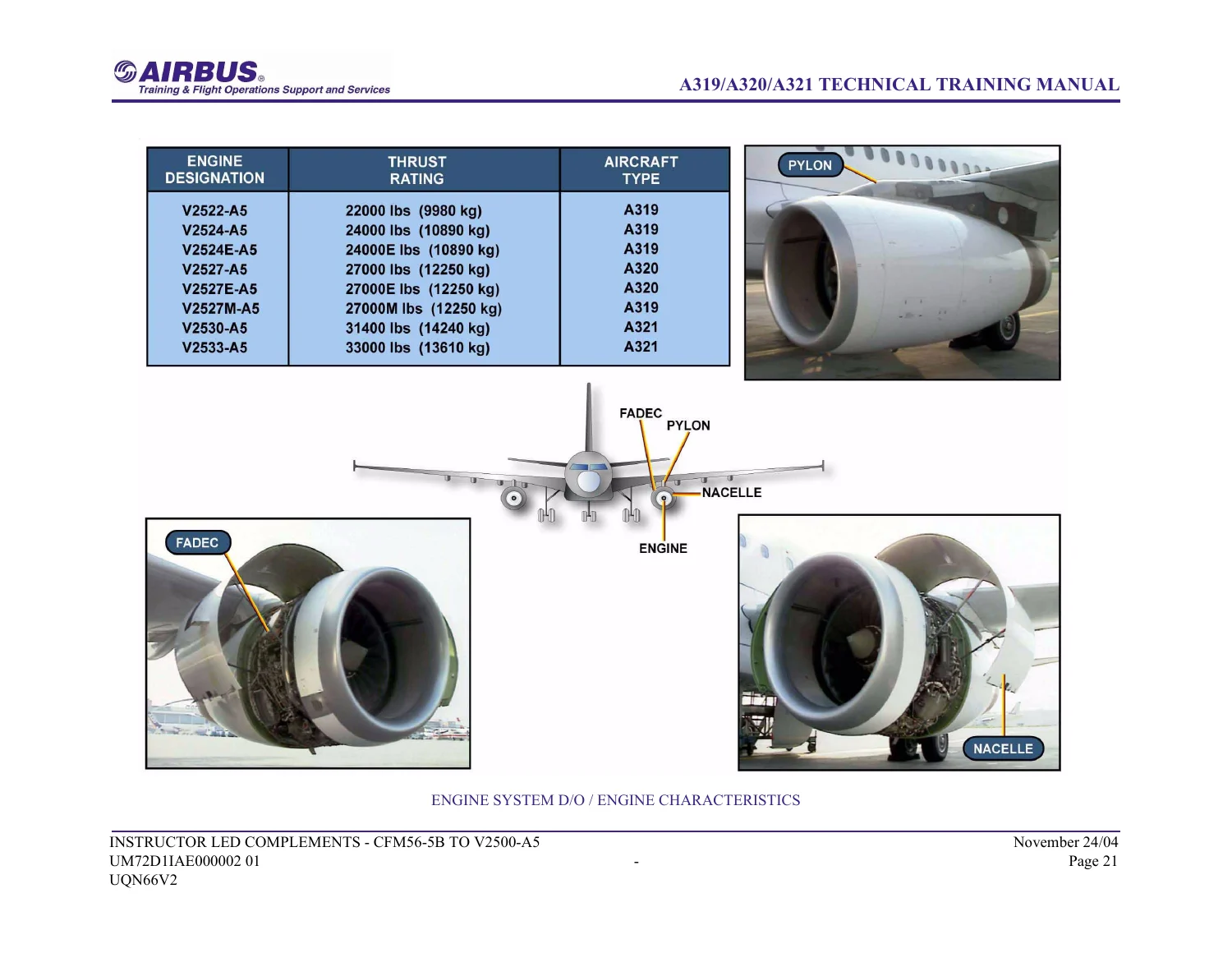
The course follows the V2500-A5 power plant on A319, A320 and A321. Engine ratings shown in the characteristics tables run from the V2522-A5 at 22,000 lb through the V2533-A5 at 33,000 lb, with intermediate marks V2524-A5, V2524E-A5, V2527-A5, V2527E-A5, V2527M-A5 and V2530-A5. Thrust is set by the engine data-programming plug. Later module headers also carry the course path A318/19/20/21 CFM56-5B to A319/20/21 V2500-A5/ME, so the book is aimed at people already familiar with the CFM56-5B installation who need the V2500 differences.
File Details
- Manual type: Technical Training Manual — Instructor Led Complements
- Brand / family: Airbus A319 / A320 / A321
- Engine family: IAE V2500-A5 (course path CFM56-5B to V2500-A5)
- Language: English
- Page count: 607
- File format: PDF
- Document identifier: UQN66V2
- Reference: UQ0064362
- Date printed in the footer: November 24/04 (November 2004)
- Module codes visible: UM71D11AE000002 01, UM72D11AE000002 01, UM79D11AE000002 01, UM70YSIAE000002 01
What the V2500-A5 Power Plant Looks Like in This Course
The opening engine-system block describes two IAE V2500-A5 turbofans hung on wing pylons, enclosed by the nacelle, and controlled by a Full Authority Digital Engine Control (FADEC) that also feeds monitoring and troubleshooting data. Take-off thrust in the general-parameters table is 22,000 / 24,000 lb on A319, 27,000 lb on A320, and 31,400 / 33,000 lb on A321. Flat-rate temperatures are given as 55 °C (A319), 45 °C (A320) and 30 °C (A321). Fan diameter is 63.5 in on all three. Airflow, bypass ratio, climb-pressure ratio, cruise specific fuel consumption (0.543 lb/lb/hr) and power-plant weight (7,500 lb / 3,402 kg) are tabulated beside a photograph of the complete engine on a stand.
Approved fuels listed for training reference include Jet A-1, Jet A, Jet B or JP4, JP5, TS-1, RT and JP8, with the note that Airbus documentation remains the authority for fuel use. Approved oil brands shown on the oil-system schematic include Mobil Jet II, Aeroshell Turbine Oil 500 / 560 / 555, BP turbo oil 2380, Castrol 5000, Mobil Jet 254, BPTO 2197, Turbo Nycoil 600 and Mobil Jet 291. The text tells the student to service only oils listed in AMM chapter 20 and to avoid mixing brands.
Chapters Covered
- Power Plant Installation D/O — air intake cowl; fan cowl doors (LH and RH); thrust reverser “C” ducts; firewalls and acoustic panels; common nozzle assembly and exhaust cone; forward mount and aft mount; fluid disconnect panel; fan electrical connector panel; core electrical junction box
- Engine System D/O — engine characteristics and ratings; general parameters; bearings No.1 through No.5; engine seals; approved fuels; LPC fan, LPC intermediate case and 10-stage HPC; compressor operation, stall and surge; combustion section; borescope ports
- Engine Monitoring D/O — EEC and vibration monitoring on ECAM; primary parameters (EPR, EGT, N1, N2, thrust limit mode, EPR rating limit, fuel flow); secondary parameters (fuel used, oil quantity/pressure/temperature, ignition, start valve, bleed pressure, vibration, filter clog, nacelle temperature); optional P12.5 / P2.5 / T2.5 sensors; HP turbine P3/T3
- Oil System D/O — dry-sump full-flow supply, scavenge and vent circuits; Heat Management System; N°4 bearing scavenge valve; approved oils
- Engine Removal and Installation Overview — safety precautions, circuit-breaker isolation, preservation and de-preservation of the power plant
- 26 Engine Fire Protection
- 28 Storage, Venting and Recirculation (including fuel IDG cooling presentation)
- 30 Engine Air Intake Ice Protection
- 36 Pneumatic System — engine bleed air supply components (HPV, PRV, precooler, BMC interface)
- Maintenance Practices — Miscellaneous — safety zones; opening and closing of engine cowl doors; thrust reverser deactivation and lockout; manual operation of T/R sleeves; maintenance operations
- 71 Power Plant
- 73 Engine Fuel and Control
- 74 Ignition and Starting
- 75 Air
- 76 Engine Controls
- 77 Engine Indicating
- 78 Exhaust
- 79 Oil — oil tank, pressure pump and filter, scavenge pumps and filter, chip detectors, de-oiler, ACOC and sensors, N°4 bearing scavenge valve and pressure transducer
Taken together, those blocks walk a technician through the V2500-A5 nacelle and core as installed on the A320 family: how the inlet, fan cowls and “C” ducts hang on the pylon, how thrust and torque travel through the fail-safe forward and aft mounts, which fluids and harnesses break at the disconnect panels, and how the FADEC, EEC, EIU and ECAM pages present primary and secondary engine data. The later ATA modules then reuse that hardware view for fire loops, fuel storage and IDG cooling, intake anti-ice, bleed air, fuel metering, start and ignition, compressor air systems, cockpit engine controls, indicating, the common nozzle / thrust reverser exhaust path, and line-replaceable oil-system parts.
Nacelle, Mounts and Interface Hardware
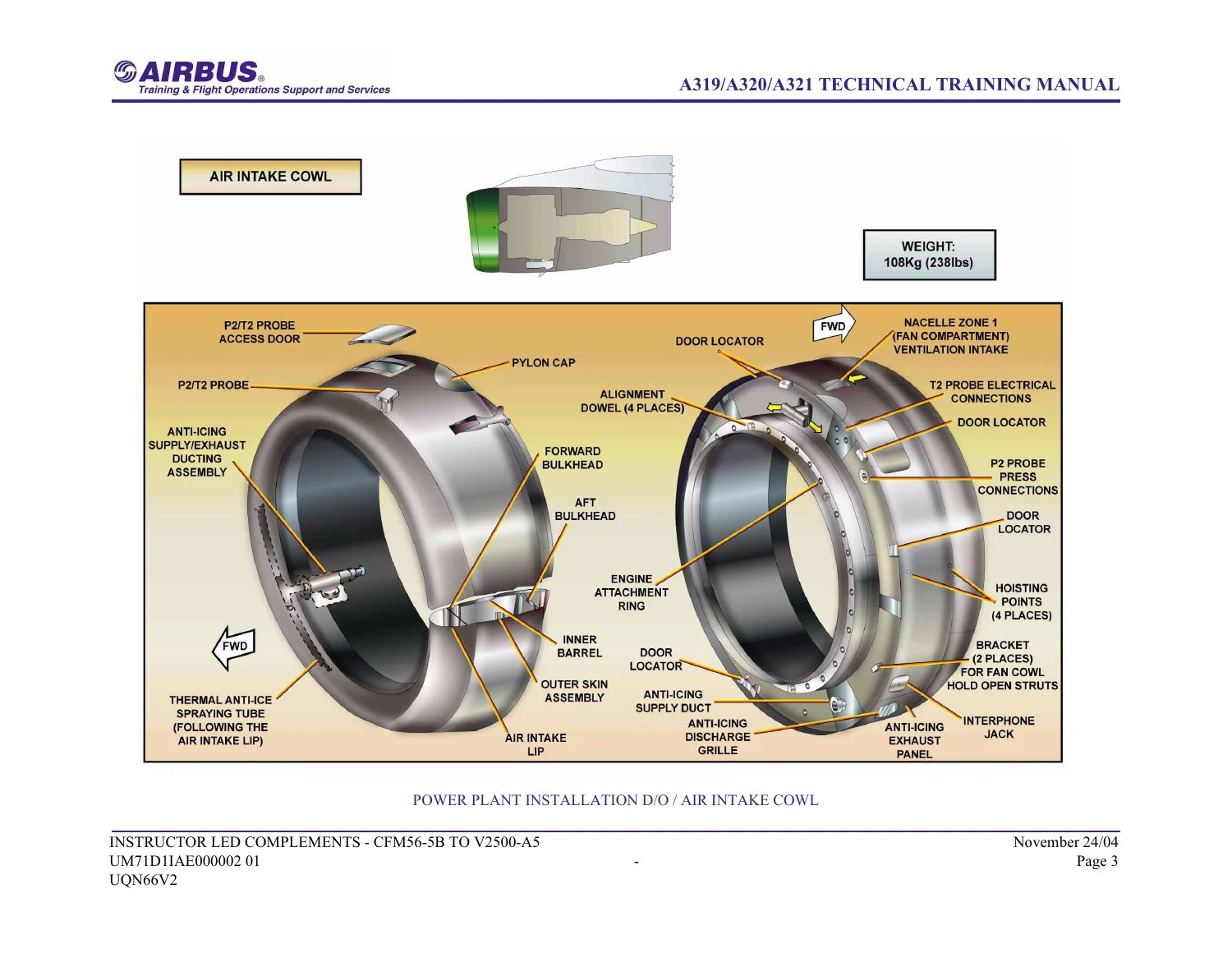
The air intake cowl bolts to the fan-case front flange and carries the anti-ice system, an interphone jack and the P2/T2 probe. Handling provisions printed on the drawing are four hoisting points, 36 identical attach fittings and four alignment dowels. Weight is given as 108 kg (238 lb). Fan cowl doors (LH 36 kg / 79 lb, RH 39 kg / 86 lb) hang on four pylon hinges each and latch on the bottom centerline with four latches; each door has two hoisting points and two hold-open struts, plus access doors for the start valve and oil-tank servicing. Aerodynamic strakes are noted on the A320 inboard nacelle side.
Thrust-reverser “C” ducts are two halves with cascades, blocker doors and translating sleeves. Each half hangs on four pylon hinges, latches with six latches (forward bumper, three center latches behind a hinged panel, aft twin latch), and opens with a hand-pump actuator plus two hold-open rods. Printed weights are 263 kg (580 lb) LH and 260 kg (574 lb) RH. Firewalls and fire seals divide the designated fire zones; the intake-cowl aft bulkhead and inner barrel form a carbon-composite firewall into fan-case zone 1, while acoustic sandwich panels appear in the intake inner barrel, mixed-exhaust structure, Inco 625 honeycomb exhaust cone and translating sleeves.
The Common Nozzle Assembly mixes primary and secondary exhaust, bolts to the turbine-exhaust-case rear flange with 56 bolts, and is listed at 82 kg (181 lb). The exhaust cone (4.5 kg / 10 lb) uses 13 bolts on the inner LP turbine frame. The forward mount, on the intermediate case at the top of the LPC via the engine forward support shaft, carries thrust, vertical and side loads through two thrust-link assemblies, a beam, a cross beam and a support bearing; it is fail-safe and attaches to the pylon with four bolts and self-locking nuts. The aft mount on the turbine-exhaust-case lugs carries torque, vertical and side loads, is free fore and aft for thermal growth, and uses a beam, two side links and a center link with four pylon bolts.
Fluid lines at the left-hand fan-case disconnect panel are fuel supply, fuel return to tank, hydraulic pump suction, pressure delivery and case drain. The right-hand fan electrical connector panel and the core electrical junction box in the forward-mount zone list the harness identities used in the classroom (FADEC power and reset, fire-detection loops, vibration transducers, TLA excitation, IDG harness, anti-ice, start duct and related VC connectors).
Engine Architecture Taught in the Complements
Bearings are presented as a front compartment (No.1 split-inner-race ball bearing for LP axial load, No.2 cylindrical roller, No.3 ball bearing in the internal gearbox) plus No.4 roller in the diffuser/combustor module and No.5 roller on the exhaust case supporting the LPT shaft. Seal coverage includes front-compartment carbon and hydraulic seals, diffuser-case brush and knife-edge seals, stage 1 HPT inner and outer air seals, the stage 2 HPT air seal/spacer, LPT honeycomb seal segments, and No.5 carbon seals.
The compressor is split into the LPC fan module (22-blade rotor and disk), the LPC/intermediate-case module with booster, fan case and internal gearbox, and a ten-stage HPC with variable vanes in the front casing and fixed stators plus bleed manifolds in the rear casing. Operation text explains the split between fan bypass thrust and booster-plus-HPC core flow, LPC bleed for booster surge margin, and stall versus surge. The annular combustor sits in a diffuser case with twenty injector pads, two igniter pads and six borescope bosses. A dedicated borescope-port diagram clocks inspection access from the 3rd stage through the 11th-to-12th stage plus diffuser/burner and 2nd/3rd vane ports.
Monitoring, Oil and Line Practices
Engine monitoring is taught as an EEC-plus-vibration-monitoring loop displayed on ECAM. The EEC takes inlet data from the ADIRUs, commands from the EIU, and sensor inputs from the engine. Primary EWD parameters are EPR, EGT, N1, N2, thrust-limit mode, EPR rating limit and fuel flow. Secondary ENGINE-page items include fuel used, oil quantity, pressure and temperature, ignition, start-valve position, bleed pressure and vibration; filter-clog and nacelle-temperature flags appear when triggered. Fuel used, oil quantity and vibration also show on the CRUISE page.
The oil system is a dry-sump full-flow arrangement with one pressure pump and six gearbox-mounted scavenge pumps. It feeds three bearing compartments plus the angle and main gearboxes. The Heat Management System holds engine oil, IDG oil and fuel temperature inside limits using the FCOC and ACOC. There is no pressure regulator — oil pressure follows N2 — but a cold-start relief valve opens at 450 psi. Scavenge-filter delta-P warns on ECAM above 12 psi and the bypass opens at 20 psi. The N°4 bearing scavenge valve is a two-position pneumatic valve using stage-10 compressor air, open at low speed and restricted at high speed to keep compartment seal delta-P. Anti-syphon features stop tank oil draining into the gearboxes when the engine is static.
IMAGES PREVIEW
Engine-change overview pages list fire-fighting readiness, landing-gear locks and chocks, warning notices on flight controls, landing gear, ENG MASTER levers, FADEC ground power, bleed and the HP ground connector, plus isolation of fire detection and extinguishing, FADEC, ignition, anti-ice, GCU, yellow hydraulic electric pump and hydraulic power. The engine must have been shut down at least five minutes. Preservation guidance splits engines stored up to three months from those stored longer than three months (covers, VPI paper, desiccant, oil-tank fill, wet-motor, and extra VSV / 2.5 bleed lubrication and thrust-reverser corrosion preventive on the longer storage).
Miscellaneous maintenance-practice pages cover safety zones around the power plant, opening and closing of fan cowls and “C” ducts with hold-open rods, thrust-reverser deactivation and lockout, and manual operation of the translating sleeves. Component pages in ATA 79 identify tank, pumps, filters, master chip detector, de-oiler, ACOC, quantity and pressure transmitters, low-pressure switch and the N°4 scavenge valve/transducer by FIN and zone where printed.
Who This Manual Is For
The Airbus A319 A320 A321 V2500-A5 Technical Training Manual CFM56-5B to V2500 Instructor Complements is written for maintenance and training staff who already work CFM56-5B A320-family aircraft and need the V2500-A5 differences: nacelle hardware, mount load paths, FADEC/EEC/ECAM parameter set, oil and heat-management layout, fire, anti-ice, bleed, fuel control, start, indicating and exhaust. Because the source pages forbid using the book as a reference and state that it will not be updated, line work still follows the current AMM, IPC and task cards. The value of this file is structured classroom explanation and labeled drawings that make those official procedures easier to follow.
Get the Training Complements and Start Studying
With this file a technician can study V2500-A5 nacelle removal interfaces, mount architecture, electrical and fluid break points, compressor and combustor layout, borescope access, ECAM primary and secondary parameters, dry-sump oil circuitry, approved fluids, engine-change precautions, cowl and thrust-reverser handling, and the ATA 26 / 28 / 30 / 36 / 71 / 73 / 74 / 75 / 76 / 77 / 78 / 79 modules packed into the 607-page set. Using the procedures and figures as they are printed reduces the chance of mixing CFM56-5B habits with V2500-A5 hardware — different cowl latches, different oil-system valves, different FADEC connector panels and different rating plugs.
After payment the Airbus A319 A320 A321 V2500-A5 Technical Training Manual CFM56-5B to V2500 Instructor Complements is delivered as an instant PDF. There is no shipping wait. Open it on a laptop, tablet or shop computer and print the pages you need for class or review.
Reviews
There are no reviews yet.