★ TRUSTED BY 321,897+ PROFESSIONALS WORLDWIDE
🏒
Trusted Business
Verified & Licensed
πŸ›‘οΈ
Virus Free Files
100% Safe Downloads
πŸ”’
Secure Payment
SSL Protected
⚑
Instant Delivery
Available Immediately
Sale!

Airbus A330 Aircraft Maintenance Manual Chapter 35 Oxygen System – AMM PDF

Original price was: $39.95.Current price is: $23.95.

Complete ATA 35 Oxygen chapter of the Airbus A330 Aircraft Maintenance Manual – crew oxygen, passenger emergency oxygen and portable oxygen systems with removal/installation, test, inspection and troubleshooting procedures. 490-page PDF, Revision 53.

⚑
Instant PDF Download
Available immediately
πŸ’Ύ
Save to Your Device
Download & keep forever
πŸ›‘οΈ
Antivirus Scanned
100% virus-free
🌍
Trusted Worldwide
175,000+ customers

Description

Airbus A330 Aircraft Maintenance Manual Chapter 35 Oxygen System – AMM PDF

The Airbus A330 Aircraft Maintenance Manual Chapter 35 Oxygen System is the complete ATA 35 oxygen chapter of the Airbus A330 AMM, delivered as an instant PDF download. It covers the crew oxygen system, the passenger emergency oxygen system and the portable oxygen system in full, with description and operation, removal and installation, adjustment and test, inspection and check, cleaning and painting, and deactivation/reactivation tasks for every oxygen-related component on the aircraft. Every task carries its own job set-up information, fixtures, tools and support equipment, work zones and access panels, referenced information and step-by-step procedure, exactly as issued in the maintenance manual.

File Details

  • Manual type: Aircraft Maintenance Manual (AMM) – ATA Chapter 35, Oxygen
  • Aircraft: Airbus A330
  • Language: English
  • Page count: 490 pages
  • File format: PDF
  • Revision: Revision nΒ°: 53
  • Issue date: Oct 01/11
  • Effectivity blocks: A/C 001-056, 057-099, 101-149, 151-199, plus the individual effectivity variants shown task by task

Chapters Covered

  • 35-10 Crew Oxygen – Description and Operation, Maintenance Practices, Special Precautions when Working on a Gaseous Oxygen System
  • 35-11 Crew Oxygen Storage – Oxygen Cylinder, Pressure Regulator/Transmitter, Filling Pressure; Cylinder/Valve Assembly Removal and Installation, Hydrostatic Test; Filling Port Removal and Installation
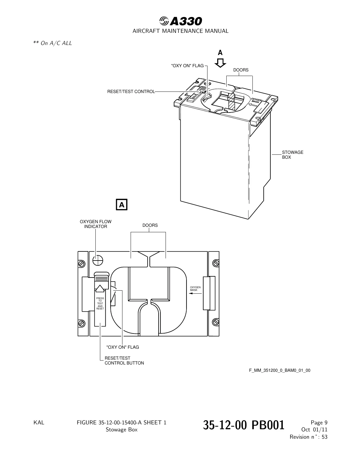
  • 35-12 Oxygen Distribution – Fixed Oxygen Cockpit Installation, Oxygen Distribution Diagram, Stowage Box, Oxygen Mask Assembly, Supply Valve, Radio Connection, Regulator Operation; Full Face/Quick Donning Mask Removal and Installation, Adjustment/Test, Inspection/Check, Cleaning/Painting
  • 35-13 Control and Indicating – Control and Indicating, Overboard Discharge Indicator, ECAM Information; Oxygen Pressure Switch; Pressure Regulator/Transmitter Removal, Installation and Functional Check; Overboard Discharge Indicator Maintenance Practices; LP Oxygen Supply Solenoid Valve
  • 35-20 Passenger Oxygen – Chemical Emergency Oxygen Containers, System Description and Operation
  • 35-21 Passenger Oxygen Storage – Container Location, Adjustment/Test, Inspection/Check; Emergency Oxygen Chemical Container Removal and Installation; Emergency Oxygen Generator Discard and Replacement; Continuous Flow Mask Removal and Installation; Lower Deck Crew Rest Container Removal and Installation
  • 35-23 Oxygen Control and Indicating – Control and Indicating Description/Operation, Deactivation/Reactivation, Adjustment/Test; Altitude Switch Removal and Installation
  • 35-30 Portable Oxygen – Description and Operation, Inspection/Check of Portable Cylinder Pressure and of Protective Breathing Equipment
  • 35-31 Flight Crew Portable Devices – Description and Operation; Breathing Hood Removal, Installation and Inspection/Check
  • 35-32 Cabin Attendants Portable Devices – Description and Operation; Portable Oxygen Cylinder Removal, Installation and Hydrostatic Test; Breathing Hood Removal and Installation

Everything is filed the way the A330 AMM is filed: each system splits into storage, distribution and control and indicating, and every component then gets its own task page with a reason for the job, job set-up, procedure and close-up. That means the Airbus A330 aircraft maintenance manual chapter 35 oxygen PDF can be worked from directly on the aircraft rather than read as a general description of how an oxygen system is built.

The Three Oxygen Systems Covered

The crew oxygen system (35-10 through 35-13) supplies oxygen to four flight crew stations from a high-pressure cylinder mounted in the avionics compartment between frames 4 and 7, feeding full-face quick-donning masks through a pressure regulator/transmitter, an LP solenoid supply valve and a forged distribution manifold. The passenger emergency oxygen system (35-20 through 35-23) uses chemical oxygen generators in overhead, lavatory, galley and door-frame containers, releasing continuous-flow masks automatically when the altitude pressure switch 16WR closes, or manually from the MASK MAN ON pushbutton. The portable oxygen system (35-30 through 35-32) covers the flight crew breathing hood, the cabin attendant protective breathing equipment and the portable high-pressure cylinders with continuous-flow masks.

Procedures, Tests and Inspection Tasks

The test and inspection content is unusually specific for a single ATA chapter. It includes the leakage test of the LP oxygen system for the crew with a nitrogen source, the same test using the oxygen cylinder as source with a temperature-corrected pressure calculation and a 2 psi tolerance, the leakage test using the VARIAN HELITEST tool with a 10 percent helium / 90 percent nitrogen mixture and component-by-component maximum leak values in PPM, the cross check of quantity indications on ECAM, oxygen fill panel and cylinder gauges, the functional check of the automatic mask release, the operational check of the manual mask release, the operational test of each emergency oxygen container circuit, packing of the oxygen mask assemblies into the emergency oxygen containers, and the hydrostatic test of both the fixed and portable oxygen cylinders. Where a step needs a figure – torque, pressure, tolerance or interval – the figure is printed with it.

Safety and Contamination Control

The gaseous oxygen special precautions are repeated at the head of the tasks that need them: hydrocarbon exclusion, aircraft and ground cart grounding, no ignition source inside 15 m of the refill equipment, no maintenance within 5 m of the work area, stopping of refuelling and of all fuel, hydraulic and flammable-material work, lint-free cotton gloves for touching system components, dry clean metal or plastic plugs on anything removed temporarily, sealed vinyl bags for each pipe or unit, and slow opening and hand-tight closing of the cylinder manual shutoff valves.

What This A330 Oxygen AMM Lets You Do

With this chapter open you can remove and install the crew oxygen cylinder and pressure regulator/transmitter, replace the LP oxygen supply solenoid valve, the oxygen pressure switch and the overboard discharge indicator, service and leak-test the low-pressure crew oxygen distribution circuit, remove and install every full-face quick-donning mask and stowage box, service the emergency oxygen containers and their chemical generators, replace continuous-flow passenger masks, carry out the automatic and manual mask release checks and the emergency oxygen container circuit tests, and inspect and discard protective breathing equipment.

Complete PDF Bookmark Tree

Complete Bookmarks

The complete bookmarks in the β€œAirbus A330 Aircraft Maintenance Manual Chapter 35 Oxygen System – AMM PDF” are as follows:

Manual Front Matter
Chapter 05 – TIME LIMITS – MAINTENANCE CHECKS
Chapter 06 – DIMENSIONS AND AREAS
Chapter 07 – LIFTING AND SHORING
Chapter 08 – LEVELING AND WEIGHING
Chapter 09 – TOWING AND TAXIING
Chapter 10 – PARKING, MOORING, STORAGE & RETURN TO SERVICE
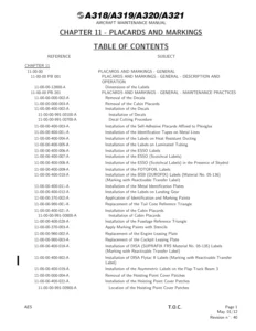
Chapter 11 – PLACARDS AND MARKINGS
Chapter 12 – SERVICING
Chapter 20 – STANDARD PRACTICES – AIRFRAME
Chapter 21 – AIR CONDITIONING
Chapter 22 – AUTO FLIGHT
Chapter 23 – COMMUNICATIONS
Chapter 24 – ELECTRICAL POWER
Chapter 25 – EQUIPMENT/FURNISHINGS
Chapter 26 – FIRE PROTECTION
Chapter 27 – FLIGHT CONTROLS
Chapter 28 – FUEL
Chapter 29 – HYDRAULIC POWER
Chapter 30 – ICE AND RAIN PROTECTION
Chapter 31 – INDICATING/RECORDING SYSTEMS
Chapter 32 – LANDING GEAR
Chapter 33 – LIGHTS
Chapter 34 – NAVIGATION
Chapter 35 – OXYGENp. 1
Table of Contentsp. 1
35-00 – OXYGEN – GENERALp. 10
35-00-00 – OXYGEN – GENERALp. 10
35-00-00 PB 001 CONF 00 – OXYGEN – GENERAL – DESCRIPTION AND OPERATIONp. 10
Generalp. 10
System Descriptionp. 11
35-00-00 PB 201 CONF 00 – OXYGEN – GENERAL – MAINTENANCE PRACTICESp. 12
35-00-00-860-801-A – Special Precautions when Working on a Gaseous Oxygen Systemp. 12
35-10 – CREW OXYGENp. 14
35-10-00 – CREW OXYGENp. 14
35-10-00 PB 001 CONF 00 – CREW OXYGEN – DESCRIPTION AND OPERATIONp. 14
Generalp. 14
System Descriptionp. 15
Operation/Control and Indicatingp. 16
Figure 35-10-00-11950-C – Fwd Cockpit Installationp. 17
Figure 35-10-00-12000-A – Aft Cockpit Installationp. 18
Figure 35-10-00-12050-A – Avionics Cockpit Installationp. 19
Figure 35-10-00-13600-E – Oxygen-General Descriptionp. 20
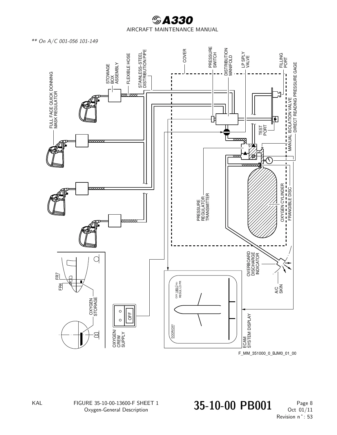
Figure 35-10-00-13600-F – Oxygen-General Descriptionp. 21
Figure 35-10-00-15000-C – Electrical Diagramp. 22
35-10-00 PB 401 CONF 00 – CREW OXYGEN – DEACTIVATION/REACTIVATIONp. 23
35-10-00-040-803-A – Check of High Pressure of the Crew Oxygen Cylinderp. 23
35-10-00 PB 501 CONF 00 – CREW OXYGEN – ADJUSTMENT/TESTp. 25
35-10-00-790-801-A – Leakage Test of the LP Oxygen System for the Crewp. 25
Figure 35-10-00-991-01000-A – Preparation for the Testp. 29
Figure 35-10-00-991-01200-A – Test Installationp. 30
35-10-00-790-801-A-01 – Leakage Test of the LP Oxygen System for the Crew with the Oxygen Cylinder Sourcep. 31
Figure 35-10-00-991-01100-A – Preparation for the testp. 35
35-10-00-790-802-A – Leakage Test of the LP Oxygen System for the Crew with the VARIAN HELITEST TOOLp. 36
35-10-00 PB 601 CONF 00 – CREW OXYGEN – INSPECTION/CHECKp. 40
35-10-00-200-803-A – Inspection of the Oxygen Pressure for the Flight Crewp. 40
Figure 35-10-00-991-00300-C – Minimum Flight Crew Oxygen Pressurep. 42
Figure 35-10-00-991-00300-E – Minimum Flight Crew Oxygen Pressurep. 43
35-10-00-200-806-A – Cross Check of Quantity Indications on ECAM, Oxygen Fill Panel and Gauges on Oxygen Cylindersp. 44
Figure 35-10-00-991-01300-A – Pressure Indicationp. 46
35-11 – CREW OXYGEN STORAGEp. 47
35-11-00 – CREW OXYGEN STORAGEp. 47
35-11-00 PB 001 CONF 00 – CREW OXYGEN STORAGE – DESCRIPTION AND OPERATIONp. 47
Generalp. 47
Component Locationp. 49
Component Descriptionp. 50
Figure 35-11-00-11700-A – Oxygen Cylinderp. 52
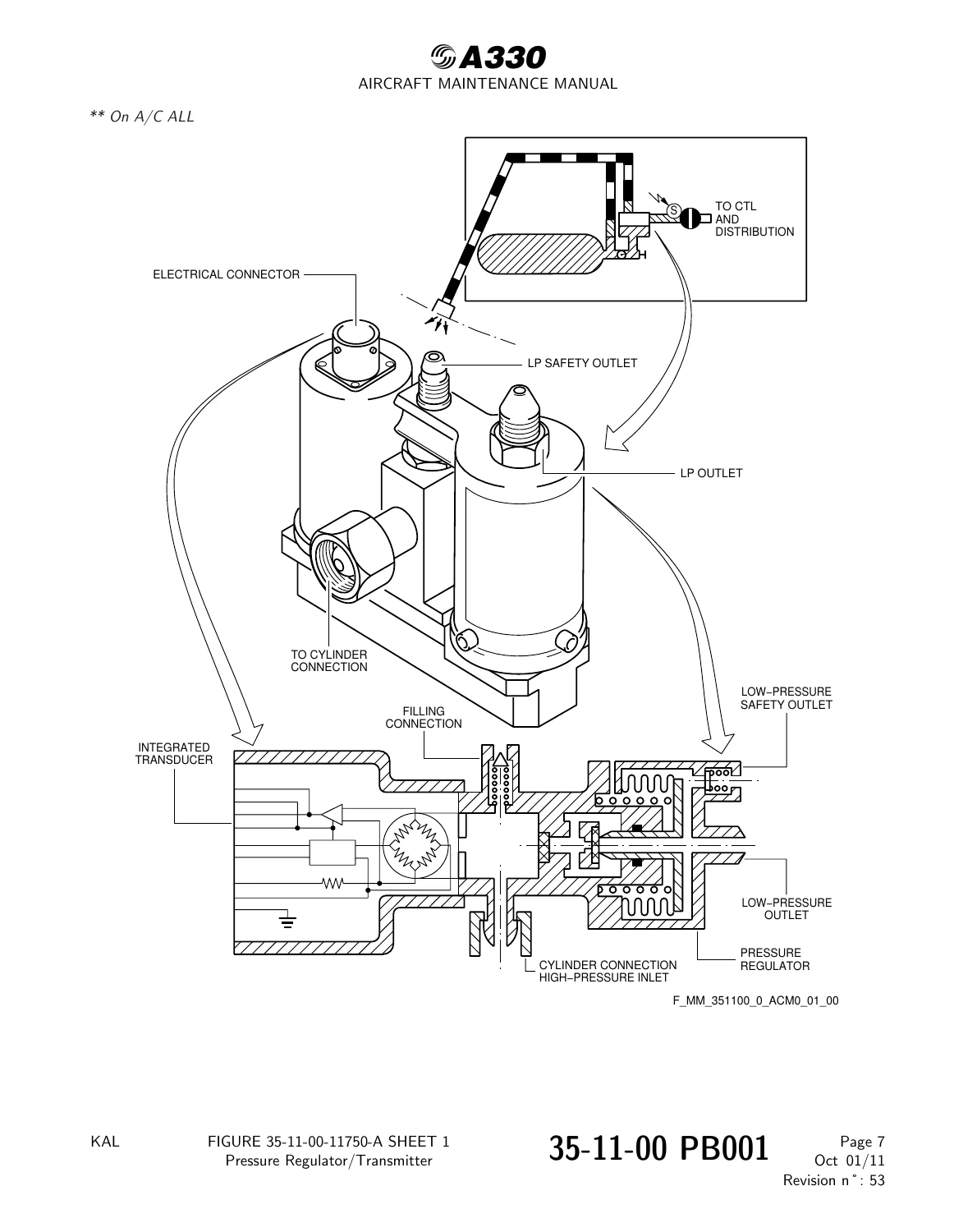
Figure 35-11-00-11750-A – Pressure Regulator/Transmitterp. 53
Figure 35-11-00-11800-A – Filling Pressurep. 54
Figure 35-11-00-13000-A – Oxygen Storagep. 55
Figure 35-11-00-13000-B – Oxygen Storagep. 56
35-11-41 – CYLINDER / VALVE ASSY – OXYGENp. 57
35-11-41 PB 401 CONF 00 – CYLINDER / VALVE ASSY – OXYGEN – REMOVAL/INSTALLATIONp. 57
35-11-41-000-801-A – Removal of the Oxygen Cylinder/Valve Assyp. 57
Figure 35-11-41-991-00100-B – Oxygen Storage Cylinder (5750HT)p. 60
Figure 35-11-41-991-00100-A – Oxygen Storage Cylinder (5750HT)p. 61
35-11-41-400-801-A – Installation of the Oxygen Cylinder/Valve Assyp. 62
35-11-41 PB 601 CONF 00 – CYLINDER / VALVE ASSY – OXYGEN – INSPECTION/CHECKp. 65
35-11-41-750-801-A – Hydrostatic Test of the Oxygen Cylinder Assembly(ies)p. 65
35-11-42 – FILLING PORT – OXYGENp. 66
35-11-42 PB 401 CONF 00 – FILLING PORT – OXYGEN – REMOVAL/INSTALLATIONp. 66
35-11-42-000-801-A – Removal of the Oxygen Filling Portp. 66
Figure 35-11-42-991-00100-A – Oxygen Filling Portp. 68
35-11-42-400-801-A – Installation of the Oxygen Filling Portp. 69
35-12 – OXYGEN DISTRIBUTIONp. 71
35-12-00 – OXYGEN DISTRIBUTIONp. 71
35-12-00 PB 001 CONF 00 – OXYGEN DISTRIBUTION – DESCRIPTION AND OPERATIONp. 71
Generalp. 71
Component Locationp. 72
System Descriptionp. 73
Component Descriptionp. 74
Operation/Control and Indicatingp. 76
Figure 35-12-00-12250-A – Fixed Oxygen-Cockpit Installationp. 77
Figure 35-12-00-12400-A – Oxygen Distribution-Diagramp. 78
Figure 35-12-00-15400-A – Stowage Boxp. 79
Figure 35-12-00-15450-A – Oxygen Mask Assemblyp. 80
Figure 35-12-00-15500-A – Supply Valve-Stowage Boxp. 81
Figure 35-12-00-15500-B – Supply Valve – Stowage Boxp. 82
Figure 35-12-00-15550-A – Radio Connection.p. 83
Figure 35-12-00-15600-A – Oxygen box with oxygen mask.p. 84
Figure 35-12-00-17150-A – Regulator- Oxygen Mask Assembly (principle)p. 85
Figure 35-12-00-17200-A – Operation of the Maskp. 86
Figure 35-12-00-17250-A – Regulator-Oxygen Mask assemblyp. 87
Figure 35-12-00-17250-B – Regulator-Oxygen Mask Assemblyp. 88
35-12-41 – MASK – FULL FACE/QUICK DONNING, OXYGENp. 89
35-12-41 PB 401 CONF 00 – MASK – FULL FACE/QUICK DONNING, OXYGEN – REMOVAL/INSTALLATIONp. 89
35-12-41-000-801-A – Removal of the Oxygen-Mask Stowage boxp. 89
Figure 35-12-41-991-00100-A – Oxygen-Mask Stowage-Boxp. 92
35-12-41-400-801-A – Installation of the Oxygen-Mask Stowage Boxp. 93
35-12-41-000-802-A – Removal of the Full-Face/Quick-Donning Oxygen Maskp. 96
Figure 35-12-41-991-00200-A – Full-Face/Quick-Donning Oxygen-Maskp. 98
35-12-41-400-802-A – Installation of the Full-Face/Quick-Donning Oxygen Maskp. 99
Figure 35-12-41-991-00900-A – Full-Face/Quick-Donning Oxygen-Mask – Stowage Boxp. 102
35-12-41 PB 501 CONF 00 – MASK – FULL FACE/QUICK DONNING, OXYGEN – ADJUSTMENT/TESTp. 103
35-12-41-710-801-A – Operational Test of the Full-Face/Quick-Donning Oxygen Maskp. 103
35-12-41-720-801-A – Functional Test of Oxygen-Mask Regulatorp. 106
35-12-41 PB 601 CONF 00 – MASK – FULL FACE/QUICK DONNING, OXYGEN – INSPECTION/CHECKp. 107
35-12-41-200-803-A – Visual Check of Oxygen Masks (Out of Box with Inflated Harness)p. 107
Figure 35-12-41-991-00500-A – Adjustment of Oxygen Mask Strap Separatorp. 110
35-12-41-200-804-A – Check of the Correct Position of the Mask Lock, and Correct Torque of the Retaining Screwp. 111
Figure 35-12-41-991-00600-A – Mask Lock and Retaining Screwp. 114
35-12-41 PB 701 CONF 00 – MASK – FULL FACE/QUICK DONNING, OXYGEN – CLEANING/PAINTINGp. 115
35-12-41-100-802-A – Cleaning of Oxygen Masksp. 115
35-13 – CONTROL AND INDICATINGp. 117
35-13-00 – CONTROL AND INDICATINGp. 117
35-13-00 PB 001 CONF 00 – CONTROL AND INDICATING – DESCRIPTION AND OPERATIONp. 117
Generalp. 117
Component Locationp. 118
System Descriptionp. 119
Component Descriptionp. 120
Operation/Control and Indicatingp. 121
Figure 35-13-00-13950-C – Control and Indicatingp. 123
Figure 35-13-00-14000-A – Overboard discharge Indicatorp. 124
Figure 35-13-00-16700-A – ECAM Informationp. 125
35-13-14 – PRESSURE SWITCH – OXYGENp. 126
35-13-14 PB 401 CONF 00 – PRESSURE SWITCH – OXYGEN – REMOVAL/INSTALLATIONp. 126
35-13-14-000-801-A – Removal of the Oxygen Pressure Switchp. 126
Figure 35-13-14-991-00100-D – Oxygen Pressure Switch (6WV)p. 129
Figure 35-13-14-991-00100-A – Oxygen Pressure Switch (6WV)p. 130
35-13-14-400-801-A – Installation of the Oxygen Pressure Switchp. 131
35-13-15 – PRESSURE REGULATOR / TRANSMITTER – OXYGENp. 134
35-13-15 PB 401 CONF 00 – PRESSURE REGULATOR / TRANSMITTER – OXYGEN – REMOVAL/INSTALLATIONp. 134
35-13-15-000-801-A – Removal of the Oxygen Pressure Regulator/Transmitterp. 134
Figure 35-13-15-991-00100-D – Oxygen Pressure Regulator/Transmitterp. 137
Figure 35-13-15-991-00100-A – Oxygen Pressure Regulator/Transmitterp. 138
35-13-15-400-801-A – Installation of the Oxygen Pressure Regulator/Transmitterp. 139
35-13-15-920-801-A – Remove Pressure Reducer Transmitter for Functional Check (in workshop)p. 143
35-13-22 – INDICATOR – OVERBOARD DISCHARGEp. 144
35-13-22 PB 201 CONF 00 – INDICATOR – OVERBOARD DISCHARGE – MAINTENANCE PRACTICESp. 144
35-13-22-600-801-A – Replacement of the Overboard Discharge Indicatorp. 144
Figure 35-13-22-991-00100-D – Overboard Discharge Indicatorp. 148
Figure 35-13-22-991-00100-A – Overboard Discharge Indicatorp. 149
Figure 35-13-22-991-00200-A – Location of the Overboard Discharge Indicatorp. 150
35-13-51 – VALVE – SOLENOID, LP OXYGEN SUPPLYp. 151
35-13-51 PB 401 CONF 00 – VALVE – SOLENOID, LP OXYGEN SUPPLY – REMOVAL/INSTALLATIONp. 151
35-13-51-000-801-A – Removal of the LP Oxygen-Supply Solenoid-Valvep. 151
Figure 35-13-51-991-00100-D – LP Oxygen-Supply Solenoid-Valve 2HTp. 154
Figure 35-13-51-991-00100-A – LP Oxygen-Supply Solenoid-Valve 2HTp. 155
35-13-51-400-802-A – Installation of the LP Oxygen-Supply Solenoid-Valvep. 156
35-20 – PASSENGER OXYGENp. 160
35-20-00 – PASSENGER OXYGENp. 160
35-20-00 PB 001 CONF 00 – PASSENGER OXYGEN – DESCRIPTION AND OPERATIONp. 160
Generalp. 160
Component Locationp. 161
System Descriptionp. 162
Power Supplyp. 163
Operation/Control and Indicatingp. 164
Figure 35-20-00-12150-AQ – Chemical Emergency Oxygen-Containersp. 165
Figure 35-20-00-12150-BJ – Chemical Emergency Oxygen-Containersp. 166
Figure 35-20-00-12150-BK – Chemical Emergency Oxygen-Containersp. 167
Figure 35-20-00-12150-DF – CHEMICAL EMERGENCY OXYGEN-CONTAINERp. 168
Figure 35-20-00-12150-HQ – Chemical Emergency Oxygen-Containersp. 169
Figure 35-20-00-12150-HW – Chemical Emergency Oxygen-Containersp. 170
Figure 35-20-00-12150-ID – Chemical Emergency Oxygen-Containersp. 171
Figure 35-20-00-12150-KA – Chemical Emergency Oxygen-Containersp. 172
35-21 – PASSENGER OXYGEN STORAGEp. 173
35-21-00 – PASSENGER OXYGEN STORAGEp. 173
35-21-00 PB 001 CONF 00 – PASSENGER OXYGEN STORAGE – DESCRIPTION AND OPERATIONp. 173
Generalp. 173
Component Locationp. 174
System Descriptionp. 176
Power Supplyp. 177
Component Descriptionp. 178
Operation/Control and Indicatingp. 180
Tesp. 181
Figure 35-21-00-12150-AQ – Chemical Emergency Oxygen-Container – Locationp. 182
Figure 35-21-00-12150-BK – Chemical Emergency Oxygen-Container – Locationp. 183
Figure 35-21-00-12150-BL – Chemical Emergency Oxygen-Container – Locationp. 184
Figure 35-21-00-12150-DA – Chemical Emergency Oxygen-Container – Locationp. 185
Figure 35-21-00-12150-H0 – Chemical Emergency Oxygen-Container – Locationp. 186
Figure 35-21-00-12150-HF – Chemical Emergency Oxygen-Container – Locationp. 187
Figure 35-21-00-12150-HM – Chemical Emergency Oxygen-Container – Locationp. 188
Figure 35-21-00-12150-JQ – Chemical Emergency Oxygen-Container – Locationp. 189
Figure 35-21-00-12200-A – Chemical Emergency Oxygen-Container – Shown with the Door Open (Example)p. 190
Figure 35-21-00-12200-D – Chemical Emergency Oxygen-Container – Shown with the Door Open (Example)p. 191
Figure 35-21-00-12250-B – Chemical Emergency Oxygen-Container – Operated (Example)p. 192
Figure 35-21-00-12250-D – Chemical Emergency Oxygen-Container – Operated (Example)p. 193
Figure 35-21-00-12250-G – Oxygen Container (Operated)p. 194
Figure 35-21-00-13500-A – Manual Operationp. 199
Figure 35-21-00-13500-C – Manual Operationp. 200
Figure 35-21-00-16300-A – Chemical Oxygen Generatorp. 201
Figure 35-21-00-17450-C – Cabin Pressure Altitude/Descent Profilep. 202
Figure 35-21-00-17500-A – Passenger Oxygen System – Electrical Schematicp. 203
Figure 35-21-00-17500-F – Passenger Oxygen System – Electrical Schematicp. 205
35-21-00 PB 501 CONF 00 – PASSENGER OXYGEN STORAGE – ADJUSTMENT/TESTp. 208
35-21-00-720-801-A – Functional Check of the Automatic Mask Releasep. 208
Figure 35-21-00-991-00400-A – Emergency Oxygen Control and Indicatingp. 222
35-21-00-710-804-A – Operational Check of the Manual Mask Releasep. 223
35-21-00-710-805-A – Operational Test of a Circuit of the Emergency Oxygen Containersp. 226
Figure 35-21-00-991-00600-E0 – Power Supplyp. 246
Figure 35-21-00-991-00600-DZ – Power Supplyp. 247
Figure 35-21-00-991-00600-DP – Power Supplyp. 248
Figure 35-21-00-991-00600-EI – Power Supplyp. 249
Figure 35-21-00-991-00600-AE – Power Supplyp. 250
Figure 35-21-00-991-00500-AD – Emergency Oxygen-Container Circuitp. 251
Figure 35-21-00-991-00500-DL – Emergency Oxygen-Container Circuitp. 255
Figure 35-21-00-991-00500-DW – Emergency Oxygen-Container Circuitp. 259
Figure 35-21-00-991-00500-DV – Emergency Oxygen-Container Circuitp. 263
Figure 35-21-00-991-00500-EE – Emergency Oxygen-Container Circuitp. 267
35-21-00-710-806-A – Operational Test of the LD-MCR Circuitp. 271
35-21-00 PB 601 CONF 00 – PASSENGER OXYGEN STORAGE – INSPECTION/CHECKp. 273
35-21-00-210-802-A – Visual Check of Chemical Oxygen Generator for Signs of Dischargep. 273
Figure 35-21-00-991-00100-C – Emergency Oxygen Container (Chemical)p. 276
Figure 35-21-00-991-00100-D – Emergency Oxygen Container (Chemical)p. 277
Figure 35-21-00-991-00100-A – Emergency Oxygen Container (Chemical)p. 278
35-21-00-210-803-A – Detailed Inspection of Oxygen Masksp. 281
35-21-00-210-804-A – Visual Check of CRR Chemical Oxygen Generator for Signsp. 284
35-21-41 – CONTAINER – EMERGENCY OXYGEN, CHEMICALp. 286
35-21-41 PB 401 CONF 00 – CONTAINER – EMERGENCY OXYGEN, CHEMICAL – REMOVAL/INSTALLATIONp. 286
35-21-41-000-801-A – Removal of the Emergency Oxygen Containersp. 286
Figure 35-21-41-991-00100-GS – Emergency Oxygen-Container Layoutp. 295
Figure 35-21-41-991-00100-GX – Emergency Oxygen-Container Layoutp. 296
Figure 35-21-41-991-00100-HD – Emergency Oxygen-Container Layoutp. 297
Figure 35-21-41-991-00100-S – Emergency Oxygen-Container Layoutp. 298
Figure 35-21-41-991-00100-AY – Emergency Oxygen-Container Layoutp. 299
Figure 35-21-41-991-00100-AZ – Emergency Oxygen-Container Layoutp. 300
Figure 35-21-41-991-00100-CN – EMERGENCY OXYGEN-CONTAINER LAYOUTp. 301
Figure 35-21-41-991-00100-IR – Emergency Oxygen-Container Layoutp. 302
Figure 35-21-41-991-00600-A – Emergency Oxygen Containerp. 303
Figure 35-21-41-991-00500-B – Emergency Oxygen Container in the Passenger Service Channelp. 304
Figure 35-21-41-991-00700-A – Emergency Oxygen Containerp. 306
Figure 35-21-41-991-00800-A – Emergency Oxygen Containerp. 307
Figure 35-21-41-991-00900-A – Emergency Oxygen Containerp. 308
Figure 35-21-41-991-00400-A – Emergency Oxygen Container in Lavatory Ap. 309
Figure 35-21-41-991-01100-A – Emergency Oxygen Containerp. 310
35-21-41-400-801-A – Installation of the Emergency Oxygen Containersp. 311
Figure 35-21-41-991-01400-A – Emergency Oxygene Container – Remval of the Safety Ringp. 324
Figure 35-21-41-991-01500-A – Installation Position of the Emergency Oxygen Containerp. 325
35-21-42 – GENERATOR – EMERGENCY OXYGENp. 326
35-21-42 PB 401 CONF 00 – GENERATOR – EMERGENCY OXYGEN – REMOVAL/INSTALLATIONp. 326
35-21-42-920-801-A – Discard Chemical Oxygen Generatorsp. 326
Figure 35-21-42-991-00100-C – Emergency Oxygen Generator, Type 1 Container (Example)p. 332
Figure 35-21-42-991-00200-A – Emergency Oxygen Generator, Type 2 and Type 3 Container (Example)p. 333
Figure 35-21-42-991-01000-A – Emergency Oxygen Generator, Type 5 Container (Example)p. 334
Figure 35-21-42-991-01100-A – Emergency Oxygen Generator, Type 6 Container (Example)p. 335
35-21-42-920-802-A – Discard CRR Chemical Oxygen Generatorsp. 336
Figure 35-21-42-991-00700-A – Emergency Oxygen Generator, Type 2 Container (CRC)p. 339
35-21-42-960-801-A – Replacement of the Emergency Oxygen Generator after usep. 340
Figure 35-21-42-991-00800-A – Emergency Oxygen Generatorp. 348
Figure 35-21-42-991-00800-D – Emergency Oxygen Generatorp. 349
Figure 35-21-42-991-00900-A – Emergency Oxygen Generator, Type 2 and Type 3 Container (Example)p. 350
Figure 35-21-42-991-01200-A – Emergency Oxygen Generator, Type 5 Container (Example)p. 351
Figure 35-21-42-991-01300-A – Emergency Oxygen Generator, Type 6 Container (Example)p. 352
35-21-43 – MASK – CONTINUOUS FLOWp. 353
35-21-43 PB 401 CONF 00 – MASK – CONTINUOUS FLOW – REMOVAL/INSTALLATIONp. 353
35-21-43-000-801-A – Removal of the Oxygen Masksp. 353
Figure 35-21-43-991-00100-A – Oxygen Mask Assembliesp. 355
35-21-43-400-801-A – Installation of the Oxygen Masksp. 356
35-21-44 – CONTAINER – EMERGENCY OXYGEN, CHEMICAL ((CREW REST))p. 358
35-21-44 PB 401 CONF 00 – CONTAINER – EMERGENCY OXYGEN, CHEMICAL ((CREW REST)) – REMOVAL/INSTALLATIONp. 358
35-21-44-000-801-A – Removal of the Emergency Oxygen (Chemical) Container of the Lower Deck Crew Restp. 358
Figure 35-21-44-991-00100-E – Container Emergency Oxygen – Chemical – LD-MCRp. 361
Figure 35-21-44-991-00100-P – Container Emergency Oxygen – Chemical – LD-MCRp. 362
Figure 35-21-44-991-00400-A – Removal of the Safety Ring from the Emergency Oxygen (Chemical) Containerp. 363
35-21-44-400-801-A – Installation of the Emergency Oxygen (Chemical) Container of the Lower Deck Crew Restp. 364
35-23 – OXYGEN CONTROL AND INDICATINGp. 368
35-23-00 – OXYGEN CONTROL AND INDICATINGp. 368
35-23-00 PB 001 CONF 00 – OXYGEN CONTROL AND INDICATING – DESCRIPTION AND OPERATIONp. 368
Generalp. 368
Component Locationp. 369
System Descriptionp. 370
Power Supplyp. 371
Component Descriptionp. 372
Operation/Control and Indicatingp. 373
Tesp. 374
Figure 35-23-00-12250-A – Passenger Oxygen System – Controls and Indicationsp. 375
Figure 35-23-00-14400-A – Passenger Oxygen System – Electrical Schematicp. 376
Figure 35-23-00-14400-F – Passenger Oxygen System – Electrical Schematicp. 378
35-23-00 PB 401 CONF 00 – OXYGEN CONTROL AND INDICATING – DEACTIVATION/REACTIVATIONp. 381
35-23-00-040-801-A – Check of the AUTO Control function of the MASK MAN pushbuttonp. 381
Figure 35-23-00-991-01900-A – Emergency Oxygen Control and Indicatingp. 389
35-23-00 PB 501 CONF 00 – OXYGEN CONTROL AND INDICATING – ADJUSTMENT/TESTp. 390
35-23-00-550-801-A – Packing of the Oxygen Mask Assemblies in the Emergency-Oxygen Containersp. 390
Figure 35-23-00-991-00300-B – Packing of the Oxygen Masks – Examplep. 392
Figure 35-23-00-991-00300-D – Packing of the Oxygen Masks – Examplep. 394
Figure 35-23-00-991-00300-A – Packing of the Oxygen Masks – Examplep. 396
35-23-00-710-808-A – Operational Check of In-Seat Power Supply Interruptionp. 398
35-23-15 – SWITCH – ALTITUDEp. 401
35-23-15 PB 401 CONF 00 – SWITCH – ALTITUDE – REMOVAL/INSTALLATIONp. 401
35-23-15-000-801-A – Removal of the Altitude Switchp. 401
Figure 35-23-15-991-00100-A – Altitude Switchp. 403
35-23-15-400-801-A – Installation of the Altitude Switchp. 404
35-30 – PORTABLE OXYGENp. 406
35-30-00 – PORTABLE OXYGENp. 406
35-30-00 PB 001 CONF 00 – PORTABLE OXYGEN – DESCRIPTION AND OPERATIONp. 406
Generalp. 406
Component Locationp. 407
System Descriptionp. 408
35-30-00 PB 601 CONF 00 – PORTABLE OXYGEN – INSPECTION/CHECKp. 409
35-30-00-210-801-A – Check of the Pressure of the Portable Oxygen Cylinder with the Gaugep. 409
Figure 35-30-00-991-00100-E0 – Portable Oxygen Equipmentp. 413
Figure 35-30-00-991-00100-EA – Portable Oxygen Equipmentp. 414
Figure 35-30-00-991-00100-EB – Portable Oxygen Equipmentp. 415
Figure 35-30-00-991-00100-GZ – Portable Oxygen Equipmentp. 416
Figure 35-30-00-991-00100-AL – Portable Oxygen Equipmentp. 417
Figure 35-30-00-991-00100-BF – Portable Oxygen Equipmentp. 418
Figure 35-30-00-991-00100-CQ – PORTABLE OXYGEN EQUIPMENTp. 419
Figure 35-30-00-991-00100-DN – PORTABLE OXYGEN EQUIPMENTp. 420
Figure 35-30-00-991-00100-IM – Portable Oxygen Equipmentp. 421
Figure 35-30-00-991-00200-A – Portable Oxygen Cylinderp. 422
Figure 35-30-00-991-00200-D – Portable Oxygen Cylinderp. 423
35-30-00-210-802-A – Check of the Tamper Seal/Serviceability Indication of the Protective Breathing Equipmentp. 424
Figure 35-30-00-991-00300-D – Protective Breathing-Hood Containerp. 427
35-30-00-210-803-A – Detailed Visual Inspection of the Portable Oxygen Cylinder Attachmentp. 428
Figure 35-30-00-991-00400-B – Portable Oxygen-Cylinder Attachmentp. 430
Figure 35-30-00-991-00400-A – Portable Oxygen-Cylinder Attachmentp. 431
35-30-00-210-811-A – Detailed Visual Inspection of the Continuous Flow Maskp. 432
35-31 – FLIGHT CREW PORTABLE DEVICESp. 434
35-31-00 – FLIGHT CREW PORTABLE DEVICESp. 434
35-31-00 PB 001 CONF 04 – FLIGHT CREW PORTABLE DEVICES – DESCRIPTION AND OPERATIONp. 434
Generalp. 434
Component Locationp. 435
General Descriptionp. 436
Component Descriptionp. 437
Operation/Control and Indicatingp. 438
Figure 35-31-00-12250-A – Component Locationp. 439
Figure 35-31-00-16850-A – Operationp. 440
35-31-52 – HOOD – BREATHINGp. 441
35-31-52 PB 401 CONF 00 – HOOD – BREATHING – REMOVAL/INSTALLATIONp. 441
35-31-52-000-802-A – Removal of the Protective Breathing Equipmentp. 441
Figure 35-31-52-991-00100-E – Protective Breathing Equipmentp. 442
35-31-52-400-802-A – Installation of the Protective Breathing Equipmentp. 443
35-31-52-920-801-A – Discard Flight Crew Portable Protective Breathing Equipmentp. 444
Figure 35-31-52-991-00200-B – Protective Breathing Equipmentp. 445
35-31-52 PB 601 CONF 04 – HOOD – BREATHING – INSPECTION/CHECKp. 446
35-31-52-210-802-E – Visual Check of the Tamper Seal/Serviceability Indication of the Protective Breathing Equipmentp. 446
Figure 35-31-52-991-00700-A – Protective Breathing Equipmentp. 448
35-32 – CABIN ATTENDANTS PORTABLE DEVICESp. 449
35-32-00 – CABIN ATTENDANTS PORTABLE DEVICESp. 449
35-32-00 PB 001 CONF 00 – CABIN ATTENDANTS PORTABLE DEVICES – DESCRIPTION AND OPERATIONp. 449
Generalp. 449
Component Locationp. 450
System Descriptionp. 451
Component Descriptionp. 452
Operation/Control and Indicatingp. 454
Figure 35-32-00-12150-AK – Portable Oxygen – Component Locationp. 455
Figure 35-32-00-12150-BE – Portable Oxygen – Component Locationp. 456
Figure 35-32-00-12150-BG – Portable Oxygen – Component Locationp. 457
Figure 35-32-00-12150-CU – PORTABLE OXYGEN – COMPONENT LOCATIONp. 458
Figure 35-32-00-12150-DQ – PORTABLE OXYGEN – COMPONENT LOCATIONp. 459
Figure 35-32-00-12150-EC – PORTABLE OXYGEN – COMPONENT LOCATIONp. 460
Figure 35-32-00-12150-ED – Portable Oxygen – Component Locationp. 461
Figure 35-32-00-12150-EE – Portable Oxygen – Component Locationp. 462
Figure 35-32-00-12150-HE – Cabin Attendants Portable Devicesp. 463
Figure 35-32-00-12150-JQ – Portable Oxygen – Component Locationp. 464
Figure 35-32-00-13700-D – Protective Breathing Equipmentp. 465
Figure 35-32-00-13750-A – Continuous-Flow Mask and Portable Oxygen Cylinder (Example)p. 466
Figure 35-32-00-13750-B – Continuous-Flow Mask and Portable Oxygen Cylinder (Example)p. 467
35-32-42 – CYLINDER – PORTABLE OXYGENp. 468
35-32-42 PB 401 CONF 00 – CYLINDER – PORTABLE OXYGEN – REMOVAL/INSTALLATIONp. 468
35-32-42-000-802-A – Removal of the Portable Oxygen Equipmentp. 468
Figure 35-32-42-991-00400-B – Portable Oxygen Equipmentp. 470
35-32-42-400-801-A – Installation of the Portable Oxygen Equipmentp. 471
35-32-42 PB 501 CONF 00 – CYLINDER – PORTABLE OXYGEN – ADJUSTMENT/TESTp. 473
35-32-42-780-801-A – Remove Oxygen Cylinder for Hydrostatic Testp. 473
Figure 35-32-42-991-00100-DL – Oxygen Cylinder Locationp. 476
Figure 35-32-42-991-00100-DM – Oxygen Cylinders – Locationp. 477
Figure 35-32-42-991-00100-DN – Oxygen Cylinders Locationp. 478
Figure 35-32-42-991-00100-GD – Oxygen Cylinder Locationp. 479
Figure 35-32-42-991-00100-L – Oxygen Cylinder Locationp. 480
Figure 35-32-42-991-00100-AM – Oxygen Cylinder Locationp. 481
Figure 35-32-42-991-00100-AQ – Oxygen Cylinder Locationp. 482
Figure 35-32-42-991-00100-CA – Oxygen Cylinder Locationp. 483
Figure 35-32-42-991-00100-CY – Oxygen Cylinder Locationp. 484
Figure 35-32-42-991-00100-II – Portable Oxygen Cylinders – Locationp. 485
35-32-42-780-804-A – Remove Portable Oxygen Cylinder Assembly for Hydrostatic Test including Functional Check of Oxygen Regulatorp. 486
35-32-52 – HOOD – BREATHINGp. 488
35-32-52 PB 401 CONF 00 – HOOD – BREATHING – REMOVAL/INSTALLATIONp. 488
35-32-52-920-801-A – Discard the Cabin-Attendants Protective Breathing-Equipmentp. 488
35-32-52-920-803-A – Discard the Cabin-Attendants Protective Breathing Equipment in the LDMCRp. 490
Chapter 36 – PNEUMATIC
Chapter 38 – WATER/WASTE
Chapter 45 – ONBOARD MAINTENANCE SYSTEMS (OMS)
Chapter 46 – INFORMATION SYSTEMS
Chapter 47 – INERT GAS SYSTEM
Chapter 49 – AIRBORNE AUXILIARY POWER
Chapter 51 – STANDARD PRACTICES AND STRUCTURES
Chapter 52 – DOORS
Chapter 53 – FUSELAGE
Chapter 54 – NACELLES/PYLONS
Chapter 55 – STABILIZERS
Chapter 56 – WINDOWS
Chapter 57 – WINGS
Chapter 70 – (PW) – STANDARD PRACTICES – ENGINE
Chapter 71 – (PW) – POWER PLANT
Chapter 72 – (PW) – ENGINE
Chapter 73 – (PW) – ENGINE FUEL AND CONTROL
Chapter 74 – (PW) – IGNITION
Chapter 75 – (PW) – AIR
Chapter 76 – (PW) – ENGINE CONTROLS
Chapter 77 – (PW) – ENGINE INDICATING
Chapter 78 – (PW) – EXHAUST
Chapter 79 – (PW) – OIL
Chapter 80 – (PW) – STARTING


IMAGES PREVIEW

Airbus A330 Aircraft Maintenance Manual Chapter 35 Oxygen System - AMM PDF β€” PDF page 21 preview
Airbus A330 Aircraft Maintenance Manual Chapter 35 Oxygen System - AMM PDF β€” PDF page 53 preview
Airbus A330 Aircraft Maintenance Manual Chapter 35 Oxygen System - AMM PDF β€” PDF page 79 preview

Oxygen work is unforgiving: hydrocarbon contamination, wrong torque on a flared-tube connection, or a leak that only shows up at altitude are all real hazards, so working from the correct procedures, pressures, torque values and tolerances matters more here than almost anywhere else on the aircraft. This is the document that carries them. Delivery is instant – the PDF is available for download straight after payment, there is no shipping and nothing to wait for, and you can read it on a laptop, tablet or phone in the hangar or print the task pages you need for the job.
Reviews

There are no reviews yet.

Be the first to review “Airbus A330 Aircraft Maintenance Manual Chapter 35 Oxygen System – AMM PDF”

What Our Customers Say

β˜…β˜…β˜…β˜…β˜… Live reviews from customers
Loading customer reviews...
0
    0
    Your Cart
    Your cart is emptyReturn to Shop
    πŸ›’
    Recently Purchased
    πŸ•’ verified order