★ TRUSTED BY 321,897+ PROFESSIONALS WORLDWIDE
🏢
Trusted Business
Verified & Licensed
🛡️
Virus Free Files
100% Safe Downloads
🔒
Secure Payment
SSL Protected
Instant Delivery
Available Immediately
Sale!

Airbus A318 A319 A320 A321 AMM Chapter 11 Placards and Markings AES Revision 40 May 2012

Original price was: $26.95.Current price is: $15.95.

AES Revision 40 AMM Chapter 11 for the A318, A319, A320 and A321 covering exterior and interior placards, label installation tasks, stencil markings and location figures dated May 01/12.

Instant PDF Download
Available immediately
💾
Save to Your Device
Download & keep forever
🛡️
Antivirus Scanned
100% virus-free
🌍
Trusted Worldwide
175,000+ customers

Description

File Details

  • Manual type: Aircraft Maintenance Manual, Chapter 11 – Placards and Markings
  • Aircraft: Airbus A318 / A319 / A320 / A321
  • Publisher mark: AES
  • Revision: n° 40
  • Date: May 01/12
  • Language: English (selected exterior and cabin figures also show Spanish marking text)
  • Page count: 367
  • File format: PDF
  • Effectivity shown: On A/C ALL, with selected tasks and figures limited to blocks such as 003-004, 003-005 and 005-099

What Chapter 11 Covers

The Airbus A318 A319 A320 A321 AMM Chapter 11 Placards and Markings AES Revision 40 May 2012 is the ATA 11 section of the A318/A319/A320/A321 Aircraft Maintenance Manual. It locates and illustrates placards, stencils and markings on the external and internal sides of the aircraft and gives the task procedures used to remove, cut, bond, paint and replace those markings. Panel location is directed to AMM Chapter 06 as the primary reference; this file is Chapter 11 only, not a complete aircraft maintenance manual.

The opening general section states that the markings give safety and maintenance data. Placards required by the JAR 25 type-certification basis are flagged with the note REQUIRED BY REGULATION. Description-and-operation pages are followed by illustrated location figures that call out frame stations, zone numbers, colours, letter heights and wrap methods so a technician can restore a marking to the same geometry shown in the figure.

Chapters Covered

  • 11-00-00 Placards and Markings – General: description and operation; dimensions of the labels (Codes A–G); maintenance practices for decals, cabin placards, Plexiglas placards, identification tapes, heat-resistant ducting, laminated tubing, ESSO / Scotchcal / FOTOFOIL / BSB DUROFIX / DISA SUPRAFIX FRS / DISA Flytac II labels, metal identification plates, landing-gear labels, marking paints, tail-cone and fuselage reference triangles, engine and cockpit leasing plates, asymmetric flap-track-beam-3 labels, and hoisting-point cover patches
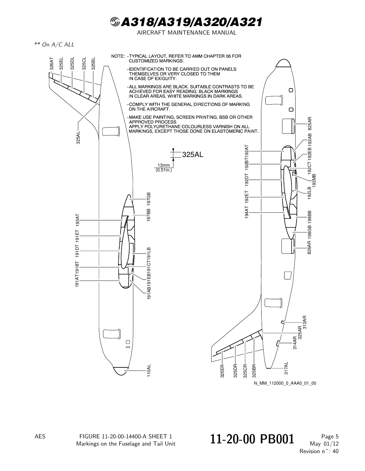
  • 11-20-00 Exterior Placards and Markings: blanking of hoisting points; markings on the fuselage and tail unit, fuselage, THS, left and right wings, engine pylons and cowls
  • 11-21-00 Fuselage: lifting and shoring points; leveling points; air-conditioning skin valves, LP ground connection, pack 1 and 2 inlets/outlets, external air-supply caution; external power receptacle; THS incidence and elevator/rudder neutral-position triangle; magnetic level indicators, APU fuel drain and fuel panel; blue and yellow hydraulic ground connections, reservoir filling and hydraulics-compartment / main-gear-door markings; flight-recorder markings; nose-gear leg-door markings; forward and aft static ports; oxygen discharge; HP ground connection; toilet service doors and panels, potable-water drain and service panels; passenger/crew doors, emergency exits, cargo and avionics doors 811/812/822/824, lower access door, bulk cargo door, markings inside main landing-gear doors; fuselage maintenance and breaking-point markings
  • 11-22-00 Main and Nose Landing Gear: tire inflating-pressure placards and identification labels with the aircraft on wheels; grounding-point locations on nose and main landing gear
  • 11-23-00 Wings: jacking points; hoisting points; flap and slat extension-angle markings; cover-inspection markings on RH and LH wings; flap track 3 and 4 markings; wing upper- and lower-surface fuel markings; DO NOT WALK OUTSIDE THIS AREA, escape-area and escape-rope-bracket markings
  • 11-24-00 Pylons and Cowl Doors: EXTINGUISHER markings on the pylons; engine air-intake L/R; fan cowl and thrust-reverser L/R; nacelle R side; inboard fan-cowl strakes; safe areas and distances L/R; engine leasing-plate location
  • 11-25-00 Stabilizers: hoisting points; horizontal-stabilizer markings; elevator weight-record plate and the task to record elevator weight
  • 11-31-00 Cockpit: air-conditioning, electrical-power, communications (hand mic, headset, boomset, SELCAL registration), equipment/furnishings, fire-extinguisher, flight-controls and speed-limit and pedal markings; rain-repellent reservoir; panels 49VU, 120VU, 11VU MTOW reversible placard, INOP labels on 130VU/131VU; landing-gear, compass-correction and standby-compass, oxygen-mask and smoke-hood markings
  • 11-32-00 Cabin: owner and manufacturer placards; communication-system markings; interior placards for attendant seats, lavatory A door, stowage and partitions, overhead bins, lavatory units and doors, baby nursing table, call and reading-light panels, emergency escape slide Z160; panels 2042VU, 2000VU, 2001VU and sockets; water system; passenger/crew doors, slide armed/disarmed indication, emergency-exit doors; seat-track markings
  • 11-33 / 11-34 / 11-35 / 11-36 / 11-37 / 11-42: battery-bracket and oxygen-bottle markings; nose landing-gear door markings; forward and aft cargo sidewall linings Z131/Z132/Z151/Z152 with max loading-height notes for A319, A320 and A321; potable-water tank; FWD cargo door-selector access panel; APU compartment and access-door markings; additional lavatory-door and call-panel placard figures

IMAGES PREVIEW

Airbus A318 A319 A320 A321 AMM Chapter 11 Placards and Markings AES Revision 40 May 2012 — PDF page 1 preview
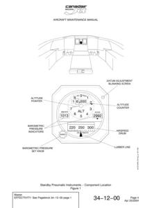
Airbus A318 A319 A320 A321 AMM Chapter 11 Placards and Markings AES Revision 40 May 2012 — PDF page 21 preview
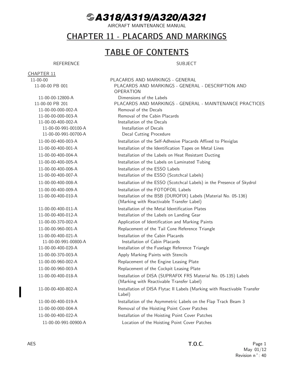
Airbus A318 A319 A320 A321 AMM Chapter 11 Placards and Markings AES Revision 40 May 2012 — PDF page 70 preview

Taken together, those sections give a technician the illustrated location of each marking plus the bonding, cutting, painting and replacement method that belongs to that marking family. The Airbus A318 A319 A320 A321 AMM Chapter 11 Placards and Markings AES Revision 40 May 2012 is therefore a restoration and compliance chapter, not a systems troubleshooting chapter.

Label Families and Standard Dimensions

Standard type No.1 and No.2 labels are plastic with white letters on a black matt finish. Type No.3 FOTOFOIL labels are 0.076 mm (0.002 in.) metal foil specified for Skydrol zones, again with white letters on black matt finish. Figure 11-00-00-12800-A publishes seven standard sizes used across the fleet:

  • Code A – 20 × 6 mm, letter height 3.2 mm / 0.125 in., electrical identification in boxes and panels (example 20 FV 2)
  • Code B – 30 × 8 mm, letter height 4 mm / 0.157 in., electrical identification away from boxes or panels (example 110 PP)
  • Code C – 40 × 10 mm, letter height 6.4 mm / 0.251 in., identification on racks, boxes and panels (example 120 VU)
  • Code D – 20 × 8 mm, letter height 4 mm / 0.157 in., hydraulic-system components (example 1221)
  • Codes E, F and G – 35 × 8 mm, 45 × 10 mm and 45 × 15 mm functional-description labels with 3.2 mm / 0.125 in. letter height

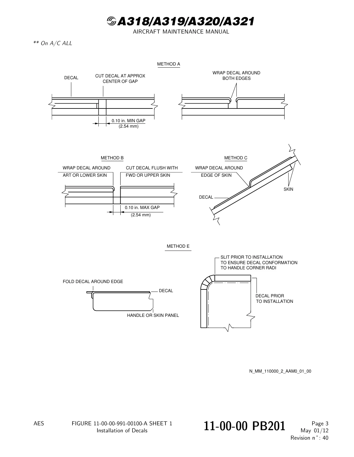
Decal application across moving joints uses a 2.53 mm (0.0996 in.) / 2.54 mm (0.10 in.) gap rule: Method A cuts the film at the centre of a larger gap and wraps both edges; Method B cuts flush with the forward or upper skin on a smaller gap; Method C wraps continuously around a lap-joint edge; Method E slits the film at handle corner radii before wrap. A thin-blade cutter is used against a support plate of at least 0.6 mm metal or 2 mm hard plastic so the aircraft skin is not scribed. Pressure-sensitive polyester film over protruding fasteners is cut away to fastener size; film over pressurized areas is punctured at each rivet. Adhesive on those cut edges is allowed to cure for 1/2 hour before sealing.

Installation and Removal Tasks

Maintenance practices in 11-00-00 PB201 walk through each label chemistry rather than treating every sticker the same. Decals are stripped with Scotch Brite pads (Material No. 19-011) and grade-240 emery after masking, then the topcoat is restored per TASK 51-75-12-300-003-A. Cabin placards are lifted with a plastic scraper only; residual glue is wiped with lint-free cotton (19-003) soaked in dry-cleaning solvent (11-002). Self-adhesive placards on Plexiglas are degreased with the same solvent, started from a 10 mm peeled edge, and smoothed from the centre out without touching the adhesive face.

Identification tapes on metal lines are cut about 5 mm longer than the circumference, cleaned with 1.1.1-trichloroethane (11-004), MEK (11-003) or cleaning solvent (11-016), overlapped, then overcoated with two coats of structure paint (16-003) extending about 10 mm past the tape edge. Damaged paint is touched with external decoration paint (16-016) so hydraulic fluid cannot attack the adhesive. Labels on silicone-impregnated heat-resistant ducting use adhesive sealant 08-004; Viton-coated fabric first receives an MB primer coat that must dry 30 minutes. Laminated tubing uses a peel-and-smooth bond after the same 11-004 degrease.

Complete PDF Bookmark Tree

Complete Bookmarks

The complete bookmarks in the “Airbus A318 A319 A320 A321 AMM Chapter 11 Placards and Markings AES Revision 40 May 2012” are as follows:

Manual Front Matter
Chapter 05 – TIME LIMITS – MAINTENANCE CHECKS
Chapter 06 – DIMENSIONS AND AREAS
Chapter 07 – LIFTING AND SHORING
Chapter 08 – LEVELING AND WEIGHING
Chapter 09 – TOWING AND TAXIING
Chapter 10 – PARKING, MOORING, STORAGE & RETURN TO SERVICE
Chapter 11 – PLACARDS AND MARKINGSp. 1
Table of Contentsp. 1
11-00 – PLACARDS AND MARKINGS – GENERALp. 11
11-00-00 – PLACARDS AND MARKINGS – GENERALp. 11
11-00-00 PB 001 CONF 00 – PLACARDS AND MARKINGS – GENERAL – DESCRIPTION AND OPERATIONp. 11
Generalp. 11
Labelsp. 12
Label Replacementp. 13
Figure 11-00-00-12800-A – Dimensions of the Labelsp. 14
11-00-00 PB 201 CONF 00 – PLACARDS AND MARKINGS – GENERAL – MAINTENANCE PRACTICESp. 15
11-00-00-000-002-A – Removal of the Decalsp. 15
11-00-00-000-003-A – Removal of the Cabin Placardsp. 17
11-00-00-400-002-A – Installation of the Decalsp. 19
Figure 11-00-00-991-00100-A – Installation of Decalsp. 21
Figure 11-00-00-991-00700-A – Decal Cutting Procedurep. 22
11-00-00-400-003-A – Installation of the Self-Adhesive Placards Affixed to Plexiglasp. 23
11-00-00-400-001-A – Installation of the Identification Tapes on Metal Linesp. 24
11-00-00-400-004-A – Installation of the Labels on Heat Resistant Ductingp. 25
11-00-00-400-005-A – Installation of the Labels on Laminated Tubingp. 26
11-00-00-400-006-A – Installation of the ESSO Labelsp. 27
11-00-00-400-007-A – Installation of the ESSO (Scotchcal Labels)p. 28
11-00-00-400-008-A – Installation of the ESSO (Scotchcal Labels) in the Presence of Skydrolp. 29
11-00-00-400-009-A – Installation of the FOTOFOIL Labelsp. 30
11-00-00-400-010-A – Installation of the BSB (DUROFIX) Labels (Material No. 05-136) (Marking with Reactivable Transfer Label)p. 31
11-00-00-400-011-A – Installation of the Metal Identification Platesp. 34
11-00-00-400-012-A – Installation of the Labels on Landing Gearp. 36
11-00-00-370-002-A – Application of Identification and Marking Paintsp. 38
11-00-00-960-001-A – Replacement of the Tail Cone Reference Trianglep. 40
11-00-00-400-021-A – Installation of the Cabin Placardsp. 43
Figure 11-00-00-991-00800-A – Installation of Cabin Placardsp. 45
11-00-00-400-020-A – Installation of the Fuselage Reference Trianglep. 46
11-00-00-370-003-A – Apply Marking Paints with Stencilsp. 48
11-00-00-960-002-A – Replacement of the Engine Leasing Platep. 50
11-00-00-960-003-A – Replacement of the Cockpit Leasing Platep. 53
11-00-00-400-018-A – Installation of DISA (SUPRAFIX FRS Material No. 05-135) Labels (Marking with Reactivable Transfer Label)p. 54
11-00-00-400-802-A – Installation of DISA Flytac II Labels (Marking with Reactivable Transfer Label)p. 57
11-00-00-400-019-A – Installation of the Asymmetric Labels on the Flap Track Beam 3p. 59
11-00-00-000-004-A – Removal of the Hoisting Point Cover Patchesp. 61
11-00-00-400-022-A – Installation of the Hoisting Point Cover Patchesp. 63
Figure 11-00-00-991-00900-A – Location of the Hoisting Point Cover Patchesp. 65
11-20 – EXTERIOR PLACARDS AND MARKINGSp. 66
11-20-00 – EXTERIOR PLACARDS AND MARKINGSp. 66
11-20-00 PB 001 CONF 00 – EXTERIOR PLACARDS AND MARKINGS – DESCRIPTION AND OPERATIONp. 66
Generalp. 66
Markings of the Hoisting Pointsp. 67
Markings on Access Panels and Doors necessaryp. 68
Figure 11-20-00-12300-B – Blanking of the Hoisting Pointsp. 69
Figure 11-20-00-14400-A – Markings on the Fuselage and Tail Unitp. 70
Figure 11-20-00-14500-A – Markings on the Fuselagep. 71
Figure 11-20-00-14600-A – Markings on the THSp. 72
Figure 11-20-00-14700-A – Markings on the L Wingp. 73
Figure 11-20-00-14800-A – Markings on the R Wingp. 75
Figure 11-20-00-14900-A – Markings on the Engine Pylons and Cowlsp. 77
11-21 – FUSELAGEp. 79
11-21-00 – FUSELAGEp. 79
11-21-00 PB 001 CONF 00 – FUSELAGE – DESCRIPTION AND OPERATIONp. 79
Generalp. 79
11-21-07 – LIFTING AND SHORINGp. 80
11-21-07 PB 001 CONF 00 – LIFTING AND SHORING – DESCRIPTION AND OPERATIONp. 80
Generalp. 80
Figure 11-21-07-11500-D – Markings of the Lifting and Shoring Pointsp. 81
Figure 11-21-07-11500-F – Markings of the Lifting and Shoring Pointsp. 82
11-21-08 – LEVELING AND WEIGHINGp. 83
11-21-08 PB 001 CONF 00 – LEVELING AND WEIGHING – DESCRIPTION AND OPERATIONp. 83
Generalp. 83
Figure 11-21-08-11500-A – Markings of the Leveling Pointsp. 84
11-21-21 – AIR CONDITIONINGp. 85
11-21-21 PB 001 CONF 00 – AIR CONDITIONING – DESCRIPTION AND OPERATIONp. 85
Generalp. 85
Figure 11-21-21-13600-P – Markings of the Skin Air Inlet and Outlet Valvesp. 86
Figure 11-21-21-13700-D – Markings of the LP Ground Connectionp. 87
Figure 11-21-21-13700-G – Markings of the LP Ground Connectionp. 88
Figure 11-21-21-13800-D – Markings of the Air Inlet and Outlet of the Packs 1 and 2p. 89
Figure 11-21-21-13800-O – Markings of the Air Inlet of the Packs 1 and 2p. 90
Figure 11-21-21-13800-R – Markings of the Air Inlet of the Packs 1 and 2p. 91
Figure 11-21-21-14100-A – Markings of the External Air-Supply Cautionp. 92
11-21-24 – ELECTRICAL POWERp. 93
11-21-24 PB 001 CONF 00 – ELECTRICAL POWER – DESCRIPTION AND OPERATIONp. 93
Generalp. 93
Figure 11-21-24-11500-D – Markings of the External Power Receptaclep. 94
Figure 11-21-24-11500-K – Markings of the External Power Receptaclep. 95
11-21-27 – FLIGHT CONTROLSp. 96
11-21-27 PB 001 CONF 00 – FLIGHT CONTROLS – DESCRIPTION AND OPERATIONp. 96
Generalp. 96
Figure 11-21-27-12100-A – Markings for the THS Incidencep. 97
Figure 11-21-27-12200-A – Location of the Elevator and Rudder Neutral Position Trianglep. 98
11-21-28 – FUELp. 99
11-21-28 PB 001 CONF 00 – FUEL – DESCRIPTION AND OPERATIONp. 99
Generalp. 99
Figure 11-21-28-12100-C – Markings of the Magnetic Level Indicators and APU Fuel Drainp. 100
Figure 11-21-28-12100-G – Markings of the Magnetic Level Indicators and APU Fuel Drainp. 101
Figure 11-21-28-12200-A – Markings of the Fuel Panelp. 102
Figure 11-21-28-12200-J – Markings of the Fuel Panelp. 103
Figure 11-21-28-12300-A – Markings on the APU Fuel Drainp. 104
11-21-29 – HYDRAULIC POWERp. 105
11-21-29 PB 001 CONF 00 – HYDRAULIC POWER – DESCRIPTION AND OPERATIONp. 105
Generalp. 105
Figure 11-21-29-13300-I – Markings for the Hydraulic Ground Connection of the Blue Systemp. 106
Figure 11-21-29-13300-O – Markings for the Hydraulic Ground Connection of the Blue Systemp. 107
Figure 11-21-29-13500-G – Markings for the Hydraulic Reservoir Fillingp. 108
Figure 11-21-29-13500-N – Markings of the Hydraulic Reservoir Fillingp. 109
Figure 11-21-29-13600-D – Markings for the Hydraulic Ground Connection of the Yellow Systemp. 110
Figure 11-21-29-13600-G – Markings for the Hydraulic Ground Connection of the Yellow Systemp. 111
Figure 11-21-29-13700-D – Markings for the Hydraulics Compartment (Blue System) and Main Gear Doorsp. 112
Figure 11-21-29-13700-E – Markings for the Hydraulics Compartment (Blue System) and Main Gear Doorsp. 113
Figure 11-21-29-13800-D – Markings for the Hydraulics Compartment (Yellow System) and Main Gear Doorsp. 114
Figure 11-21-29-13800-E – Markings for the Hydraulics Compartment (Yellow System) and Main Gear Doorsp. 115
11-21-31 – INDICATING/RECORDING SYSTEMSp. 116
11-21-31 PB 001 CONF 00 – INDICATING/RECORDING SYSTEMS – DESCRIPTION AND OPERATIONp. 116
Generalp. 116
Figure 11-21-31-11500-A – Flight Recorder Markingsp. 117
Figure 11-21-31-11500-D – Flight Recorder Markingsp. 118
11-21-32 – LANDING GEARp. 119
11-21-32 PB 001 CONF 00 – LANDING GEAR – DESCRIPTION AND OPERATIONp. 119
Generalp. 119
Figure 11-21-32-12100-R – Markings on the Nose Gear Leg Doorp. 120
Figure 11-21-32-12100-W – Markings on the Nose Gear Leg Doorp. 121
11-21-34 – NAVIGATIONp. 122
11-21-34 PB 001 CONF 00 – NAVIGATION – DESCRIPTION AND OPERATIONp. 122
Generalp. 122
Figure 11-21-34-12400-K – Markings of the Forward and Aft Static Portsp. 123
Figure 11-21-34-12400-AY – Markings of the Forward and Aft Static Portsp. 124
11-21-35 – OXYGENp. 125
11-21-35 PB 001 CONF 00 – OXYGEN – DESCRIPTION AND OPERATIONp. 125
Generalp. 125
Figure 11-21-35-11500-A – Markings of the Oxygen Dischargep. 126
11-21-36 – PNEUMATICp. 127
11-21-36 PB 001 CONF 00 – PNEUMATIC – DESCRIPTION AND OPERATIONp. 127
Generalp. 127
Figure 11-21-36-11500-E – Markings of the HP Ground Connectionp. 128
Figure 11-21-36-11500-N – Markings of the HP Ground Connectionp. 129
11-21-38 – WATER/WASTEp. 130
11-21-38 PB 001 CONF 00 – WATER/WASTE – DESCRIPTION AND OPERATIONp. 130
Generalp. 130
Figure 11-21-38-14900-A – Markings on the Aft Toilet Service Doorp. 131
Figure 11-21-38-14900-E – Markings on the AFT Toilet Service Doorp. 132
Figure 11-21-38-15000-T – Markings on the Toilet Service Panelsp. 133
Figure 11-21-38-15100-D – Markings on the Potable-Water Drain-Panelp. 134
Figure 11-21-38-15200-A – Markings on the Potable-Water Service-Panelp. 135
Figure 11-21-38-15200-D – Markings on the Potable-Water Service-Panelp. 136
Figure 11-21-38-15300-A – Markings on the Potable-Water Panelp. 137
Figure 11-21-38-15300-B – Markings on the Potable-Water Panelp. 138
Figure 11-21-38-15400-E – Markings on the Potable-Water Drain Panelp. 139
Figure 11-21-38-15500-D – Markings on the Potable-Water Service Panelp. 140
Figure 11-21-38-15600-A – Markings on the Potable-Water Panelp. 141
11-21-52 – DOORSp. 142
11-21-52 PB 001 CONF 00 – DOORS – DESCRIPTION AND OPERATIONp. 142
Generalp. 142
Figure 11-21-52-14900-O – Markings on the Passenger/Crew Doorsp. 144
Figure 11-21-52-14900-B0 – Markings on the Passenger/Crew Doorsp. 146
Figure 11-21-52-15000-A – Markings on the Emergency Exitsp. 148
Figure 11-21-52-15000-AO – Markings on the Emergency Exitsp. 149
Figure 11-21-52-15100-AM – Markings on the Forward and Aft Cargo Compartment Doorsp. 150
Figure 11-21-52-15100-BY – Markings on the Forward and Aft Cargo Compartment Doorsp. 153
Figure 11-21-52-15200-A – Markings on the Avionics Compartment Door 812p. 156
Figure 11-21-52-15200-F – Markings on the Avionics Compartment Door 812p. 157
Figure 11-21-52-15300-L – Markings on the Cargo Door Control-Panelp. 158
Figure 11-21-52-15300-R – Markings on the Cargo Door Control-Panelp. 159
Figure 11-21-52-15600-A – Markings on the Avionics Compartment Door 811p. 160
Figure 11-21-52-15600-E – Markings on the Avionics Compartment Door 811p. 161
Figure 11-21-52-15700-A – Markings on the Avionics Compartment Door 822p. 162
Figure 11-21-52-15700-E – Markings on the Avioincs Compartment Door 822p. 163
Figure 11-21-52-15800-D – Markings on the Avionics Compartment Door 824p. 164
Figure 11-21-52-15800-E – Markings on the Avionics Compartment Door 824p. 165
Figure 11-21-52-15900-D – Markings on the Lower Access Doorp. 166
Figure 11-21-52-15900-I – Markings on the Lower Access Doorp. 167
Figure 11-21-52-16000-Y – Markings on the Bulk Cargo-Compartment Doorp. 168
Figure 11-21-52-16000-AN – Markings on the Bulk Cargo-Compartment Doorp. 170
Figure 11-21-52-16100-B – Markings Inside the Main Landing Gear Doorsp. 172
11-21-53 – FUSELAGEp. 174
11-21-53 PB 001 CONF 00 – FUSELAGE – DESCRIPTION AND OPERATIONp. 174
Generalp. 174
Figure 11-21-53-13600-D – Markings on the Fuselage – Maintenancep. 175
Figure 11-21-53-13600-I – Markings on the Fuselage – Maintenancep. 176
Figure 11-21-53-13700-A – Markings on the Fuselage – Breaking Pointsp. 177
11-22 – MAIN AND NOSE LANDING GEARp. 178
11-22-00 – MAIN AND NOSE LANDING GEARp. 178
11-22-00 PB 001 CONF 00 – MAIN AND NOSE LANDING GEAR – DESCRIPTION AND OPERATIONp. 178
Generalp. 178
11-22-32 – LANDING GEARp. 179
11-22-32 PB 001 CONF 00 – LANDING GEAR – DESCRIPTION AND OPERATIONp. 179
Generalp. 179
Figure 11-22-32-11800-A – Tire Inflating Pressure Placard on the Main Landing Gearp. 180
Figure 11-22-32-12600-N – Identification Labels – tire Inflating Pressure with Aircraft on Wheels Nose Landing Gearp. 181
Figure 11-22-32-13100-T – Identification Labels – Tire Inflating Pressure with Aircraft on Wheels Main Landing Gearp. 182
Figure 11-22-32-13100-Y – Identification Labels – Tire Inflating Pressure with Aircraft on Wheels Main Landing Gearp. 183
Figure 11-22-32-13500-A – Identification labels of the tire inflating pressure, aircraft on wheels, on the main landing gear.p. 184
Figure 11-22-32-13900-A – Location of the Grounding Point on the Nose Landing Gearp. 185
Figure 11-22-32-14200-A – Location of the Grounding Point on the Main Landing Gearp. 186
11-23 – WINGSp. 187
11-23-00 – WINGSp. 187
11-23-00 PB 001 CONF 00 – WINGS – DESCRIPTION AND OPERATIONp. 187
Generalp. 187
11-23-07 – LIFTING AND SHORINGp. 188
11-23-07 PB 001 CONF 00 – LIFTING AND SHORING – DESCRIPTION AND OPERATIONp. 188
Generalp. 188
Figure 11-23-07-11500-A – Markings of the Jacking Pointsp. 189
11-23-27 – FLIGHT CONTROLSp. 190
11-23-27 PB 001 CONF 00 – FLIGHT CONTROLS – DESCRIPTION AND OPERATIONp. 190
Generalp. 190
Figure 11-23-27-13100-A – Markings of the Hoisting Pointsp. 191
Figure 11-23-27-13200-K – Markings of the Flap Extension Anglep. 192
Figure 11-23-27-13300-K – Markings of the Slat Extension Anglep. 193
Figure 11-23-27-13900-B – Marking on Cover Inspection – RH Wingp. 194
Figure 11-23-27-14000-B – Marking on Cover Inspection – LH Wingp. 195
Figure 11-23-27-14100-H – Marking on Flap Track 3p. 196
Figure 11-23-27-14100-J – Marking on Flap Track 3 and 4p. 197
11-23-28 – FUELp. 198
11-23-28 PB 001 CONF 00 – FUEL – DESCRIPTION AND OPERATIONp. 198
Generalp. 198
Figure 11-23-28-12700-A – Markings on the Wing Upper Surfacep. 199
Figure 11-23-28-12800-F – Markings on the Wing Lower Surface (Left Wing)p. 200
Figure 11-23-28-12900-A – Markings on the Wing Lower Surface (Right Wing)p. 201
11-23-57 – WINGSp. 202
11-23-57 PB 001 CONF 00 – WINGS – DESCRIPTION AND OPERATIONp. 202
Generalp. 202
Figure 11-23-57-11800-A – DO NOT WALK OUTSIDE THIS AREA Markings on the Wingsp. 203
Figure 11-23-57-11800-E – DO NOT WALK OUTSIDE THIS AREA Markings on the Wingsp. 204
Figure 11-23-57-11900-C – Markings of the Escape Areap. 205
Figure 11-23-57-12000-A – Markings of the Escape Rope Bracketp. 206
11-24 – PYLONS AND COWL DOORSp. 207
11-24-00 – PYLONS AND COWL DOORSp. 207
11-24-00 PB 001 CONF 00 – PYLONS AND COWL DOORS – DESCRIPTION AND OPERATIONp. 207
Generalp. 207
11-24-26 – FIRE PROTECTIONp. 208
11-24-26 PB 001 CONF 00 – FIRE PROTECTION – DESCRIPTION AND OPERATIONp. 208
Generalp. 208
Figure 11-24-26-11500-A – EXTINGUISHER Markings on the Pylonsp. 209
Figure 11-24-26-11600-A – EXTINGUISHER Markings on the Pylonsp. 210
11-24-71 – POWER PLANTp. 211
11-24-71 PB 001 CONF 00 – POWER PLANT – DESCRIPTION AND OPERATIONp. 211
Generalp. 211
Descriptionp. 212
Item Descriptionp. 213
Figure 11-24-71-16300-B – Markings on Engine Air Intake – L Sidep. 214
Figure 11-24-71-16400-B – Markings on Engine Air Intake – R Sidep. 215
Figure 11-24-71-16500-B – Markings on Fan Cowl and Thrust Reverser – L Sidep. 216
Figure 11-24-71-16500-V – Markings on Fan Cowl and Thrust Reverser – L Sidep. 217
Figure 11-24-71-16600-B – Markings on Fan Cowl and Thrust Reverser – R Sidep. 219
Figure 11-24-71-16600-G – Markings on Fan Cowl and Thrust Reverser – R Sidep. 220
Figure 11-24-71-16700-B – Markings on Nacelle R Sidep. 222
Figure 11-24-71-17000-A – Markings of the Inboard Fan Cowl Strakesp. 223
Figure 11-24-71-17100-C – Markings of the Safe Areas and Distances – L Sidep. 224
Figure 11-24-71-17200-C – Markings of the Safe Areas and Distances – R Sidep. 225
Figure 11-24-71-17300-D – Engine Leasing Plate – Locationp. 226
11-25 – STABILIZERSp. 227
11-25-00 – STABILIZERSp. 227
11-25-00 PB 001 CONF 00 – STABILIZERS – DESCRIPTION AND OPERATIONp. 227
Generalp. 227
11-25-27 – FLIGHT CONTROLSp. 228
11-25-27 PB 001 CONF 00 – FLIGHT CONTROLS – DESCRIPTION AND OPERATIONp. 228
Generalp. 228
Figure 11-25-27-11500-A – Markings of the Hoisting Pointsp. 229
11-25-55 – STABILIZERSp. 230
11-25-55 PB 001 CONF 00 – STABILIZERS – DESCRIPTION AND OPERATIONp. 230
Generalp. 230
Figure 11-25-55-12100-A – Markings on the Horizontal Stabilizerp. 231
Figure 11-25-55-12100-E – Markings on the Horizontal Stabilizerp. 232
Figure 11-25-55-12200-B – Markings of the Hoisting Pointsp. 233
Figure 11-25-55-12300-A – Stabilizers-Elevators-Plate to record Weightp. 234
11-25-55 PB 201 CONF 00 – STABILIZERS – MAINTENANCE PRACTICESp. 235
11-25-55-910-001-A – Record the weight of the elevatorp. 235
11-31 – COCKPITp. 239
11-31-00 – COCKPITp. 239
11-31-00 PB 001 CONF 00 – COCKPIT – DESCRIPTION AND OPERATIONp. 239
Generalp. 239
11-31-21 – AIR CONDITIONINGp. 240
11-31-21 PB 001 CONF 00 – AIR CONDITIONING – DESCRIPTION AND OPERATIONp. 240
Generalp. 240
Figure 11-31-21-11500-A – Air Conditioning System Markings in the Cockpitp. 241
11-31-23 – COMMUNICATIONSp. 242
11-31-23 PB 001 CONF 00 – COMMUNICATIONS – DESCRIPTION AND OPERATIONp. 242
Generalp. 242
Figure 11-31-23-11800-A – Hand Mic, Headset and Boomset Markingsp. 243
Figure 11-31-23-11900-A – Placard Registration Selcal Code Markingp. 244
Figure 11-31-23-11900-B – Placard Registration Selcal Code Markingp. 245
11-31-24 – ELECTRICAL POWERp. 246
11-31-24 PB 001 CONF 00 – ELECTRICAL POWER – DESCRIPTION AND OPERATIONp. 246
Generalp. 246
Figure 11-31-24-11500-A – Electrical Power Markings in the Cockpitp. 247
11-31-25 – EQUIPMENT/FURNISHINGSp. 248
11-31-25 PB 001 CONF 00 – EQUIPMENT/FURNISHINGS – DESCRIPTION AND OPERATIONp. 248
Generalp. 248
Figure 11-31-25-13600-A – Markings in the Cockpitp. 249
Figure 11-31-25-13600-D – Markings in the Cockpitp. 250
Figure 11-31-25-13700-C – Markings in the Cockpitp. 251
Figure 11-31-25-13700-K – Markings in the Cockpitp. 252
Figure 11-31-25-14200-A – Owner and/or Manufacturer Plates in the Cockpitp. 253
Figure 11-31-25-14300-A – Disk Stowage Label in the Cockpitp. 254
11-31-26 – FIRE PROTECTIONp. 255
11-31-26 PB 001 CONF 00 – FIRE PROTECTION – DESCRIPTION AND OPERATIONp. 255
Generalp. 255
Figure 11-31-26-11500-E – Fire Extinguisher Markingsp. 256
11-31-27 – FLIGHT CONTROLSp. 257
11-31-27 PB 001 CONF 00 – FLIGHT CONTROLS – DESCRIPTION AND OPERATIONp. 257
Generalp. 257
Figure 11-31-27-12100-F – Flight Controls Markingsp. 258
Figure 11-31-27-12200-A – Flight Controls Markingsp. 259
Figure 11-31-27-12300-A – Speed Limits Markingsp. 260
Figure 11-31-27-12300-F – Speed Limits Markingsp. 261
Figure 11-31-27-12400-B – Pedals Markingsp. 262
11-31-30 – ICE AND RAIN PROTECTIONp. 263
11-31-30 PB 001 CONF 00 – ICE AND RAIN PROTECTION – DESCRIPTION AND OPERATIONp. 263
Generalp. 263
Figure 11-31-30-11500-A – Rain-Repellent Reservoir Markingp. 264
11-31-31 – INDICATING/RECORDING SYSTEMSp. 265
11-31-31 PB 001 CONF 00 – INDICATING/RECORDING SYSTEMS – DESCRIPTION AND OPERATIONp. 265
Generalp. 265
Figure 11-31-31-12700-A – Markings on Panel 49VU and 120VUp. 266
Figure 11-31-31-12900-AB – MTOW Reversible Placard on Panel 11VUp. 267
Figure 11-31-31-13000-A – INOP Labels on Panels 130VU and 131VUp. 269
11-31-32 – LANDING GEARp. 270
11-31-32 PB 001 CONF 00 – LANDING GEAR – DESCRIPTION AND OPERATIONp. 270
Generalp. 270
Figure 11-31-32-11500-C – Landing Gear Markingsp. 271
11-31-34 – NAVIGATIONp. 272
11-31-34 PB 001 CONF 00 – NAVIGATION – DESCRIPTION AND OPERATIONp. 272
Generalp. 272
Figure 11-31-34-12700-A – Markings of the Compass Correction Cardsp. 273
Figure 11-31-34-12900-A – Markings of the Standby Compassp. 274
11-31-35 – OXYGENp. 275
11-31-35 PB 001 CONF 00 – OXYGEN – DESCRIPTION AND OPERATIONp. 275
Generalp. 275
Figure 11-31-35-12100-A – Oxygen Mask Markingp. 276
Figure 11-31-35-12200-D – Smoke Hood Markingp. 277
11-32 – CABINp. 278
11-32-00 – CABINp. 278
11-32-00 PB 001 CONF 00 – CABIN – DESCRIPTION AND OPERATIONp. 278
Generalp. 278
11-32-11 – PLACARDS AND MARKINGSp. 279
11-32-11 PB 001 CONF 00 – PLACARDS AND MARKINGS – DESCRIPTION AND OPERATIONp. 279
Generalp. 279
Figure 11-32-11-12100-O – Owner and Manufacturer Placards.p. 280
Figure 11-32-11-12100-X – Owner and Manufacturer Placardsp. 281
11-32-23 – COMMUNICATIONSp. 282
11-32-23 PB 001 CONF 00 – COMMUNICATIONS – DESCRIPTION AND OPERATIONp. 282
Generalp. 282
Figure 11-32-23-11800-A – Markings of the Communication Systemp. 283
11-32-25 – INTERIOR PLACARDSp. 284
11-32-25 PB 001 CONF 00 – INTERIOR PLACARDS – DESCRIPTION AND OPERATIONp. 284
Generalp. 284
Component Locationp. 285
Figure 11-32-25-11400-DO – Markings of the Cabin Attendant-Seatsp. 287
Figure 11-32-25-11500-A – Placards at Door of Lavatory Ap. 289
Figure 11-32-25-11800-CY – Markings of the Stowage Compartment and Partitionsp. 290
Figure 11-32-25-12100-DJ – Markings of the Passenger Overhead Stowage Compartmentsp. 292
Figure 11-32-25-12300-CJ – Markings of the Lavatory Unitsp. 294
Figure 11-32-25-12300-IU – Markings of the Lavatory Unitsp. 296
Figure 11-32-25-12400-A – Markings for the Baby Nursing Table in Lavatory Ap. 298
Figure 11-32-25-12600-CL – Markings of the Lavatory Doorsp. 299
Figure 11-32-25-12700-CK – Markings of the Passenger Call and Reading-Light-Switch Panelp. 301
Figure 11-32-25-12800-A – Markings for the Emergency Escape Slide, Z160p. 303
Figure 11-32-25-12800-E – Markings for the Emergency Escape Slide, Z160p. 304
11-32-31 – INDICATING/RECORDING SYSTEMSp. 305
11-32-31 PB 001 CONF 00 – INDICATING/RECORDING SYSTEMS – DESCRIPTION AND OPERATIONp. 305
Generalp. 305
Figure 11-32-31-14800-A – Markings of the Panel 2042 VUp. 306
Figure 11-32-31-14900-A – Markings of the Panel 2000 VUp. 307
Figure 11-32-31-15000-A – Markings of the Panel 2001 VUp. 308
Figure 11-32-31-15100-E – Markings of the Socketsp. 309
Figure 11-32-31-15400-B – Markings of the Electrical System in Lavatory Ap. 310
Figure 11-32-31-15700-A – Markings of the Electrical System in Lavatory Dp. 311
11-32-38 – WATER/WASTEp. 312
11-32-38 PB 001 CONF 00 – WATER/WASTE – DESCRIPTION AND OPERATIONp. 312
Generalp. 312
Figure 11-32-38-11500-R – Markings of the Water Systemp. 313
11-32-52 – DOORSp. 314
11-32-52 PB 001 CONF 00 – DOORS – DESCRIPTION AND OPERATIONp. 314
Generalp. 314
Figure 11-32-52-11300-DB – Markings of the Passenger/Crew Doorsp. 315
Figure 11-32-52-11400-A – Markings of the Slide armed/disarmed Indicationp. 317
Figure 11-32-52-11600-CX – Markings of the Emergency Exit Doorsp. 318
11-32-53 – FUSELAGEp. 320
11-32-53 PB 001 CONF 00 – FUSELAGE – DESCRIPTION AND OPERATIONp. 320
Generalp. 320
Figure 11-32-53-11500-A – Markings in the Seat Tracksp. 321
11-33 – AVIONICS COMPARTMENTp. 322
11-33-24 – ELECTRICAL POWERp. 322
11-33-24 PB 001 CONF 00 – ELECTRICAL POWER – DESCRIPTION AND OPERATIONp. 322
Generalp. 322
Figure 11-33-24-11500-A – Marking on Battery Bracketsp. 323
11-33-35 – OXYGENp. 324
11-33-35 PB 001 CONF 00 – OXYGEN – DESCRIPTION AND OPERATIONp. 324
Generalp. 324
Figure 11-33-35-11500-E – Oxygen Bottle Markingsp. 325
11-34 – NOSE AND MAIN LANDING GEAR WELLSp. 326
11-34-32 – LANDING GEARp. 326
11-34-32 PB 001 CONF 00 – LANDING GEAR – DESCRIPTION AND OPERATIONp. 326
Generalp. 326
Figure 11-34-32-11500-A – Nose Landing Gear Doors Markingsp. 327
11-35 – FORWARD CARGO COMPARTMENTp. 328
11-35-00 – FORWARD CARGO COMPARTMENTp. 328
11-35-00 PB 001 CONF 00 – FORWARD CARGO COMPARTMENT – DESCRIPTION AND OPERATIONp. 328
Generalp. 328
11-35-25 – EQUIPMENT/FURNISHINGSp. 329
11-35-25 PB 001 CONF 00 – EQUIPMENT/FURNISHINGS – DESCRIPTION AND OPERATIONp. 329
Generalp. 329
Component Locationp. 330
Figure 11-35-25-12500-F – Markings on the Left Sidewall-Lining, Z131p. 331
Figure 11-35-25-12900-J – Markings on the Right Sidewall-Lining, Z132p. 333
Figure 11-35-25-13300-B – Max. Loading Height Markings on the Left Sidewall-Lining, Z131p. 334
Figure 11-35-25-13700-B – Max. Load Height Markings on the Right Sidewall-Lining, Z132p. 335
11-35-38 – WATER/WASTEp. 336
11-35-38 PB 001 CONF 00 – WATER/WASTE – DESCRIPTION AND OPERATIONp. 336
Generalp. 336
Figure 11-35-38-11500-A – Markings of the Potable Water Tankp. 337
11-35-52 – DOORSp. 338
11-35-52 PB 001 CONF 00 – DOORS – DESCRIPTION AND OPERATIONp. 338
Generalp. 338
Figure 11-35-52-11500-C – Markings of the FWD Cargo-Compartment Door-Selector Access-Panelp. 339
11-35-53 – FUSELAGEp. 340
11-35-53 PB 001 CONF 00 – FUSELAGE – DESCRIPTION AND OPERATIONp. 340
Generalp. 340
Component Locationp. 341
Figure 11-35-53-12500-D – Markings on the Fwd Cargo Compartment-Bulkhead, Z132p. 342
11-36 – AFT CARGO COMPARTMENTp. 343
11-36-00 – AFT CARGO COMPARTMENTp. 343
11-36-00 PB 001 CONF 00 – AFT CARGO COMPARTMENT – DESCRIPTION AND OPERATIONp. 343
Generalp. 343
11-36-25 – EQUIPMENT/FURNISHINGSp. 344
11-36-25 PB 001 CONF 00 – EQUIPMENT/FURNISHINGS – DESCRIPTION AND OPERATIONp. 344
Generalp. 344
Component Locationp. 345
Figure 11-36-25-12500-V – Markings on the Left Sidewall-Lining, Z151p. 346
Figure 11-36-25-12900-D – Markings on the Right Sidewall-Lining, Z152p. 347
Figure 11-36-25-13700-B – Max. Loading Height Markings on the Left Sidewall-Lining, Z151p. 348
Figure 11-36-25-14100-B – Max. Loading Height Markings on the Right Sidewall-Lining, Z152p. 349
11-36-53 – FUSELAGEp. 350
11-36-53 PB 001 CONF 00 – FUSELAGE – DESCRIPTION AND OPERATIONp. 350
Generalp. 350
Component Locationp. 351
Figure 11-36-53-12500-B – Markings of the Aft Cargo Compartment, Z152p. 352
11-37 – WING, REAR FUSELAGE AND TAIL SECTIONSp. 353
11-37-00 – WING, REAR FUSELAGE AND TAIL SECTIONSp. 353
11-37-00 PB 001 CONF 00 – WING, REAR FUSELAGE AND TAIL SECTIONS – DESCRIPTION AND OPERATIONp. 353
Generalp. 353
11-37-21 – AIR CONDITIONINGp. 354
11-37-21 PB 001 CONF 00 – AIR CONDITIONING – DESCRIPTION AND OPERATIONp. 354
Generalp. 354
Figure 11-37-21-11200-A – Marking on the Air Conditioning Systemsp. 355
11-37-49 – APUp. 356
11-37-49 PB 001 CONF 00 – APU – DESCRIPTION AND OPERATIONp. 356
Generalp. 356
Figure 11-37-49-11200-B – Marking on the APU Compartmentp. 357
Figure 11-37-49-11300-A – Markings on the Access Doorp. 358
11-42 – CABINp. 359
11-42-25 – INTERIOR PLACARDSp. 359
11-42-25 PB 001 CONF 00 – INTERIOR PLACARDS – DESCRIPTION AND OPERATIONp. 359
Component Locationp. 359
Figure 11-42-25-14300-A – Placards at Door of Lavatory Ap. 360
Figure 11-42-25-14300-M – Placards at Door of Lavatory Ap. 361
Figure 11-42-25-14700-FL – Markings of the Lavatory Doorsp. 362
Figure 11-42-25-14800-EX – Markings of the Passenger Call and Reading-Light-Switch Panelp. 364
11-52 – CABINp. 367
11-52-25 – INTERIOR PLACARDSp. 367
11-52-25 PB 001 CONF 00 – INTERIOR PLACARDS – DESCRIPTION AND OPERATIONp. 367
Component Locationp. 367
Chapter 12 – SERVICING
Chapter 20 – STANDARD PRACTICES – AIRFRAME
Chapter 21 – AIR CONDITIONING
Chapter 22 – AUTO FLIGHT
Chapter 23 – COMMUNICATIONS
Chapter 24 – ELECTRICAL POWER
Chapter 25 – EQUIPMENT/FURNISHINGS
Chapter 26 – FIRE PROTECTION
Chapter 27 – FLIGHT CONTROLS
Chapter 28 – FUEL
Chapter 29 – HYDRAULIC POWER
Chapter 30 – ICE AND RAIN PROTECTION
Chapter 31 – INDICATING/RECORDING SYSTEMS
Chapter 32 – LANDING GEAR
Chapter 33 – LIGHTS
Chapter 34 – NAVIGATION
Chapter 35 – OXYGEN
Chapter 36 – PNEUMATIC
Chapter 38 – WATER/WASTE
Chapter 46 – INFORMATION SYSTEMS
Chapter 49 – AIRBORNE AUXILIARY POWER
Chapter 51 – STANDARDS PRACTICES AND STRUCTURES
Chapter 52 – DOORS
Chapter 53 – FUSELAGE
Chapter 54 – NACELLES/PYLONS
Chapter 55 – STABILIZERS
Chapter 56 – WINDOWS
Chapter 57 – WINGS
Chapter 70 – (IAE) – STANDARD PRACTICES – ENGINE
Chapter 71 – (IAE) – POWER PLANT
Chapter 72 – (IAE) – ENGINE
Chapter 73 – (IAE) – ENGINE FUEL AND CONTROL
Chapter 74 – (IAE) – IGNITION
Chapter 75 – (IAE) – AIR
Chapter 76 – (IAE) – ENGINE CONTROLS
Chapter 77 – (IAE) – ENGINE INDICATING
Chapter 78 – (IAE) – EXHAUST
Chapter 79 – (IAE) – OIL
Chapter 80 – (IAE) – STARTING

ESSO labels are reactivated with MEK or cleaning solvent on the adhesive film until tacky. Scotchcal labels in a dry zone receive epoxy adhesive 08-001 and a bead of polysulfide fuel-tank sealant 09-001C around the edge. In a Skydrol zone the surface is roughened with grade-360 emery, the factory adhesive is washed off, and bonding compound 08-017 is brushed on with a 30-second press. FOTOFOIL metal foil uses two-component epoxy 08-010 and a temporary tie strap on cylindrical parts until the adhesive is dry. Separate tasks cover BSB DUROFIX Material No. 05-136, DISA SUPRAFIX FRS Material No. 05-135 and DISA Flytac II reactivable transfer labels, metal identification plates, landing-gear labels, stencil-applied marking paints, and the riveted or bonded tail-cone and fuselage reference triangles used after rudder or elevator neutral adjustment (cross-referred to 27-24-00 and 27-34-00).

Exterior, Powerplant and Landing-Gear Figures

The 11-20 and 11-21 figures map markings onto the fuselage, THS, both wings and the engine pylons with 13 mm (0.51 in.) callouts and zone identifiers. Lifting, shoring and leveling points, pack inlets, LP and HP ground connections, the external power receptacle, fuel panel and APU drain, blue and yellow hydraulic ground points and reservoir-filling marks, static ports, and toilet / potable-water service panels are all drawn with colour (black or grey), frame stations and letter sizes. Door figures cover passenger/crew doors, emergency exits, forward and aft cargo doors, bulk cargo door, avionics doors 811, 812, 822 and 824, the lower access door and the inside faces of the main landing-gear doors, many of them flagged REQUIRED BY REGULATION and some carrying bilingual English/Spanish handle instructions.

Landing-gear pages add the tire inflating-pressure placard on the main gear, on-wheels identification labels for nose and main gear, and the black/green grounding-point marks. Wing pages show jacking and hoisting points, flap and slat extension-angle scales, inspection-cover marks, flap-track 3/4 asymmetric offset values, upper- and lower-surface fuel marks including MAX SUCTION / MAX PRESSURE at the refuelling connector, walk-restricted areas and the red escape-area paint on white antislip. Powerplant figures locate air-intake, fan-cowl, thrust-reverser and nacelle marks, inboard fan-cowl strakes, 15 FT / 5 m safe-area distances and the engraved engine leasing plate filled with red paint.

Cockpit, Cabin and Cargo Interiors

Interior coverage in the Airbus A318 A319 A320 A321 AMM Chapter 11 Placards and Markings AES Revision 40 May 2012 runs from the flight deck through the cabin and both cargo holds. Cockpit figures place air-conditioning and electrical-power marks, hand-mic / headset / boomset labels, SELCAL registration on 400VU or 401VU (effectivity 005-099), escape-rope cover marks, owner/manufacturer plates, disk-stowage, portable fire-extinguisher, flight-control and speed-limit placards (values such as 177 KT, 185 KT, 200 KT and 215 KT appear on the illustrated speed-limit cards), pedal PULL TO ADJUST, rain-repellent reservoir caution, high-voltage marks on 49VU and 120VU, the MTOW reversible placard on 11VU, INOP labels on 130VU and 131VU, park-brake and gravity-extension marks, compass-correction cards, standby compass, oxygen mask and smoke hood.

Cabin and cargo figures locate attendant-seat, lavatory, stowage, overhead-bin, baby-nursing-table, call-panel and escape-slide Z160 placards, high-voltage cautions on 2000VU and 2001VU, slide armed/disarmed indication, seat-track zero points referenced to ATA 06-31-53, cargo sidewall linings Z131/Z132 and Z151/Z152, and maximum loading-height marks that the figures themselves restrict as ONLY VALID FOR A319, ONLY VALID FOR A320 or ONLY VALID FOR A321. The potable-water tank figure shows a 200 L / 52 U.S. GALS capacity mark. APU-compartment and access-door figures include the red-pip / red-hole danger instruction on the pin bolt.

Use This Chapter for Marking Restoration

With the Airbus A318 A319 A320 A321 AMM Chapter 11 Placards and Markings AES Revision 40 May 2012 a line or heavy-maintenance technician can identify the correct label family, cut and wrap film across joints and fasteners, bond the specified chemistry (including Skydrol-zone and heat-duct methods), restore painted stencils and reference triangles, and place exterior and interior markings at the frame, zone and colour shown on the AES Rev 40 figures. Using the published dimensions, gap rules, consumable numbers and JAR 25 regulation flags keeps restored markings consistent with the May 01/12 chapter rather than with a guessed size or adhesive. The file is delivered as an instant PDF after payment — no shipping, readable on any device and printable at the bench — so the Chapter 11 task and figure set is available the same day the marking work is scheduled.
Reviews

There are no reviews yet.

Be the first to review “Airbus A318 A319 A320 A321 AMM Chapter 11 Placards and Markings AES Revision 40 May 2012”

What Our Customers Say

★★★★★ Live reviews from customers
Loading customer reviews...
0
    0
    Your Cart
    Your cart is emptyReturn to Shop
    🛒
    Recently Purchased
    🕒 verified order