★ TRUSTED BY 321,897+ PROFESSIONALS WORLDWIDE
🏢
Trusted Business
Verified & Licensed
🛡️
Virus Free Files
100% Safe Downloads
🔒
Secure Payment
SSL Protected
Instant Delivery
Available Immediately
Sale!

Airbus A318 A319 A320 A321 Chapter 05 Time Limits & Maintenance Checks Manual PDF – Rev 40 2012

Original price was: $49.95.Current price is: $29.95.

745-page Airbus A318/A319/A320/A321 Aircraft Maintenance Manual Chapter 05 covering scheduled zonal inspections, unscheduled maintenance checks, abnormal-event inspections, structural leakage testing, aircraft measurement and leveling, stability procedures, and maintenance-related ferry-flight requirements. AES Revision 40, dated May 01/12.

Instant PDF Download
Available immediately
💾
Save to Your Device
Download & keep forever
🛡️
Antivirus Scanned
100% virus-free
🌍
Trusted Worldwide
175,000+ customers

Description

Airbus A318 A319 A320 A321 Chapter 05 Time Limits & Maintenance Checks Manual PDF – Rev 40 2012

This 745-page Airbus A318/A319/A320/A321 Aircraft Maintenance Manual volume contains Chapter 05, Time Limits – Maintenance Checks. It brings together the scheduled zonal inspection instructions and the extensive unscheduled inspection procedures required after abnormal aircraft operation or reported events. The Airbus A318 A319 A320 A321 Chapter 05 Time Limits & Maintenance Checks Manual PDF – Rev 40 2012 is therefore a focused technical reference for maintenance personnel working with the inspection, evaluation and return-to-service requirements contained in ATA Chapter 05.

The scheduled portion of the chapter is organized around aircraft zones and gives accomplishment instructions for zonal inspection tasks. The unscheduled portion addresses conditions that can require immediate inspection or measurement after events such as hard landings, speed exceedances, bird or hail strikes, lightning strikes, tire or brake failures, runway excursions, engine events, high winds and other abnormal operating conditions. Procedures are supported throughout the manual by inspection tables, task references, aircraft-area drawings, component illustrations, definition diagrams and measurement figures.

File Details

  • Manual type: Aircraft Maintenance Manual – Chapter 05, Time Limits – Maintenance Checks
  • Brand / aircraft: Airbus A318, A319, A320 and A321
  • Revision: 40
  • Date: May 01/12
  • Language: English
  • Page count: 745 pages
  • File format: PDF

Scheduled Zonal Maintenance Inspection Coverage

The scheduled-maintenance section provides accomplishment instructions for zonal inspections across the aircraft. Rather than treating inspection as one undifferentiated walk-around, the chapter divides the aircraft into clearly identified areas and gives the applicable inspection/check tasks for those zones. Many procedures specifically include Electrical Wiring Interconnection System (EWIS) general visual inspections as well as access information for panels, doors and compartment structures.

Coverage extends from the radome and avionics areas through the passenger and cargo compartments, center wing, landing-gear bays, powerplant installations, wing structure and tail. Inspection subjects include visible structure, wiring installations, access areas, fairings, doors, nacelles, pylons, control-surface areas and other equipment contained within the defined aircraft zones.

Unscheduled and Abnormal-Event Inspections

A major part of this Airbus A318/A319/A320/A321 Chapter 05 manual is devoted to inspections required after abnormal events. These procedures go well beyond a simple list of affected components. Depending on the event, the manual gives job setup information, inspection phases, specific aircraft areas to examine, damage criteria, task cross-references, follow-on actions and close-up requirements.

The hard and hard-overweight landing material, for example, includes landing classification information and inspection procedures for aircraft structure, landing gear, wings, engine and pylon interfaces and other critical areas. The manual distinguishes inspection requirements according to the reported event and available aircraft data, and contains supporting illustrations for critical structure and landing-gear components.

Other event-driven procedures address landing-gear limiting-speed exceedance, flap/slat overspeed, bird and hail strike, tire burst or tread throw, wheel failure, brake emergency application or overheat, excessive turbulence, VMO/MMO exceedance, lightning strike, engine bird strike or slush ingestion, tail runway impact, nose-landing-gear towing overload, steering-angle exceedance, runway or taxiway excursion, dust and volcanic-ash exposure, engine failure, impacts to engine cowls, fluid spillage, abnormal passenger/crew door movement, main-landing-gear vibration at touchdown, engine windmilling, wing-tip or fence impact, overweight taxiing, very high winds and high lateral loads.

Inspection Drawings and Technical References

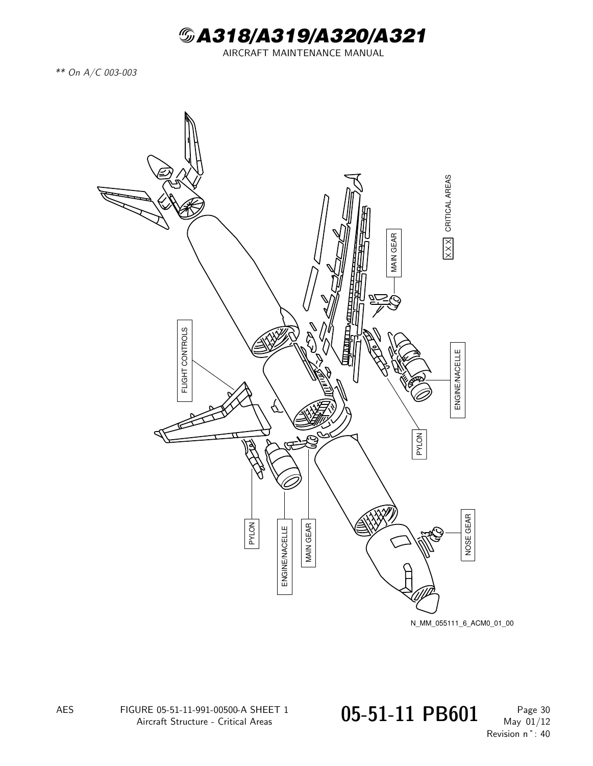
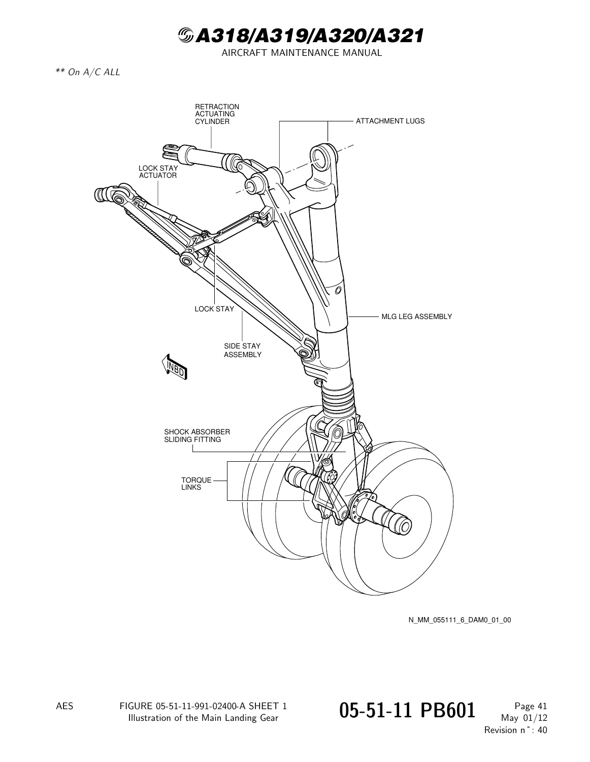
The Chapter 05 procedures are accompanied by pictorial material that helps identify the areas and assemblies involved in inspection. Examples include aircraft-structure critical-area diagrams, engine-to-pylon and pylon-to-wing attachment illustrations, inlet cowl and fan-cowl details, thrust-reverser fittings, main and nose landing-gear illustrations, fuselage and center-section views, antenna and probe locations, engine nacelle drawings, wing-tip illustrations and measurement-point diagrams.

IMAGES PREVIEW

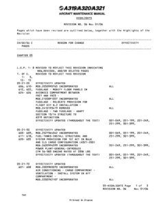
Airbus A318 A319 A320 A321 Chapter 05 Time Limits & Maintenance Checks Manual PDF - Rev 40 2012 — PDF page 17 preview
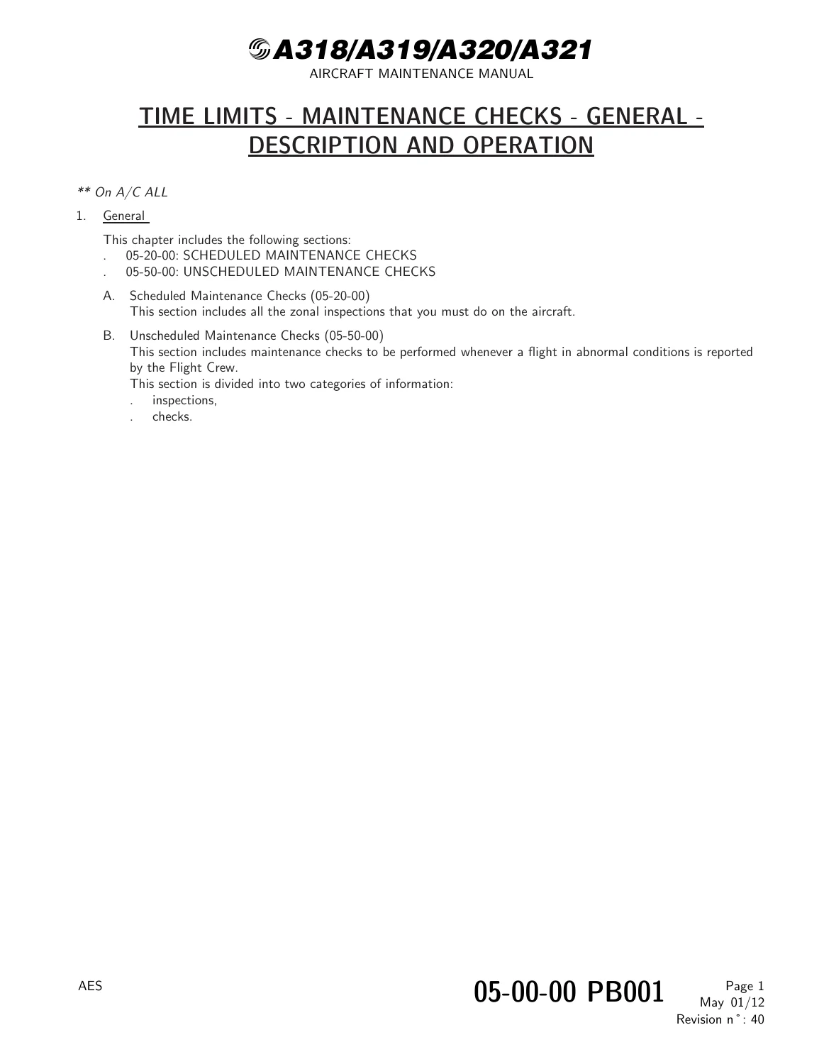
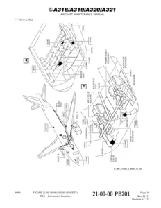
Airbus A318 A319 A320 A321 Chapter 05 Time Limits & Maintenance Checks Manual PDF - Rev 40 2012 — PDF page 352 preview
Airbus A318 A319 A320 A321 Chapter 05 Time Limits & Maintenance Checks Manual PDF - Rev 40 2012 — PDF page 363 preview

These figures are particularly useful where an abnormal event requires inspection of a defined structural region rather than a general external check. The manual also references related AMM tasks when additional opening, removal, system operation, testing, defueling, access or corrective work is required.

Aircraft Measurement, Leakage and Stability Procedures

Chapter 05 also includes procedures used when abnormal operation or repair makes structural verification necessary. Fuselage pressurization and leakage checks include tests in a repair area at differential pressures of 280 mbar (4.06 psi) and 550 mbar (7.97 psi), together with a procedure for measuring structural leakage.

The leveling and measurement material provides procedures for checking aircraft geometry after abnormal operation. It identifies datum lines and datum points and includes measurement references for the fuselage, wing, horizontal stabilizer, vertical stabilizer, engine pylons and landing gears. Figures include positions of measurement points, dimensional tables, checks of wing and fuselage point variation, vertical-stabilizer verticality, engine-pylon coordinates, landing-gear X/Y positions and main-gear symmetry.

An aircraft-stability section addresses the aircraft on its wheels under dry, wet and icy ground conditions as well as configurations involving jacks, a forward jack, a nose-wheel jack, a single main-gear wheel jack and wheel-change arrangements. The chapter additionally contains demagnetization maintenance practices for external parts of the windshield and sliding-window frames.

Chapters Covered

  • 05-00-00 – Time Limits – Maintenance Checks – General
    • Description and operation
    • Scheduled and unscheduled maintenance-check structure
  • 05-20-00 – Scheduled Maintenance Checks
    • Zonal inspection task numbering and accomplishment instructions
  • 05-21-00 – Zonal Inspection: Lower Half of Fuselage
    • Radome; avionics compartment; forward, aft and bulk cargo compartments; center wing; aft cabin underfloor; belly fairing; air-conditioning and hydraulics compartments
  • 05-22-00 – Zonal Inspection: Upper Half of Fuselage
    • Cockpit; forward cabin utility areas; forward, center and aft passenger compartments; aft cabin utility area
  • 05-23-00 – Zonal Inspection: Stabilizers and Cone/Rear Fuselage
    • Aft fuselage tail section; vertical stabilizer and rudder; trimmable horizontal stabilizer and elevator
  • 05-24-00 – Zonal Inspection: Power Plant, Nacelles and Pylons
    • Engine pylon box and forward fairing; air intake, fan and accessory gearbox; thrust reverser and exhaust section; aft pylon
  • 05-25-00 – Zonal Inspection: Wing
    • Fixed leading edge; flap-track fairings and wing tip; fuel tank; vent surge tank; outboard dry bay; aft/trailing-edge structure; aileron
  • 05-27-00 – Zonal Inspection: Landing Gear and Landing Gear Doors
    • Nose gear and doors; main landing gear and doors
  • 05-28-00 – Zonal Inspection: Doors
    • Avionics doors; cargo doors; passenger/crew doors and emergency exits
  • 05-50-00 – Unscheduled Maintenance Checks
    • Maintenance practices, fluid-leak measurement and quick-dispatch cross-references

    Complete PDF Bookmark Tree

    Complete Bookmarks

    The complete bookmarks in the “Airbus A318 A319 A320 A321 Chapter 05 Time Limits & Maintenance Checks Manual PDF – Rev 40 2012” are as follows:

    Manual Front Matter
    Chapter 05 – TIME LIMITS – MAINTENANCE CHECKSp. 1
    Table of Contentsp. 1
    05-00 – TIME LIMITS – MAINTENANCE CHECKS – GENERALp. 17
    05-00-00 – TIME LIMITS – MAINTENANCE CHECKS – GENERALp. 17
    05-00-00 PB 001 CONF 00 – TIME LIMITS – MAINTENANCE CHECKS – GENERAL – DESCRIPTION AND OPERATIONp. 17
    Generalp. 17
    Time Limits and Maintenance Checksp. 18
    05-20 – SCHEDULED MAINTENANCE CHECKSp. 19
    05-20-00 – SCHEDULED MAINTENANCE CHECKSp. 19
    05-20-00 PB 001 CONF 00 – SCHEDULED MAINTENANCE CHECKS – DESCRIPTION AND OPERATIONp. 19
    Generalp. 19
    05-21 – ZONAL INSPECTION : LOWER HALF OF FUSELAGEp. 20
    05-21-00 – ZONAL INSPECTION : LOWER HALF OF FUSELAGEp. 20
    05-21-00 PB 601 CONF 00 – ZONAL INSPECTION : LOWER HALF OF FUSELAGE – INSPECTION/CHECKp. 20
    05-21-00-200-001-A – Zonal Inspection as far as visible from the Ground of the Lower Half of the Fuselagep. 20
    05-21-00-200-002-A – Zonal Inspection of the Lower Half of the Fuselagep. 21
    05-21-10 – ZONAL INSPECTION : RADOMEp. 22
    05-21-10 PB 601 CONF 00 – ZONAL INSPECTION : RADOME – INSPECTION/CHECKp. 22
    05-21-10-200-001-A – GENERAL VISUAL INSPECTION OF RADOME (EWIS)p. 22
    05-21-20 – ZONAL INSPECTION : AVIONICS COMPARTMENTp. 24
    05-21-20 PB 601 CONF 00 – ZONAL INSPECTION : AVIONICS COMPARTMENT – INSPECTION/CHECKp. 24
    05-21-20-200-001-A – GENERAL VISUAL INSPECTION OF AVIONIC COMPARTMENT (EWIS)p. 24
    05-21-20-200-002-A – Zonal Inspection as far as Visible from the Ground of the Nose Gear Well (Zones 123)p. 25
    05-21-20-200-003-A – GENERAL VISUAL INSPECTION OF LATERAL AVIONIC COMPARTMENT (EWIS)p. 26
    Figure 05-21-20-991-00200-A – Access Doors of the Avionics Compartment (Left Side)p. 28
    Figure 05-21-20-991-00700-A – Access Doors of the Avionics Compartment (Right Side)p. 29
    05-21-20-200-005-A – GENERAL VISUAL INSPECTION OF REAR AVIONIC COMPARTMENT (EWIS)p. 30
    05-21-20-200-007-A – GENERAL VISUAL INSPECTION OF AVIONIC COMPARTMENT (EWIS)p. 31
    05-21-20-200-008-A – GENERAL VISUAL INSPECTION OF LATERAL AVIONIC COMPARTMENT (EWIS)p. 33
    05-21-20-200-010-A – GENERAL VISUAL INSPECTION OF REAR AVIONIC COMPARTMENT (EWIS)p. 35
    Figure 05-21-20-991-00600-A – Sidewall Panels of the Forward Cargo Compartmentp. 37
    05-21-20-200-012-A – GENERAL VISUAL INSPECTION OF NOSE GEAR WELL (EWIS)p. 38
    05-21-30 – ZONAL INSPECTION : FORWARD CARGO COMPARTMENTp. 39
    05-21-30 PB 601 CONF 00 – ZONAL INSPECTION : FORWARD CARGO COMPARTMENT – INSPECTION/CHECKp. 39
    05-21-30-200-001-A – GENERAL VISUAL INSPECTION OF FORWARD CARGO COMPARTMENT (AS FAR AS VISIBLE, IF ACT(S) INSTALLED) (EWIS)p. 39
    05-21-30-200-002-A – GENERAL VISUAL INSPECTION OF UNDERFLOOR BAY OF FWD CARGO COMPARTMENT (EWIS)p. 41
    Figure 05-21-30-991-00300-A – Access Doors of the Lower Section of the Fuselage (Zone 130)p. 43
    05-21-30-200-003-A – GENERAL VISUAL INSPECTION OF BAY BEHIND FWD CARGO COMPARTMENT (EWIS)p. 44
    05-21-30-200-004-A – GENERAL VISUAL INSPECTION OF FORWARD CARGO COMPARTMENT (EWIS)p. 46
    Figure 05-21-30-991-00200-A – Floor and Ceiling Panels of the Forward Cargo Compartmentp. 48
    Figure 05-21-30-991-00100-A – Sidewall Panels of the Forward Cargo Compartmentp. 49
    05-21-30-200-006-A – GENERAL VISUAL INSPECTION OF FORWARD CARGO COMPARTMENT (EWIS)p. 50
    05-21-40 – ZONAL INSPECTION : CENTER WINGp. 52
    05-21-40 PB 601 CONF 00 – ZONAL INSPECTION : CENTER WING – INSPECTION/CHECKp. 52
    05-21-40-200-001-A – GENERAL VISUAL INSPECTION OF CENTER WING BOX (EWIS)p. 52
    05-21-40-200-002-A – GENERAL VISUAL INSPECTION OF ZONE UNDER CABIN FLOOR (EWIS)p. 54
    05-21-40-200-003-A – Zonal Inspection as far as visible from the Ground of the Main Gear Well and the Hydraulics Compartment (Zones 147 and 148)p. 56
    05-21-40-200-004-A – GENERAL VISUAL INSPECTION OF MLG-WELL AND HYDRAULIC COMPARTMENT (EWIS)p. 57
    05-21-40-200-005-A – GENERAL VISUAL INSPECTION OF MLG-WELL AND HYDRAULIC COMPARTMENT (EWIS)p. 59
    05-21-50 – ZONAL INSPECTION : AFT CARGO COMPARTMENTp. 61
    05-21-50 PB 601 CONF 00 – ZONAL INSPECTION : AFT CARGO COMPARTMENT – INSPECTION/CHECKp. 61
    05-21-50-200-001-A – GENERAL VISUAL INSPECTION OF AFT CARGO COMPARTMENT (EWIS)p. 61
    05-21-50-200-002-A – GENERAL VISUAL INSPECTION OF UNDERFLOOR BAY OF AFT CARGO COMPARTMENT (EWIS)p. 63
    05-21-50-200-003-A – Zonal Inspection of Aft Cargo Compartment (EWIS)p. 65
    Figure 05-21-50-991-00200-F – Floor and Ceiling Panels of the Aft Cargo Compartmentp. 67
    Figure 05-21-50-991-00100-A – Sidewall Panels of the Aft Cargo Compartmentp. 68
    05-21-50-200-004-A – GENERAL VISUAL INSPECTION OF AFT CARGO COMPARTMENT (EWIS)p. 69
    05-21-60 – ZONAL INSPECTION : BULK CARGO COMPARTMENTp. 72
    05-21-60 PB 601 CONF 00 – ZONAL INSPECTION : BULK CARGO COMPARTMENT – INSPECTION/CHECKp. 72
    05-21-60-200-001-A – GENERAL VISUAL INSPECTION OF BULK CARGO COMPARTMENT (AS FAR AS VISIBLE, IF ACT IS INSTALLED) (EWIS)p. 72
    05-21-60-200-002-A – GENERAL VISUAL INSPECTION OF UNDERFLOOR BAY OF BULK CARGO COMPARTMENT (EWIS)p. 74
    05-21-60-200-003-A – GENERAL VISUAL INSPECTION OF BULK CARGO COMPARTMENT (EWIS)p. 76
    05-21-60-200-004-A – GENERAL VISUAL INSPECTION OF BULK CARGO COMPARTMENT (EWIS)p. 78
    Figure 05-21-60-991-00100-B – Floor and Ceiling Panels of the Bulk Cargo Compartmentp. 80
    Figure 05-21-60-991-00200-B – Sidewall Panels and Partition of the Bulk Cargo Compartmentp. 81
    05-21-70 – ZONAL INSPECTION : AFT CABIN UNDERFLOOR COMPARTMENTp. 82
    05-21-70 PB 601 CONF 00 – ZONAL INSPECTION : AFT CABIN UNDERFLOOR COMPARTMENT – INSPECTION/CHECKp. 82
    05-21-70-200-001-A – GENERAL VISUAL INSPECTION OF AFT CABIN UNDERFLOOR COMPARTMENT (EWIS)p. 82
    Figure 05-21-70-991-00100-A – Access Doors of the Aft Fuselagep. 84
    05-21-70-200-002-A – GENERAL VISUAL INSPECTION OF AFT CABIN UNDERFLOOR COMPARTMENT (EWIS)p. 85
    05-21-90 – ZONAL INSPECTION : BELLY FAIRING, AIR CONDITIONING AND HYDRAULICS COMPARTMENTSp. 87
    05-21-90 PB 601 CONF 00 – ZONAL INSPECTION : BELLY FAIRING, AIR CONDITIONING AND HYDRAULICS COMPARTMENTS – INSPECTION/CHECKp. 87
    05-21-90-200-001-A – GENERAL VISUAL INSPECTION OF AIR CONDITIONING COMPARTMENT AND FAIRINGS (EWIS)p. 87
    05-21-90-200-003-A – GENERAL VISUAL INSPECTION OF OFFWING ESCAPE SLIDE STOWAGE AREA (EWIS)p. 89
    05-21-90-200-005-A – GENERAL VISUAL INSPECTION OF HYDRAULIC COMPARTMENT AND FAIRINGS (EWIS)p. 91
    Figure 05-21-90-991-00400-A – Hydraulic Compartment Access Doors (195BB and 196BB)p. 92
    05-21-90-200-007-A – GENERAL VISUAL INSPECTION OF REAR FAIRING (EWIS)p. 93
    05-21-90-200-009-A – GENERAL VISUAL INSPECTION OF AIR CONDITIONING COMPARTMENT AND FAIRINGS (EWIS)p. 95
    05-22 – ZONAL INSPECTION : UPPER HALF OF FUSELAGEp. 97
    05-22-00 – ZONAL INSPECTION : UPPER HALF OF FUSELAGEp. 97
    05-22-00 PB 601 CONF 00 – ZONAL INSPECTION : UPPER HALF OF FUSELAGE – INSPECTION/CHECKp. 97
    05-22-00-200-001-A – Zonal Inspection as far as Visible from the Ground of the Upper Half of the Fuselagep. 97
    05-22-00-200-002-A – Zonal Inspection of the Upper Half of the Fuselagep. 98
    05-22-10 – ZONAL INSPECTION : COCKPITp. 99
    05-22-10 PB 601 CONF 00 – ZONAL INSPECTION : COCKPIT – INSPECTION/CHECKp. 99
    05-22-10-200-001-A – GENERAL VISUAL INSPECTION OF COCKPIT (EWIS)p. 99
    Figure 05-22-10-991-00100-A – Access Panels of the Cockpitp. 101
    05-22-10-200-002-A – GENERAL VISUAL INSPECTION OF COCKPIT (EWIS)p. 102
    05-22-20 – ZONAL INSPECTION : FORWARD CABIN UTILITY AREASp. 104
    05-22-20 PB 601 CONF 00 – ZONAL INSPECTION : FORWARD CABIN UTILITY AREAS – INSPECTION/CHECKp. 104
    05-22-20-200-006-A – GENERAL VISUAL INSPECTION OF FWD CABIN UTILITY AREAS INCLUDING FLOOR STRUCTURE (EWIS)p. 104
    05-22-20-200-003-A – GENERAL VISUAL INSPECTION OF FWD CABIN UTILITY AREA OVERHEAD COMPARTMENT (EWIS)p. 107
    05-22-30 – ZONAL INSPECTION : FORWARD PASSENGER COMPARTMENTp. 109
    05-22-30 PB 601 CONF 00 – ZONAL INSPECTION : FORWARD PASSENGER COMPARTMENT – INSPECTION/CHECKp. 109
    05-22-30-200-001-A – GENERAL VISUAL INSPECTION OF FWD PASSENGER COMPARTMENT (EWIS) (INCLUDING FLOOR STRUCTURE)p. 109
    Figure 05-22-30-991-00100-A – Sidewall and Ceiling Panels of the Passenger Compartment (Zones 231-232)p. 112
    Figure 05-22-30-991-00200-A – Sidewall Panels of the Passenger Compartment (Zone 232)p. 113
    05-22-30-200-003-A – GENERAL VISUAL INSPECTION OF FWD PASSENGER OVERHEAD COMPARTMENT (EWIS)p. 114
    05-22-40 – ZONAL INSPECTION : MID PASSENGER COMPARTMENTp. 116
    05-22-40 PB 601 CONF 00 – ZONAL INSPECTION : MID PASSENGER COMPARTMENT – INSPECTION/CHECKp. 116
    05-22-40-200-001-A – GENERAL VISUAL INSPECTION OF CENTER PASSENGER COMPARTMENT (EWIS) (INCLUDING FLOOR STRUCTURE)p. 116
    Figure 05-22-40-991-00100-A – Sidewall and Ceiling Panels of the Center Passenger Compartmentp. 119
    Figure 05-22-40-991-00200-A – Sidewall Panels of the Passenger Compartment (Zone 242)p. 120
    05-22-40-200-003-A – GENERAL VISUAL INSPECTION OF CENTER PASSENGER OVERHEAD COMPARTMENT (EWIS)p. 121
    05-22-50 – ZONAL INSPECTION : AFT PASSENGER COMPARTMENTp. 123
    05-22-50 PB 601 CONF 00 – ZONAL INSPECTION : AFT PASSENGER COMPARTMENT – INSPECTION/CHECKp. 123
    05-22-50-200-001-A – GENERAL VISUAL INSPECTION OF AFT PASSENGER COMPARTMENT (EWIS) (INCLUDING FLOOR STRUCTURE)p. 123
    Figure 05-22-50-991-00100-A – Sidewall and Ceiling Panels of the Aft Passenger Compartment (Zone 251)p. 126
    Figure 05-22-50-991-00200-A – Sidewall Panels of the Passenger Compartment (Zone 252)p. 127
    05-22-50-200-003-A – GENERAL VISUAL INSPECTION OF AFT PASSENGER OVERHEAD COMPARTMENT (EWIS)p. 128
    05-22-60 – ZONAL INSPECTION : AFT CABIN UTILITY AREAp. 130
    05-22-60 PB 601 CONF 00 – ZONAL INSPECTION : AFT CABIN UTILITY AREA – INSPECTION/CHECKp. 130
    05-22-60-200-003-A – Zonal Inspection of the Overhead Compartment of the Aft Cabin (EWIS) (Zones 263 and 264)p. 130
    05-22-60-200-004-A – GENERAL VISUAL INSPECTION OF AFT CABIN UTILITY AREAS INCLUDING FLOOR STRUCTURE (EWIS)p. 132
    05-23 – ZONAL INSPECTION : STABILIZERS AND CONE/REAR FUSELAGEp. 135
    05-23-00 – ZONAL INSPECTION : STABILIZERS AND CONE/REAR FUSELAGEp. 135
    05-23-00 PB 601 CONF 00 – ZONAL INSPECTION : STABILIZERS AND CONE/REAR FUSELAGE – INSPECTION/CHECKp. 135
    05-23-00-200-001-A – Zonal Inspection as far as visible from the ground of the Stabilizers and the Cone/Rear Fuselagep. 135
    05-23-00-200-002-A – Zonal Inspection of Stabilizers and Cone/Rear Fuselagep. 136
    05-23-10 – ZONAL INSPECTION : FUSELAGE TAIL SECTION AFT OF AFT PRESSURE BULKHEADp. 137
    05-23-10 PB 601 CONF 00 – ZONAL INSPECTION : FUSELAGE TAIL SECTION AFT OF AFT PRESSURE BULKHEAD – INSPECTION/CHECKp. 137
    05-23-10-200-001-A – GENERAL VISUAL INSPECTION OF AFT FUSELAGE TAIL SECTION (EWIS)p. 137
    Figure 05-23-10-991-00100-A – Access Provision of the Aft Fuselage Tail Sectionp. 139
    05-23-10-200-002-A – GENERAL VISUAL INSPECTION OF TAIL CONE APU AIR INTAKE AREA (EWIS)p. 140
    05-23-10-200-003-A – GENERAL VISUAL INSPECTION OF TAIL CONE APU AND ACCESSORY COMPARTMENT (EWIS)p. 141
    05-23-10-200-004-A – GENERAL VISUAL INSPECTION OF TAIL CONE APU EXHAUST AREA (EWIS)p. 143
    05-23-20 – ZONAL INSPECTION : VERTICAL STABILIZER AND RUDDERp. 144
    05-23-20 PB 601 CONF 00 – ZONAL INSPECTION : VERTICAL STABILIZER AND RUDDER – INSPECTION/CHECKp. 144
    05-23-20-200-001-A – GENERAL VISUAL INSPECTION OF DORSAL FIN (EWIS)p. 144
    05-23-20-200-002-A – GENERAL VISUAL INSPECTION OF VERTICAL STABILIZER LEADING EDGE (EWIS)p. 146
    05-23-20-200-003-A – GENERAL VISUAL INSPECTION OF VERTICAL STABILIZER SPAR BOX (EWIS)p. 148
    05-23-20-200-004-A – GENERAL VISUAL INSPECTION OF VERTICAL STABILIZER TIP (EWIS)p. 150
    05-23-20-200-005-A – GENERAL VISUAL INSPECTION OF VERTICAL STABILIZER TRAILING EDGE (EWIS)p. 151
    05-23-20-200-006-A – GENERAL VISUAL INSPECTION OF RUDDER (EWIS)p. 153
    05-23-20-200-007-A – GENERAL VISUAL INSPECTION OF VERTICAL STABILIZER TRAILING EDGE (EWIS)p. 155
    05-23-20-200-008-A – GENERAL VISUAL INSPECTION OF RUDDER (EWIS)p. 157
    05-23-30 – ZONAL INSPECTION : TRIMMABLE HORIZONTAL STABILIZER AND ELEVATORp. 159
    05-23-30 PB 601 CONF 00 – ZONAL INSPECTION : TRIMMABLE HORIZONTAL STABILIZER AND ELEVATOR – INSPECTION/CHECKp. 159
    05-23-30-200-001-A – GENERAL VISUAL INSPECTION OF TRIMMABLE HORIZONTAL STABILIZER LEADING EDGE (EWIS)p. 159
    05-23-30-200-002-A – GENERAL VISUAL INSPECTION OF TRIMMABLE HORIZONTAL STABILIZER TIP (EWIS)p. 161
    05-23-30-200-003-A – GENERAL VISUAL INSPECTION OF TRIMMABLE HORIZONTAL STABILIZER SPAR BOX (EWIS)p. 162
    Figure 05-23-30-991-00700-A – Access provision of the Aft Fuselage Tail Sectionp. 164
    05-23-30-200-004-A – GENERAL VISUAL INSPECTION OF TRIMMABLE HORIZONTAL STABILIZER TRAILING EDGE (EWIS)p. 165
    05-23-30-200-005-A – GENERAL VISUAL INSPECTION OF ELEVATOR (EWIS)p. 167
    05-23-30-200-007-A – GENERAL VISUAL INSPECTION OF TRIMMABLE HORIZONTAL STABILIZER TRAILING EDGE (EWIS)p. 169
    05-24 – ZONAL INSPECTION : POWER PLANT, NACELLES AND PYLONSp. 171
    05-24-00 – ZONAL INSPECTION : POWER PLANT, NACELLES AND PYLONSp. 171
    05-24-00 PB 601 CONF 00 – ZONAL INSPECTION : POWER PLANT, NACELLES AND PYLONS – INSPECTION/CHECKp. 171
    05-24-00-200-001-A – Zonal Inspection as far as Visible from the Ground of the Power Plant, the Nacelles and the Pylonsp. 171
    05-24-00-200-002-A – Zonal Inspection of the Power Plant, the Nacelles and the Pylonsp. 172
    05-24-10 – ZONAL INSPECTION : ENGINE PYLON BOX AND FORWARD FAIRINGp. 173
    05-24-10 PB 601 CONF 00 – ZONAL INSPECTION : ENGINE PYLON BOX AND FORWARD FAIRING – INSPECTION/CHECKp. 173
    05-24-10-200-001-A – GENERAL VISUAL INSPECTION OF UPPER FWD PYLON (EWIS)p. 173
    Figure 05-24-10-991-00100-B – Access Panels and Doors of the Left Nacelle (Left Side)p. 175
    Figure 05-24-10-991-00200-B – Access Panels and Doors of the Left Nacelle (Right Side)p. 176
    Figure 05-24-10-991-00300-B – Access Panels and Doors of the Right Nacelle (Left Side)p. 177
    Figure 05-24-10-991-00400-B – Access Panels and Doors of the Right Nacelle (Right Side)p. 178
    05-24-10-200-002-A – GENERAL VISUAL INSPECTION OF LOWER PYLON (EWIS)p. 179
    05-24-30 – ZONAL INSPECTION : ENGINE AIR INTAKE, FAN AND ACCESSORY GEARBOXp. 181
    05-24-30 PB 601 CONF 00 – ZONAL INSPECTION : ENGINE AIR INTAKE, FAN AND ACCESSORY GEARBOX – INSPECTION/CHECKp. 181
    05-24-30-200-001-A – GENERAL VISUAL INSPECTION OF AIR INTAKE LIP (EWIS)p. 181
    Figure 05-24-30-991-00100-C – Access Doors of the Left Nacelle (Left Side)p. 183
    Figure 05-24-30-991-00200-C – Access Doors of the Left Nacelle (Right Side)p. 184
    Figure 05-24-30-991-00300-B – Access Doors of the Right Nacelle (Right Side)p. 185
    Figure 05-24-30-991-00400-B – Access Doors of the Right Nacelle (Left Side)p. 186
    05-24-30-200-002-A – GENERAL VISUAL INSPECTION OF FAN AND ACCESSORY GEAR BOX (EWIS)p. 187
    05-24-30-200-003-A – GENERAL VISUAL INSPECTION OF FAN COWL (EWIS)p. 189
    05-24-50 – ZONAL INSPECTION : ENGINE THRUST REVERSER AND EXHAUST SECTIONp. 191
    05-24-50 PB 601 CONF 00 – ZONAL INSPECTION : ENGINE THRUST REVERSER AND EXHAUST SECTION – INSPECTION/CHECKp. 191
    05-24-50-200-001-A – GENERAL VISUAL INSPECTION OF THRUST REVERSER (EWIS)p. 191
    Figure 05-24-50-991-00100-B – Access Doors of the Left Nacelle (Left Side)p. 194
    Figure 05-24-50-991-00200-B – Access Doors of the Left Nacelle (Right Side)p. 195
    Figure 05-24-50-991-00300-B – Access Doors of the Right Nacelle (Left Side)p. 196
    Figure 05-24-50-991-00400-B – Access Doors of the Right Nacelle (Right Side)p. 197
    05-24-50-200-002-A – GENERAL VISUAL INSPECTION OF HOT SECTION (EWIS)p. 198
    Figure 05-24-50-991-00500-A – HPT Case Flange Locationp. 200
    05-24-70 – ZONAL INSPECTION : ENGINE AFT PYLONp. 201
    05-24-70 PB 601 CONF 00 – ZONAL INSPECTION : ENGINE AFT PYLON – INSPECTION/CHECKp. 201
    05-24-70-200-001-A – GENERAL VISUAL INSPECTION OF PYLON LEADING EDGE AND LOWER FAIRING (EWIS)p. 201
    Figure 05-24-70-991-00100-C – Location of the Access Panels of the Left Nacelle (Left Side)p. 204
    Figure 05-24-70-991-00200-C – Location of the Access Panels of the Left Nacelle (Right Side)p. 205
    Figure 05-24-70-991-00500-C – Location of the Access Panels of the Right Nacelle (Left Side)p. 206
    Figure 05-24-70-991-00600-C – Location of the Access Panels of the Right Nacelle (Right Side)p. 207
    05-25 – ZONAL INSPECTION : WINGp. 208
    05-25-00 – ZONAL INSPECTION : WINGp. 208
    05-25-00 PB 601 CONF 00 – ZONAL INSPECTION : WING – INSPECTION/CHECKp. 208
    05-25-00-200-001-A – Zonal Inspection of the Wings as far as visible from the groundp. 208
    05-25-00-200-002-A – GENERAL VISUAL INSPECTION OF WING LOWER SURFACE INCLUDING UPPER AND LOWER SURFACES OF SLATS AND FLAPS (EWIS)p. 209
    05-25-00-200-003-A – GENERAL VISUAL INSPECTION OF WING UPPER SURFACE INCLUDING SLATS, FLAPS AND SPOILERS (EWIS)p. 211
    05-25-20 – ZONAL INSPECTION : WING FIXED LEADING EDGEp. 213
    05-25-20 PB 601 CONF 00 – ZONAL INSPECTION : WING FIXED LEADING EDGE – INSPECTION/CHECKp. 213
    05-25-20-200-001-A – GENERAL VISUAL INSPECTION OF INBOARD FIXED LEADING EDGE STRUCTURE (EWIS)p. 213
    Figure 05-25-20-991-00100-A – Access Panels of the Upper Leading Edge of the Wingp. 216
    Figure 05-25-20-991-00200-A – Access Panels of the Lower Surface of the Wingp. 217
    05-25-20-200-002-A – GENERAL VISUAL INSPECTION OF OUTBOARD FIXED LEADING EDGE STRUCTURE (EWIS)p. 218
    05-25-30 – ZONAL INSPECTION : WING FLAP TRACK FAIRINGS AND WING TIPp. 221
    05-25-30 PB 601 CONF 00 – ZONAL INSPECTION : WING FLAP TRACK FAIRINGS AND WING TIP – INSPECTION/CHECKp. 221
    05-25-30-200-001-A – GENERAL VISUAL INSPECTION OF FLAP TRACK NO 2 AND FAIRING (EWIS)p. 221
    Figure 05-25-30-991-00100-A – Access Panels of the Flap Track Fairingsp. 223
    05-25-30-200-002-A – GENERAL VISUAL INSPECTION OF FLAP TRACK NO 3 AND FAIRING (EWIS)p. 224
    05-25-30-200-003-A – GENERAL VISUAL INSPECTION OF FLAP TRACK NO 4 AND FAIRING (EWIS)p. 226
    05-25-30-200-004-A – GENERAL VISUAL INSPECTION OF WING TIP (EWIS)p. 228
    Figure 05-25-30-991-00200-B – Access Panels of the Wing Tipp. 229
    05-25-30-200-005-A – GENERAL VISUAL INSPECTION OF FLAP TRACK NO 2 AND FAIRING (EWIS)p. 230
    05-25-30-200-006-A – GENERAL VISUAL INSPECTION OF FLAP TRACK NO 3 AND FAIRING (EWIS)p. 232
    05-25-30-200-007-A – GENERAL VISUAL INSPECTION OF FLAP TRACK NO 4 AND FAIRING (EWIS)p. 234
    05-25-40 – ZONAL INSPECTION : WING FUEL TANKp. 236
    05-25-40 PB 601 CONF 00 – ZONAL INSPECTION : WING FUEL TANK – INSPECTION/CHECKp. 236
    05-25-40-200-005-A – GENERAL VISUAL INSPECTION OF WING FUEL TANK (EWIS)p. 236
    05-25-40-200-004-A – GENERAL VISUAL INSPECTION OF WING FUEL TANK (EWIS)p. 238
    05-25-50 – ZONAL INSPECTION : WING VENT SURGE TANKp. 241
    05-25-50 PB 601 CONF 00 – ZONAL INSPECTION : WING VENT SURGE TANK – INSPECTION/CHECKp. 241
    05-25-50-200-001-A – GENERAL VISUAL INSPECTION OF VENT SURGE TANK (EWIS)p. 241
    Figure 05-25-50-991-00100-A – Access Panels of the Vent Surge Tank of the Wingp. 243
    05-25-60 – ZONAL INSPECTION : WING DRY BAY (OUTBOARD)p. 244
    05-25-60 PB 601 CONF 00 – ZONAL INSPECTION : WING DRY BAY (OUTBOARD) – INSPECTION/CHECKp. 244
    05-25-60-200-001-A – GENERAL VISUAL INSPECTION OF DRY BAY (OUTBOARD) (EWIS)p. 244
    05-25-70 – ZONAL INSPECTION : AFT SECTION OF WING AND TRAILING EDGE FIXED STRUCTUREp. 246
    05-25-70 PB 601 CONF 00 – ZONAL INSPECTION : AFT SECTION OF WING AND TRAILING EDGE FIXED STRUCTURE – INSPECTION/CHECKp. 246
    05-25-70-200-001-A – Zonal Inspection as far as visible of the Main Landing Gear Bayp. 246
    05-25-70-200-002-A – GENERAL VISUAL INSPECTION OF SHROUD BOX (EWIS)p. 247
    Figure 05-25-70-991-00100-A – Access Panels of the Left Wing Lower Trailing Edgep. 250
    Figure 05-25-70-991-00300-A – Access Panels of the Right Wing Lower Trailing Edgep. 251
    Figure 05-25-70-991-00100-B – Access Panels of the Left Wing Lower Trailing Edgep. 252
    Figure 05-25-70-991-00300-B – Access Panels of the Right Wing Lower Trailing Edgep. 253
    05-25-70-200-003-A – GENERAL VISUAL INSPECTION OF INBOARD FIXED TRAILING EDGE STRUCTURE FROM SHROUD BOX TO RIB 9 (EWIS)p. 254
    05-25-70-200-004-A – GENERAL VISUAL INSPECTION OF FALSE SPAR BOX (EWIS)p. 256
    05-25-70-200-005-A – GENERAL VISUAL INSPECTION OF OUTBOARD FIXED TRAILING EDGE STRUCTURE FROM RIB 9 TO RIB 27 (EWIS)p. 258
    05-25-70-200-006-A – GENERAL VISUAL INSPECTION OF MLG BAY (EWIS)p. 260
    05-25-90 – ZONAL INSPECTION : WING AILERONp. 262
    05-25-90 PB 601 CONF 00 – ZONAL INSPECTION : WING AILERON – INSPECTION/CHECKp. 262
    05-25-90-200-001-A – GENERAL VISUAL INSPECTION OF AILERON (EWIS)p. 262
    Figure 05-25-90-991-00100-A – Access Panels of the Wing Aileronp. 264
    05-27 – ZONAL INSPECTION : LANDING GEAR AND LANDING GEAR DOORSp. 265
    05-27-00 – ZONAL INSPECTION : LANDING GEAR AND LANDING GEAR DOORSp. 265
    05-27-00 PB 601 CONF 00 – ZONAL INSPECTION : LANDING GEAR AND LANDING GEAR DOORS – INSPECTION/CHECKp. 265
    05-27-00-200-001-A – Zonal Inspection as far as Visible from the Ground of the Landing Gear and the Landing Gear Doorsp. 265
    05-27-10 – ZONAL INSPECTION : NOSE GEAR AND DOORSp. 266
    05-27-10 PB 601 CONF 00 – ZONAL INSPECTION : NOSE GEAR AND DOORS – INSPECTION/CHECKp. 266
    05-27-10-200-001-A – GENERAL VISUAL INSPECTION OF NOSE GEAR AND NOSE GEAR DOORS (EWIS)p. 266
    05-27-30 – ZONAL INSPECTION : MAIN LANDING GEAR AND DOORSp. 268
    05-27-30 PB 601 CONF 00 – ZONAL INSPECTION : MAIN LANDING GEAR AND DOORS – INSPECTION/CHECKp. 268
    05-27-30-200-001-A – GENERAL VISUAL INSPECTION OF LH/RH MAIN LANDING GEAR (EWIS)p. 268
    05-27-30-200-002-A – GENERAL VISUAL INSPECTION OF MAIN LANDING GEAR CYLINDER DOOR (EWIS)p. 269
    Figure 05-27-30-991-00100-A – Main Landing Gear and Doorsp. 270
    05-27-30-200-003-A – GENERAL VISUAL INSPECTION OF MAIN LANDING GEAR SECONDARY DOOR (EWIS)p. 271
    05-27-30-200-004-A – GENERAL VISUAL INSPECTION OF MAIN LANDING GEAR MAIN DOORS (EWIS)p. 272
    05-28 – ZONAL INSPECTION : DOORSp. 273
    05-28-00 – ZONAL INSPECTION : DOORSp. 273
    05-28-00 PB 601 CONF 00 – ZONAL INSPECTION : DOORS – INSPECTION/CHECKp. 273
    05-28-00-200-001-A – Zonal Inspection of the Doors as far as Visible from the Groundp. 273
    05-28-10 – ZONAL INSPECTION : AVIONICS COMPARTMENT DOORS (FORWARD AND LATERAL)p. 274
    05-28-10 PB 601 CONF 00 – ZONAL INSPECTION : AVIONICS COMPARTMENT DOORS (FORWARD AND LATERAL) – INSPECTION/CHECKp. 274
    05-28-10-200-001-A – GENERAL VISUAL INSPECTION OF FWD AVIONICS COMPARTMENT DOOR (EWIS) (INCLUDING EXTERNAL SURFACE)p. 274
    Figure 05-28-10-991-00100-A – Avionics Compartment Left Side Door and Forward Doorp. 276
    05-28-10-200-002-A – GENERAL VISUAL INSPECTION OF FWD AVIONICS COMPARTMENT DOOR (EWIS)p. 277
    05-28-10-200-003-A – GENERAL VISUAL INSPECTION OF LATERAL AVIONICS COMPARTMENT DOORS (EWIS) (INCLUDING EXTERNAL SURFACE)p. 279
    Figure 05-28-10-991-00200-A – Avionics Compartment Right Side Doorp. 281
    05-28-10-200-004-A – GENERAL VISUAL INSPECTION OF LATERAL AVIONICS COMPARTMENT DOORS (EWIS)p. 282
    05-28-20 – ZONAL INSPECTION : AVIONICS COMPARTMENT DOORS, CARGO COMPARTMENT DOORS (RIGHT SIDE)p. 284
    05-28-20 PB 601 CONF 00 – ZONAL INSPECTION : AVIONICS COMPARTMENT DOORS, CARGO COMPARTMENT DOORS (RIGHT SIDE) – INSPECTION/CHECKp. 284
    05-28-20-200-001-A – GENERAL VISUAL INSPECTION OF FWD CARGO COMPARTMENT DOOR INCLUDING FUSELAGE DOOR SILL, DOOR SEAL AND LOCK FITTINGS, EXTERNAL SURFACE (EWIS)p. 284
    05-28-20-200-002-A – GENERAL VISUAL INSPECTION OF AFT CARGO COMPARTMENT DOOR INCLUDING FUSELAGE DOOR SILL, DOOR SEAL AND LOCK FITTINGS (EWIS)p. 286
    05-28-20-200-003-A – GENERAL VISUAL INSPECTION OF BULK CARGO COMPARTMENT DOOR INCLUDING DOOR STOPS ON FUSELAGE DOOR FRAME (EWIS)p. 288
    05-28-20-200-004-A – GENERAL VISUAL INSPECTION OF FWD CARGO COMPARTMENT DOOR (EWIS)p. 289
    Figure 05-28-20-991-00100-A – Access Panels of the Cargo Compartment Doorsp. 291
    05-28-20-200-005-A – GENERAL VISUAL INSPECTION OF AFT CARGO COMPARTMENT DOOR (EWIS)p. 292
    05-28-20-200-006-A – GENERAL VISUAL INSPECTION OF BULK CARGO COMPARTMENT DOOR INCLUDING DOOR STOPS ON FUSELAGE DOOR FRAME (EWIS)p. 294
    05-28-20-200-007-A – GENERAL VISUAL INSPECTION OF REAR AVIONIC COMPARTMENT DOOR (EWIS) (INCLUDING EXTERNAL SURFACE)p. 295
    Figure 05-28-20-991-00200-A – Rear Avionics Compartment Doorp. 297
    05-28-20-200-008-A – GENERAL VISUAL INSPECTION OF REAR AVIONIC COMPARTMENT DOOR (EWIS)p. 298
    05-28-30 – ZONAL INSPECTION : PASSENGER/CREW DOORS AND EMERGENCY EXITSp. 300
    05-28-30 PB 601 CONF 00 – ZONAL INSPECTION : PASSENGER/CREW DOORS AND EMERGENCY EXITS – INSPECTION/CHECKp. 300
    05-28-30-200-001-A – GENERAL VISUAL INSPECTION OF FWD AND AFT PASSENGER/CREW DOORS INCLUDING DOOR STOPS ON FUSELAGE DOOR FRAMES AND DOOR SEALS, EXTERNAL SURFACE (EWIS)p. 300
    05-28-30-200-003-A – GENERAL VISUAL INSPECTION OF FWD AND AFT EMERGENCY EXITS INCLUDING DOOR SURROUND ON FUSELAGE DOOR FRAMES AND DOOR SEALS, EXTERNAL SURFACE (EWIS)p. 302
    05-28-30-200-005-A – GENERAL VISUAL INSPECTION OF FWD AND AFT PASSENGER/CREW DOORS (EWIS)p. 304
    05-28-30-200-007-A – GENERAL VISUAL INSPECTION OF FWD AND AFT EMERGENCY EXITS (EWIS)p. 306
    05-50 – UNSCHEDULED MAINTENANCE CHECKSp. 308
    05-50-00 – UNSCHEDULED MAINTENANCE CHECKSp. 308
    05-50-00 PB 001 CONF 00 – UNSCHEDULED MAINTENANCE CHECKS – DESCRIPTION AND OPERATIONp. 308
    Generalp. 308
    05-50-00 PB 201 CONF 00 – UNSCHEDULED MAINTENANCE CHECKS – MAINTENANCE PRACTICESp. 309
    05-50-00-790-001-A – Fluid Leak Measurement – Maintenance Practicesp. 309
    05-50-00-040-002-A – Quick Dispatch Guide and Cross-Referencesp. 310
    Figure 05-50-00-991-00200-A – Location of the Antennas, Probes and sensors and Exterior lightsp. 318
    05-51 – INSPECTIONSp. 320
    05-51-00 – INSPECTIONSp. 320
    05-51-00 PB 001 CONF 00 – INSPECTIONS – DESCRIPTION AND OPERATIONp. 320
    Generalp. 320
    Figure 05-51-00-12100-A – Inspection Formp. 322
    05-51-11 – INSPECTIONS AFTER HARD/HARD OVERWEIGHT LANDINGp. 323
    05-51-11 PB 601 CONF 00 – INSPECTIONS AFTER HARD/HARD OVERWEIGHT LANDING – INSPECTION/CHECKp. 323
    05-51-11-200-004-A – Inspection After Hard/Hard Overweight Landing for Aircraft without Enhanced DMU/FDIMU Load Report 15p. 323
    Figure 05-51-11-991-01500-B – Inspection – Definition Diagram without Enhanced DMU/FDIMU Load Report 15p. 351
    Figure 05-51-11-991-00500-A – Aircraft Structure – Critical Areasp. 352
    Figure 05-51-11-991-00700-A – Primary Structure – Materials and Protections Descriptionp. 353
    Figure 05-51-11-991-00800-B – Engine-to-Pylon Attach Fittingsp. 354
    Figure 05-51-11-991-00900-B – Pylon-to-Wing Attach Fittingsp. 355
    Figure 05-51-11-991-02500-B – Inlet Cowl: Engine Interface and Rear Bulkheadp. 356
    Figure 05-51-11-991-02600-B – Fan Cowl Doors: Hinge and Latch Fittingsp. 357
    Figure 05-51-11-991-02700-B – Thrust Reverser: Hinge Fittingsp. 358
    Figure 05-51-11-991-02800-B – Thrust Reverser: Latch Fittingsp. 359
    Figure 05-51-11-991-03000-A – Common Nozzle Assembly: Engine Interfacep. 361
    Figure 05-51-11-991-01000-A – Nose Landing Gearp. 362
    Figure 05-51-11-991-02400-A – Illustration of the Main Landing Gearp. 363
    Figure 05-51-11-991-01100-A – Main Structure of the Cone/Rear Fuselagep. 364
    Figure 05-51-11-991-01200-A – Lower Part of the Center Fuselagep. 365
    Figure 05-51-11-991-01300-A – Center Sectionp. 366
    Figure 05-51-11-991-01400-A – Component Location in the Belly Fairing Structurep. 367
    05-51-11-200-004-B – Inspection After Hard/Hard Overweight Landing for Aircraft with Enhanced DMU/FDIMU Load Report 15p. 368
    Figure 05-51-11-991-01500-A – Hard/Hard Overweight landing criteria for Enhanced DMU/FDIMU Load Report 15p. 399
    Figure 05-51-11-991-01600-A – Inspection Flow Chartp. 400
    Figure 05-51-11-991-02300-A – Main Landing Gear Legp. 401
    05-51-12 – INSPECTION AFTER LANDING GEAR DOWN LIMITING SPEED EXCEEDEDp. 402
    05-51-12 PB 601 CONF 00 – INSPECTION AFTER LANDING GEAR DOWN LIMITING SPEED EXCEEDED – INSPECTION/CHECKp. 402
    05-51-12-200-001-A – Inspection after Landing Gear Extension at more than the Geardown Limiting Speedp. 402
    Figure 05-51-12-991-00100-A – Lower Part of the Center Fuselagep. 412
    Figure 05-51-12-991-00200-A – Center Sectionp. 413
    Figure 05-51-12-991-00300-A – Component Location in the Belly Fairing Structurep. 414
    Figure 05-51-12-991-00400-A – Main Gear Assemblyp. 415
    Figure 05-51-12-991-00500-A – Inspection on the Wingp. 416
    Figure 05-51-12-991-00600-A – Inspection on the Wingp. 417
    05-51-13 – INSPECTION AFTER FLAP/SLAT LIMITING SPEED EXCEEDEDp. 418
    05-51-13 PB 601 CONF 00 – INSPECTION AFTER FLAP/SLAT LIMITING SPEED EXCEEDED – INSPECTION/CHECKp. 418
    05-51-13-200-001-A – Inspection after Flap/Slat Extension at more than the Flap/Slat Limiting Speedp. 418
    Figure 05-51-13-991-00100-A – Component Location of the Flap Systemp. 426
    Figure 05-51-13-991-00200-A – Flap Componentsp. 427
    Figure 05-51-13-991-00500-A – Track No. 1 Actuatorp. 428
    Figure 05-51-13-991-00600-A – Typical Installation of the Actuatorp. 429
    Figure 05-51-13-991-00400-A – Component Location of the Slat Systemp. 430
    Figure 05-51-13-991-00300-A – Slat Componentsp. 431
    05-51-14 – INSPECTION OF AIRFRAME AFTER BIRD OR HAIL STRIKEp. 432
    05-51-14 PB 601 CONF 00 – INSPECTION OF AIRFRAME AFTER BIRD OR HAIL STRIKE – INSPECTION/CHECKp. 432
    05-51-14-200-001-A – Inspection of the Airframe after a Bird or Hail Strike in Flightp. 432
    05-51-14-200-002-A – Inspection of the Airframe after a Hail Strike on Groundp. 443
    05-51-15 – INSPECTION AFTER A TIRE BURST OR TREAD THROW OR WHEEL FAILUREp. 453
    05-51-15 PB 601 CONF 00 – INSPECTION AFTER A TIRE BURST OR TREAD THROW OR WHEEL FAILURE – INSPECTION/CHECKp. 453
    05-51-15-200-001-A – Inspection after a Tire Burst or Tread Throw or Wheel Failurep. 453
    05-51-16 – INSPECTION AFTER BRAKE EMERGENCY APPLICATION OR OVERHEATp. 462
    05-51-16 PB 601 CONF 00 – INSPECTION AFTER BRAKE EMERGENCY APPLICATION OR OVERHEAT – INSPECTION/CHECKp. 462
    05-51-16-200-001-A – Inspection After Brake Emergency Application or Overheatp. 462
    05-51-17 – INSPECTION AFTER FLIGHT IN EXCESSIVE TURBULENCE OR IN EXCESS OF VMO/MMOp. 468
    05-51-17 PB 601 CONF 00 – INSPECTION AFTER FLIGHT IN EXCESSIVE TURBULENCE OR IN EXCESS OF VMO/MMO – INSPECTION/CHECKp. 468
    05-51-17-200-001-A – Inspection after in Flight Excessive Load Factor due to Turbulence or Maneuver or in Excess of VMO/MMOp. 468
    Figure 05-51-17-991-00700-A – Flow chartp. 484
    Figure 05-51-17-991-00100-B – Inlet Cowl: Engine Interface and Rear Bulkheadp. 486
    Figure 05-51-17-991-00200-B – Fan Cowl Doors: Hinge and Latch Fittingsp. 487
    Figure 05-51-17-991-00300-B – Thrust Reverser: Hinge Fittingsp. 488
    Figure 05-51-17-991-00400-B – Thrust Reverser: Latch Fittingsp. 489
    Figure 05-51-17-991-00600-A – Common Nozzle Assembly: Engine Interfacep. 491
    05-51-18 – INSPECTION AFTER LIGHTNING STRIKEp. 492
    05-51-18 PB 601 CONF 00 – INSPECTION AFTER LIGHTNING STRIKE – INSPECTION/CHECKp. 492
    05-51-18-200-001-A – Inspection after Lightning Strikep. 492
    Figure 05-51-18-991-00100-A – Lightning Strike Inspection Areasp. 521
    Figure 05-51-18-991-00200-A – Location of the Antennas, Probes and Sensors and Exterior Lightsp. 522
    05-51-19 – INSPECTION AFTER ENGINE BIRD STRIKE OR SLUSH INGESTIONp. 524
    05-51-19 PB 601 CONF 00 – INSPECTION AFTER ENGINE BIRD STRIKE OR SLUSH INGESTION – INSPECTION/CHECKp. 524
    05-51-19-200-001-A – Inspection of the Engine after a Bird Strike or Slush Ingestionp. 524
    05-51-21 – INSPECTION AFTER TAIL RUNWAY IMPACTp. 525
    05-51-21 PB 601 CONF 00 – INSPECTION AFTER TAIL RUNWAY IMPACT – INSPECTION/CHECKp. 525
    05-51-21-200-001-A – Inspection after a Tail Runway Impactp. 525
    Figure 05-51-21-991-00100-A – Tailcone Equipment (L Side)p. 528
    Figure 05-51-21-991-00200-A – APU Installation (R side)p. 529
    05-51-22 – INSPECTION AFTER NLG TOWING OVERLOAD OR OVERRUNp. 530
    05-51-22 PB 601 CONF 00 – INSPECTION AFTER NLG TOWING OVERLOAD OR OVERRUN – INSPECTION/CHECKp. 530
    05-51-22-200-001-A – Inspection After a NLG Towing Overload or Overrunp. 530
    Figure 05-51-22-991-00100-A – Nose Landing-Gear Wellp. 535
    Figure 05-51-22-991-00200-A – Inspection of the NLG Steering Systemp. 536
    05-51-23 – INSPECTION AFTER NLG STEERING ANGLE EXCEEDEDp. 537
    05-51-23 PB 601 CONF 00 – INSPECTION AFTER NLG STEERING ANGLE EXCEEDED – INSPECTION/CHECKp. 537
    05-51-23-200-001-A – Inspection after NLG Steering Angle of more than 95 deg.p. 537
    Figure 05-51-23-991-00100-A – Inspection of the Nose Landing Gearp. 541
    05-51-24 – INSPECTION AFTER LEAVING RUNWAY OR TAXIWAYp. 542
    05-51-24 PB 601 CONF 00 – INSPECTION AFTER LEAVING RUNWAY OR TAXIWAY – INSPECTION/CHECKp. 542
    05-51-24-200-001-A – Inspection after Leaving Runway or Taxiwayp. 542
    Figure 05-51-24-991-00200-C – Engine Nacellep. 563
    Figure 05-51-24-991-00300-C – Engine Mountsp. 564
    Figure 05-51-24-991-00400-A – Access Doors of the Pylon Boxp. 565
    05-51-25 – INSPECTION AFTER DUST STORM/VOLCANIC ASH CONDITIONS IN FLIGHT OR ON THE GROUNDp. 566
    05-51-25 PB 601 CONF 00 – INSPECTION AFTER DUST STORM/VOLCANIC ASH CONDITIONS IN FLIGHT OR ON THE GROUND – INSPECTION/CHECKp. 566
    05-51-25-200-002-A – Inspection after Flight through Dust Storm or Dust Contamination on Groundp. 566
    05-51-25-200-003-A – Inspection after Flight through Volcanic Ash or Volcanic Ash Contamination on Groundp. 582
    05-51-26 – INSPECTION AFTER ENGINE FAILUREp. 602
    05-51-26 PB 601 CONF 00 – INSPECTION AFTER ENGINE FAILURE – INSPECTION/CHECKp. 602
    05-51-26-200-001-A – INSPECTION AFTER ENGINE FAILUREp. 602
    05-51-27 – INSPECTION AFTER IMPACT ON ENGINE COWLSp. 607
    05-51-27 PB 601 CONF 00 – INSPECTION AFTER IMPACT ON ENGINE COWLS – INSPECTION/CHECKp. 607
    05-51-27-200-001-A – Inspection after Impact on Engine Cowlsp. 607
    05-51-28 – PROCEDURE AFTER FLUID SPILLAGEp. 610
    05-51-28 PB 601 CONF 00 – PROCEDURE AFTER FLUID SPILLAGE – INSPECTION/CHECKp. 610
    05-51-28-200-002-A – Procedure after Fluid Spillagep. 610
    05-51-29 – INSPECTION AFTER ABNORMAL PAX/CREW DOOR MOVEMENTp. 611
    05-51-29 PB 601 CONF 00 – INSPECTION AFTER ABNORMAL PAX/CREW DOOR MOVEMENT – INSPECTION/CHECKp. 611
    05-51-29-200-001-A – Inspection after Abnormal Movement of the Pax/Crew Doorp. 611
    Figure 05-51-29-991-00100-A – Passenger/Crew Doorsp. 617
    05-51-31 – INSPECTION AFTER SIGNIFICANT MLG VIBRATION AT TOUCH-DOWNp. 618
    05-51-31 PB 601 CONF 00 – INSPECTION AFTER SIGNIFICANT MLG VIBRATION AT TOUCH-DOWN – INSPECTION/CHECKp. 618
    05-51-31-200-001-A – Inspection after Significant MLG Vibration at Touch-Downp. 618
    Figure 05-51-31-991-00100-A – Bottom Cardan Joint – Clearancesp. 624
    Figure 05-51-31-991-00200-A – Botton Cardan Joint- Clearencesp. 625
    05-51-34 – INSPECTION AFTER ENGINE WINDMILLING (AFTER ENGINE IN-FLIGHT SHUT-DOWN)p. 626
    05-51-34 PB 601 CONF 00 – INSPECTION AFTER ENGINE WINDMILLING (AFTER ENGINE IN-FLIGHT SHUT-DOWN) – INSPECTION/CHECKp. 626
    05-51-34-200-001-A – Inspection after Engine Windmilling (After Engine In-Flight Shut-Down)p. 626
    05-51-35 – INSPECTION AFTER IMPACT ON WING TIP /FENCEp. 627
    05-51-35 PB 601 CONF 00 – INSPECTION AFTER IMPACT ON WING TIP /FENCE – INSPECTION/CHECKp. 627
    05-51-35-200-001-A – Inspection after Impact on Wing Tip/Fencep. 627
    Figure 05-51-35-991-00100-A – Wing Tip and Wing Tip Fencep. 631
    05-51-41 – INSPECTION AFTER OVERWEIGHT TAXIINGp. 632
    05-51-41 PB 601 CONF 00 – INSPECTION AFTER OVERWEIGHT TAXIING – INSPECTION/CHECKp. 632
    05-51-41-200-001-A – Inspection after Overweight Taxiingp. 632
    05-51-42 – INSPECTION AFTER VERY HIGH WINDS ON GROUNDp. 639
    05-51-42 PB 601 CONF 00 – INSPECTION AFTER VERY HIGH WINDS ON GROUND – INSPECTION/CHECKp. 639
    05-51-42-200-001-A – Inspection after Very High Winds on Groundp. 639
    05-51-43 – INSPECTIONS AFTER WORK ON SYSTEM ELECTRICAL INSTALLATIONp. 644
    05-51-43 PB 501 CONF 00 – INSPECTIONS AFTER WORK ON SYSTEM ELECTRICAL INSTALLATION – ADJUSTMENT/TESTp. 644
    05-51-43-700-001-A – Inspection after Work on System Electrical Installationp. 644
    05-51-44 – INSPECTION AFTER FLIGHT WITH HIGH LATERAL LOADSp. 648
    05-51-44 PB 601 CONF 00 – INSPECTION AFTER FLIGHT WITH HIGH LATERAL LOADS – INSPECTION/CHECKp. 648
    05-51-44-200-001-A – Inspection after Aircraft Operation with High Lateral Accelerationp. 648
    Figure 05-51-44-991-00100-B – Inlet Cowl: Engine Interface and Rear Bulkheadp. 659
    Figure 05-51-44-991-00200-B – Fan Cowl Doors: Hinge and Latch Fittingsp. 660
    Figure 05-51-44-991-00300-B – Thrust Reverser: Hinge Fittingsp. 661
    Figure 05-51-44-991-00400-B – Thrust Reverser: Latch Fittingsp. 662
    Figure 05-51-44-991-00600-A – Common Nozzle Assembly: Engine Interfacep. 664
    05-53 – PRESSURIZATION TEST OF FUSELAGE (LEAKAGE CHECKS) AFTER A/C ABNORMAL OPERATION OR REPAIRp. 665
    05-53-00 – PRESSURIZATION TEST OF FUSELAGE (LEAKAGE CHECKS) AFTER A/C ABNORMAL OPERATION OR REPAIRp. 665
    05-53-00 PB 501 CONF 00 – PRESSURIZATION TEST OF FUSELAGE (LEAKAGE CHECKS) AFTER A/C ABNORMAL OPERATION OR REPAIR – ADJUSTMENT/TESTp. 665
    05-53-00-780-001-A – Test for Leakage in the Repair Area at a Differential Pressure of 280 mbar (4.06 psi)p. 665
    05-53-00-780-001-A-01 – Test for Leakage in the Repair Area at a Differential Pressure of 280 mbar (4.06 psi) (with AIDS)p. 670
    05-53-00-780-002-A – Test for Leakage in the Repair Area at a Differential Pressure of 550 mbar (7.97 psi)p. 675
    05-53-00-780-002-A-01 – Test for Leakage in the Repair Area at a Differential Pressure of 550 mbar (7.97 psi) (with AIDS)p. 681
    05-53-00-780-003-A – Test to Measure the Structural Leakagep. 687
    05-53-00-780-003-A-01 – Test to Measure the Structural Leakage (with AIDS)p. 693
    05-54 – DEMAGNETIZATIONp. 699
    05-54-00 – DEMAGNETIZATIONp. 699
    05-54-00 PB 201 CONF 00 – DEMAGNETIZATION – MAINTENANCE PRACTICESp. 699
    05-54-00-860-001-A – Demagnetization of the External Parts of the Frames of the Windshield and Sliding Windowsp. 699
    05-56 – LEVELING AND MEASUREMENT AFTER A/C ABNORMAL OPERATIONp. 701
    05-56-00 – LEVELING AND MEASUREMENT AFTER A/C ABNORMAL OPERATIONp. 701
    05-56-00 PB 601 CONF 00 – LEVELING AND MEASUREMENT AFTER A/C ABNORMAL OPERATION – INSPECTION/CHECKp. 701
    05-56-00-200-001-A – Inspection/Check of the Leveling and Measurement after Abnormal Operation of the Aircraftp. 701
    Figure 05-56-00-991-00100-A – Datump. 709
    Figure 05-56-00-991-00200-A – Position of the Datum Points on the Fuselagep. 710
    Figure 05-56-00-991-00300-A – Table 1 (Dimensions in Millimeters / Inches)p. 711
    Figure 05-56-00-991-00500-A – Table 2 (Dimensions in Millimeters / Inches)p. 712
    Figure 05-56-00-991-00700-A – Check of the Z Variations of the Bottom Wing Points and the Bottom Fuselage Pointsp. 713
    Figure 05-56-00-991-00800-A – Measurement of the X, Y and Z Position of the Bottom Fuselage Pointsp. 714
    Figure 05-56-00-991-00900-A – Z Values of the Horizontal Datum Points of the Fuselagep. 715
    Figure 05-56-00-991-01000-A – Measurement of the Wing Points and the Horizontal Stabilizer Pointsp. 716
    Figure 05-56-00-991-01100-A – Angular Values of the Wing Points and the Horizontal Stabilizer Pointsp. 717
    Figure 05-56-00-991-01200-B – Verticality Check of the Vertical Stabilizerp. 718
    Figure 05-56-00-991-01300-A – X Position of the Point 32Lp. 719
    Figure 05-56-00-991-01400-A – XY Values of the Engine Pylonsp. 720
    Figure 05-56-00-991-01500-D – X and Y Positions of the Landing Gearsp. 721
    Figure 05-56-00-991-01600-A – Symmetry of the Main Landing Gearsp. 722
    05-56-00-200-002-A – Preparation for Measurement of the Aircraftp. 723
    Figure 05-56-00-991-02000-A – Location of the Measurement Points on the Wingsp. 726
    Figure 05-56-00-991-01700-A – Location of the Measurement Points on the Fuselagep. 727
    Figure 05-56-00-991-01800-A – Location of the Measurement Points on the Vertical Stabilizer and THSp. 728
    Figure 05-56-00-991-01900-A – Location of the Measurement Points on the Engine Pylonsp. 729
    Figure 05-56-00-991-02100-A – Location of the Measurement Points on the Landing Gearsp. 730
    05-57 – AIRCRAFT STABILITYp. 731
    05-57-00 – AIRCRAFT STABILITYp. 731
    05-57-00 PB 201 CONF 00 – AIRCRAFT STABILITY – MAINTENANCE PRACTICESp. 731
    05-57-00-200-001-A – Aircraft Stabilityp. 731
    Figure 05-57-00-991-02500-A – Aircraft on its Wheels (on Dry Ground) (Applicable to a parked or towed aircraft).p. 734
    Figure 05-57-00-991-02600-A – Aircraft on its Wheels (on Wet Ground) (applicable to a parked or towed aircraft)p. 735
    Figure 05-57-00-991-02700-A – Aircraft on Jacksp. 736
    Figure 05-57-00-991-02800-A – Aircraft on Forward Jack or on Nose Wheel Jackp. 737
    Figure 05-57-00-991-02900-A – Aircraft on one Main Gear Wheel Jackp. 738
    Figure 05-57-00-991-03000-A – Aircraft Jacked at Main and Nose Gears for Wheel Changep. 739
    Figure 05-57-00-991-03100-A – Aircraft on its Wheels (on Ice Ground)p. 740
    05-59 – NON-REVENUE FLIGHT – REQUIREMENTS FOLLOWING MAINTENANCE ACTIONSp. 741
    05-59-00 – NON-REVENUE FLIGHT – REQUIREMENTS FOLLOWING MAINTENANCE ACTIONSp. 741
    05-59-00 PB 001 CONF 00 – NON-REVENUE FLIGHT – REQUIREMENTS FOLLOWING MAINTENANCE ACTIONS – DESCRIPTION AND OPERATIONp. 741
    Generalp. 741
    Engine Replacementp. 742
    05-59-32 – FERRY FLIGHT WITH GEAR DOWNp. 743
    05-59-32 PB 201 CONF 00 – FERRY FLIGHT WITH GEAR DOWN – MAINTENANCE PRACTICESp. 743
    05-59-32-869-001-A – Preparation for Flight with Gear Downp. 743
    05-59-32-869-002-A – Return to Normal Operation after a Flight with Gear Downp. 745
    Chapter 06 – DIMENSIONS AND AREAS
    Chapter 07 – LIFTING AND SHORING
    Chapter 08 – LEVELING AND WEIGHING
    Chapter 09 – TOWING AND TAXIING
    Chapter 10 – PARKING, MOORING, STORAGE & RETURN TO SERVICE
    Chapter 11 – PLACARDS AND MARKINGS
    Chapter 12 – SERVICING
    Chapter 20 – STANDARD PRACTICES – AIRFRAME
    Chapter 21 – AIR CONDITIONING
    Chapter 22 – AUTO FLIGHT
    Chapter 23 – COMMUNICATIONS
    Chapter 24 – ELECTRICAL POWER
    Chapter 25 – EQUIPMENT/FURNISHINGS
    Chapter 26 – FIRE PROTECTION
    Chapter 27 – FLIGHT CONTROLS
    Chapter 28 – FUEL
    Chapter 29 – HYDRAULIC POWER
    Chapter 30 – ICE AND RAIN PROTECTION
    Chapter 31 – INDICATING/RECORDING SYSTEMS
    Chapter 32 – LANDING GEAR
    Chapter 33 – LIGHTS
    Chapter 34 – NAVIGATION
    Chapter 35 – OXYGEN
    Chapter 36 – PNEUMATIC
    Chapter 38 – WATER/WASTE
    Chapter 46 – INFORMATION SYSTEMS
    Chapter 49 – AIRBORNE AUXILIARY POWER
    Chapter 51 – STANDARDS PRACTICES AND STRUCTURES
    Chapter 52 – DOORS
    Chapter 53 – FUSELAGE
    Chapter 54 – NACELLES/PYLONS
    Chapter 55 – STABILIZERS
    Chapter 56 – WINDOWS
    Chapter 57 – WINGS
    Chapter 70 – (IAE) – STANDARD PRACTICES – ENGINE
    Chapter 71 – (IAE) – POWER PLANT
    Chapter 72 – (IAE) – ENGINE
    Chapter 73 – (IAE) – ENGINE FUEL AND CONTROL
    Chapter 74 – (IAE) – IGNITION
    Chapter 75 – (IAE) – AIR
    Chapter 76 – (IAE) – ENGINE CONTROLS
    Chapter 77 – (IAE) – ENGINE INDICATING
    Chapter 78 – (IAE) – EXHAUST
    Chapter 79 – (IAE) – OIL
    Chapter 80 – (IAE) – STARTING

  • 05-51-00 – Inspections
    • Hard/hard overweight landing
    • Landing-gear-down limiting-speed exceedance
    • Flap/slat limiting-speed exceedance
    • Bird or hail strike
    • Tire burst, tread throw or wheel failure
    • Brake emergency application or overheat
    • Excessive turbulence or VMO/MMO exceedance
    • Lightning strike
    • Engine bird strike or slush ingestion
    • Tail runway impact
    • NLG towing overload or overrun
    • NLG steering angle greater than 95 degrees
    • Leaving runway or taxiway
    • Dust storm or volcanic ash conditions
    • Engine failure
    • Impact on engine cowls
    • Fluid spillage
    • Abnormal passenger/crew door movement
    • Significant MLG vibration at touchdown
    • Engine windmilling after in-flight shutdown
    • Impact on wing tip/fence
    • Overweight taxiing
    • Very high winds on ground
    • Inspection after work on system electrical installation
    • Flight with high lateral loads
  • 05-53-00 – Pressurization Test of Fuselage
    • Leakage checks after abnormal operation or repair
  • 05-54-00 – Demagnetization
    • Windshield and sliding-window frame external parts
  • 05-56-00 – Leveling and Measurement After Aircraft Abnormal Operation
    • Aircraft datum, fuselage, wing, stabilizer, pylon and landing-gear measurement points
  • 05-57-00 – Aircraft Stability
    • Stability conditions on wheels and in multiple jacking configurations
  • 05-59-00 – Non-Revenue Flight Requirements Following Maintenance Actions
    • Ferry flight with gear down; preparation and return to normal operation

Taken as a whole, the manual provides a detailed Chapter 05 reference for routine zonal inspection work and for the much less routine situations in which an aircraft must be evaluated after an abnormal operating event. It combines defined inspection areas with task-by-task procedures, phased inspection tables, damage checks, system references, supporting figures, measurement instructions and aircraft-restoration steps.

Use This Manual for Correct Chapter 05 Inspection Procedures

The Airbus A318 A319 A320 A321 Chapter 05 Time Limits & Maintenance Checks Manual PDF – Rev 40 2012 supports technicians carrying out scheduled zonal inspections, abnormal-event inspections, structural and landing-gear checks, leakage testing, aircraft leveling and measurement work, stability evaluation and maintenance-related ferry-flight preparation. Using the specified inspection sequence, criteria, figures and task references helps ensure that checks are performed against the procedures and values contained in this revision rather than relying on incomplete general guidance. The manual is supplied as an instant PDF download after purchase, with no physical shipping required. It can be opened on compatible computers, tablets and phones and printed when a paper working copy is preferred.
Reviews

There are no reviews yet.

Be the first to review “Airbus A318 A319 A320 A321 Chapter 05 Time Limits & Maintenance Checks Manual PDF – Rev 40 2012”

What Our Customers Say

★★★★★ Live reviews from customers
Loading customer reviews...
0
    0
    Your Cart
    Your cart is emptyReturn to Shop
    🛒
    Recently Purchased
    🕒 verified order