Description
A318/A319/A320/A321 Chapter 21 Air Conditioning Aircraft Maintenance Manual (KNA Rev 12)
This A318/A319/A320/A321 Chapter 21 Air Conditioning Aircraft Maintenance Manual is the complete ATA 21 reference for the Airbus single-aisle family, reproduced from the KNA identification, Revision 12, dated November 01/2011. Running 1,563 pages, this Chapter 21 Air Conditioning Aircraft Maintenance Manual covers every sub-system of the environmental control architecture used across the A318, A319, A320 and A321, from air distribution and recirculation through pressurization, heating, cooling and temperature control.
File Details
- Manual type: Aircraft Maintenance Manual (AMM) – Chapter 21, Air Conditioning
- Aircraft: Airbus A318 / A319 / A320 / A321
- Document identification: KNA
- Revision: 12
- Revision date: November 01, 2011
- Language: English
- Page count: 1,563 pages
- File format: PDF
Chapters Covered
- 21-00-00 Air Conditioning – General (Description and Operation, Maintenance Practices)
- 21-20-00 Distribution
- 21-21-00 Air Distribution and Recirculation
- 21-21-41 Filter – Recirculation
- 21-21-42 Check Valve
- 21-21-43 Mixer Unit
- 21-21-44 Air Outlet – Individual, Cockpit
- 21-21-49 Grid – Cockpit Air Supply Duct
- 21-21-51 Fan – Recirculation
- 21-23-00 Lavatory/Galley Ventilation
- 21-23-51 Fan – Extract
- 21-24-00 Individual Air Distribution
- 21-24-19 Air Outlet – Individual
- 21-26-00 Avionics Equipment Ventilation
- 21-26-11 Pressure Switches – Blower and Extract Fan
- 21-26-12 Sensor – Duct Temperature
- 21-26-13 Sensor – Skin Temperature
- 21-26-34 Computer – Avionics Equipment Ventilation (AEVC)
- 21-26-35 Controller – Avionics Ventilation Fans Speed
- 21-26-41 Check Valve
- 21-26-42 Avionics Equipment Ventilation Ducts
- 21-26-43 Filter – Demister
- 21-26-45 Heat Exchanger – Skin
- 21-26-51 Fans – Extract and Blower
- 21-26-52 Valve – Skin Air Inlet
- 21-26-53 Valve – Skin Air Outlet
- 21-26-54 Valve – Conditioned Air Inlet
- 21-26-55 Valves – Skin Exchanger
- 21-26-56 Check Valve – Air Inlet
- 21-28-00 Cargo Compartment Ventilation
- 21-28-34 Controller – Ventilation
- 21-28-52 Valve – Isolation, Aft Cargo Compartment
- 21-28-54 Fan – Extraction, Aft Cargo Compartment
- 21-30-00 Pressurization Control
- 21-31-00 Pressure Control and Monitoring
- 21-31-34 Controller – Cabin Pressure
- 21-31-35 Control Unit – Residual Pressure
- 21-31-51 Valve – Outflow
- 21-31-52 Valve – Safety
- 21-40-00 Heating
- 21-43-00 Cargo Compartment Heating
- 21-43-15 Sensor – Duct Temperature (Aft Cargo Compartment)
- 21-43-17 Selector – Aft Cargo Temp
- 21-43-34 Controller – Heat
- 21-43-51 Valve – Trim Air, Aft Cargo Compartment
- 21-43-52 Valve – Pressure Regulating
- 21-50-00 Air Cooling
- 21-51-00 Flow Control and Indicating
- 21-51-11 Sensor – Pressure
- 21-51-13 Sensor – Pack Inlet Pressure
- 21-51-41 Filter – Ozone
- 21-51-51 Valve – Pack Flow Control
- 21-51-52 Actuator – Mixer Flap
- 21-52-00 Air Cooling System
- 21-52-16 Extractor – Water
- 21-52-21 Machine – Air Cycle
- 21-52-24 Heat Exchanger Unit
- 21-52-31 Reheater
- 21-52-32 Condenser
- 21-52-41 Pack – Air Conditioning
- 21-53-00 Pack Cooling Air Control
- 21-55-00 Emergency Ram Air Inlet
- 21-60-00 Temperature Control
- 21-61-00 Pack Temperature Control
- 21-61-34 Controller – Pack
- 21-61-51 Actuator – Air Inlet Flap
- 21-61-53 Valve – Turbine Bypass
- 21-63-00 Cockpit and Cabin Temperature Control
- 21-63-11 Selector – Temperature
- 21-63-51 Valve – Trim Air
- 21-63-52 Valve – Pressure Regulating
Complete PDF Bookmark Tree
Complete Bookmarks
The complete bookmarks in the “A318 A319 A320 A321 Chapter 21 Air Conditioning Aircraft Maintenance Manual – KNA Rev 12” are as follows:
Manual Front Matter
Chapter 05 – TIME LIMITS – MAINTENANCE CHECKS
Chapter 06 – DIMENSIONS AND AREAS
Chapter 07 – LIFTING AND SHORING
Chapter 08 – LEVELING AND WEIGHING
Chapter 09 – TOWING AND TAXIING
Chapter 10 – PARKING, MOORING, STORAGE & RETURN TO SERVICE
Chapter 11 – PLACARDS AND MARKINGS
Chapter 12 – SERVICING
Chapter 20 – STANDARD PRACTICES – AIRFRAME
+Chapter 21 – AIR CONDITIONINGp. 1
Table of Contentsp. 1
+21-00 – AIR CONDITIONING – GENERALp. 25
+21-00-00 – AIR CONDITIONING – GENERALp. 25
+21-00-00 PB 001 CONF 00 – AIR CONDITIONING – GENERAL – DESCRIPTION AND OPERATIONp. 25
Generalp. 25
System Descriptionp. 26
Power Supplyp. 28
Interfacep. 29
Operation/Control and Indicatingp. 30
Bite Testp. 31
Figure 21-00-00-11300-F – Air Conditioning System – Generalp. 32
Figure 21-00-00-13700-B – AIR flows and cabin temperatures for normal operating and 1 pack failure casesp. 33
Figure 21-00-00-14900-A – Power Supplyp. 34
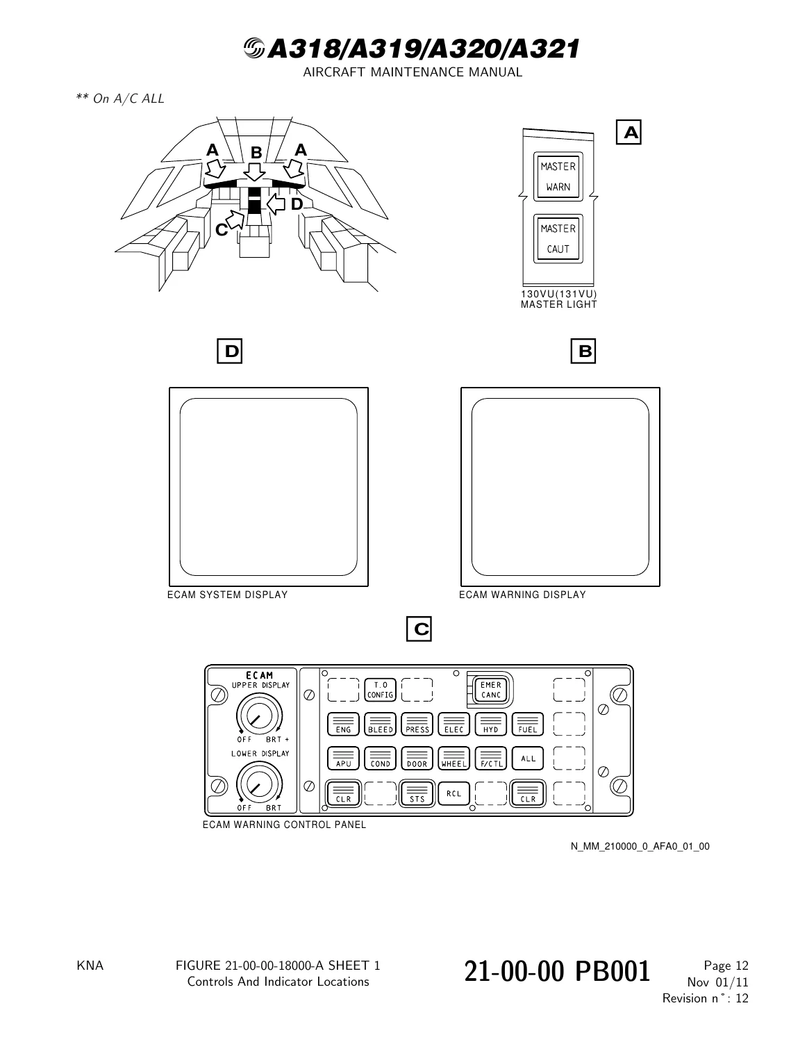
Figure 21-00-00-18000-A – Controls And Indicator Locationsp. 36
Figure 21-00-00-18100-A – Air Bleed Displayp. 37
Figure 21-00-00-18200-F – Air Cond. Displayp. 38
Figure 21-00-00-18300-A – Cabin Pressure Displayp. 39
Figure 21-00-00-18400-F – Cruise Display (CAB PRESS IN AUTO)p. 40
Figure 21-00-00-18500-F – Cruise Display (CAB PRESS IN MAN)p. 41
+21-00-00 PB 201 CONF 00 – AIR CONDITIONING – GENERAL – MAINTENANCE PRACTICESp. 42
+21-00-00-615-001-A – Decontamination of the Environmental Control System (ECS) when the Temperature is below 24 deg.C (APU)p. 42
Figure 21-00-00-991-00400-A – Blanking Caps – Specialp. 58
Figure 21-00-00-991-00100-G – ECS – Component Locationp. 59
+21-00-00-615-002-A – Decontamination of the Environmental Control System (ECS) when the Temperature is above 24 deg.C (APU)p. 60
Figure 21-00-00-991-00200-A – Temperature Simulating Device – Schematicp. 76
+21-00-00-615-003-A – Decontamination of the Environmental Control System (ECS) when the Temperature is below 24 deg.C (Engine/s)p. 77
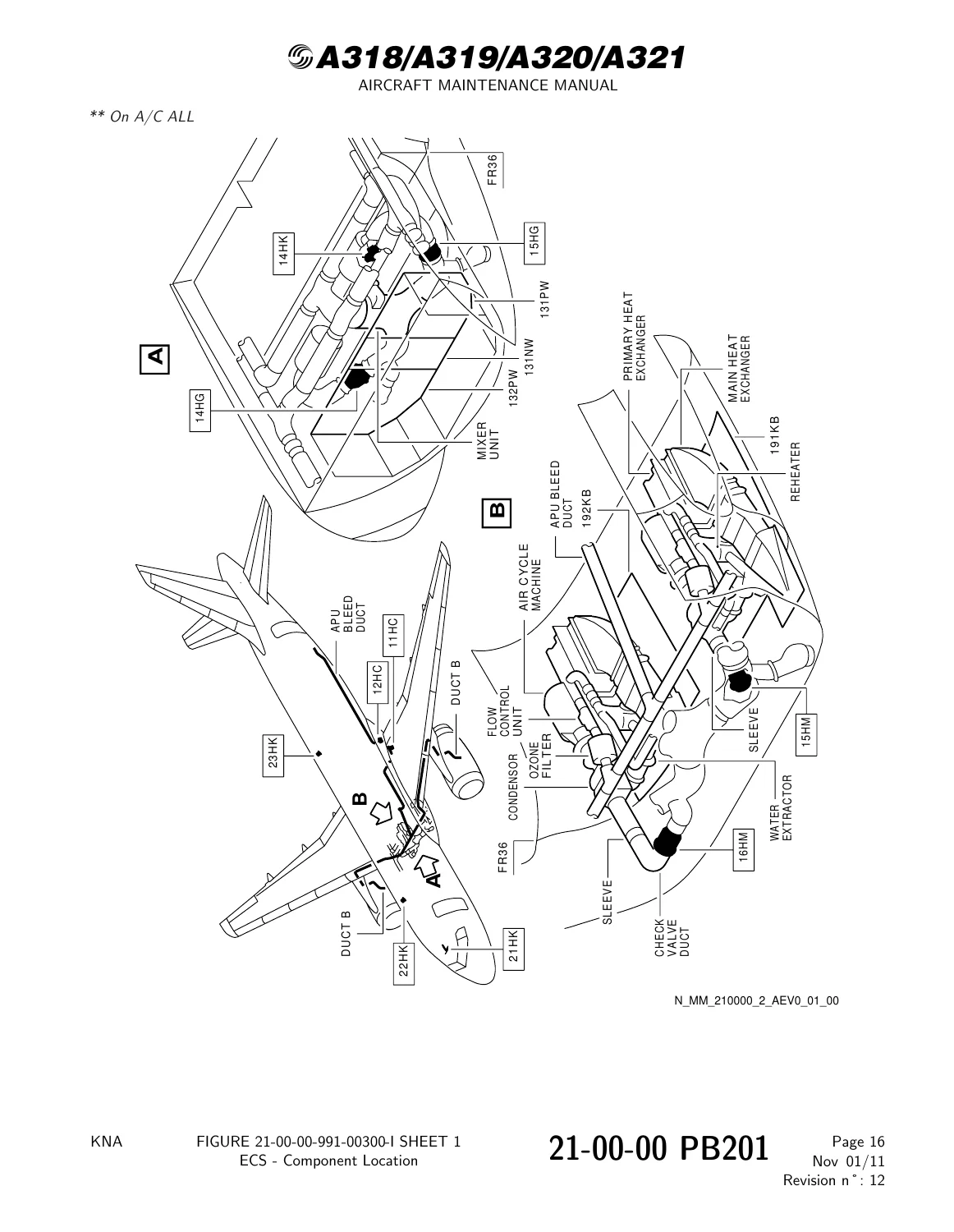
Figure 21-00-00-991-00300-I – ECS – Component Locationp. 92
21-00-00-615-004-A – Decontamination of the Environmental Control System (ECS) when the Temperature is above 24 deg.C (Engine/s)p. 93
+21-00-00-615-005-A – Decontamination of the Environmental Control System (ECS) after Dust or Volcanic Ash Contaminationp. 109
Figure 21-00-00-991-00500-B – ECS – Component Locationp. 113
21-00-00-100-001-A – Cleaning of Special Components in the Environmental Control System (ECS)p. 114
+21-20 – DISTRIBUTIONp. 117
+21-20-00 – DISTRIBUTIONp. 117
+21-20-00 PB 001 CONF 00 – DISTRIBUTION – DESCRIPTION AND OPERATIONp. 117
Generalp. 117
System Descriptionp. 118
+21-20-00 PB 201 CONF 00 – DISTRIBUTION – MAINTENANCE PRACTICESp. 119
+21-20-00-010-001-A – Removal of the Air-Conditioning Distribution Ductsp. 119
Figure 21-20-00-991-00100-A – Distribution Ducts Locationp. 122
Figure 21-20-00-991-00200-A – Examples of Distribution Duct Connectionsp. 123
Figure 21-20-00-991-00300-A – Examples of Distribution Duct Attachment Methodsp. 124
21-20-00-410-001-A – Installation of the Air-Conditioning Distribution Ductsp. 125
+21-20-00 PB 601 CONF 00 – DISTRIBUTION – INSPECTION/CHECKp. 130
+21-20-00-210-001-A – General Visual Inspection of the Riser Ducts in the Passenger Compartmentp. 130
Figure 21-20-00-991-00400-A – Riser Ducts – General Component Locationp. 134
21-20-00-210-002-A – General Visual Inspection of Lavatory and Galley Ventilation Ducting (Zones 210 to 260)p. 135
+21-21 – AIR DISTRIBUTION AND RECIRCULATIONp. 138
+21-21-00 – AIR DISTRIBUTION AND RECIRCULATIONp. 138
+21-21-00 PB 001 CONF 00 – AIR DISTRIBUTION AND RECIRCULATION – DESCRIPTION AND OPERATIONp. 138
Generalp. 138
Component Locationp. 139
System Descriptionp. 140
Power Supplyp. 142
Component Descriptionp. 143
Operation/Control and Indicatingp. 144
Figure 21-21-00-12900-A – Air Distribution and Recirculation – Component Locationp. 145
Figure 21-21-00-16000-A – Air Distribution – Passenger Cabinp. 147
Figure 21-21-00-16100-A – Air Distribution – Cockpitp. 148
Figure 21-21-00-16200-A – Air Distribution – Mixer Unitp. 149
Figure 21-21-00-17400-A – Cabin Fans – Schematicp. 150
Figure 21-21-00-19500-A – Recirculation Fanp. 151
Figure 21-21-00-21200-A – Controls and Indicationsp. 152
+21-21-00 PB 501 CONF 00 – AIR DISTRIBUTION AND RECIRCULATION – ADJUSTMENT/TESTp. 153
21-21-00-710-001-A – Operational Test of the Cabin Recirculation Fans 14HG and 15HG.p. 153
21-21-00-710-002-A – Operational Test of the Individual Air Outletp. 156
+21-21-41 – FILTER – RECIRCULATIONp. 158
+21-21-41 PB 301 CONF 00 – FILTER – RECIRCULATION – SERVICINGp. 158
+21-21-41-920-002-A – Scheduled Replacement of the Recirculation Filter 4012HMp. 158
Figure 21-21-41-991-00300-A – Recirculation Filterp. 159
+21-21-41 PB 401 CONF 00 – FILTER – RECIRCULATION – REMOVAL/INSTALLATIONp. 160
+21-21-41-000-001-A – Removal of the Recirculation Filter 4012HMp. 160
Figure 21-21-41-991-00100-A – Recirculation Filterp. 163
21-21-41-400-001-A – Installation of the Recirculation Filter 4012HMp. 164
+21-21-42 – CHECK VALVEp. 167
+21-21-42 PB 401 CONF 00 – CHECK VALVE – REMOVAL/INSTALLATIONp. 167
+21-21-42-000-001-A – Removal of the Recirculation Check Valve 4020HMp. 167
Figure 21-21-42-991-00100-A – Recirculation Check Valve 4020HM (4021HM).p. 169
21-21-42-400-001-A – Installation of the Recirculation Check Valve 4020HMp. 170
+21-21-43 – MIXER UNITp. 173
+21-21-43 PB 401 CONF 00 – MIXER UNIT – REMOVAL/INSTALLATIONp. 173
+21-21-43-000-001-A – Removal of the Mixer Unitp. 173
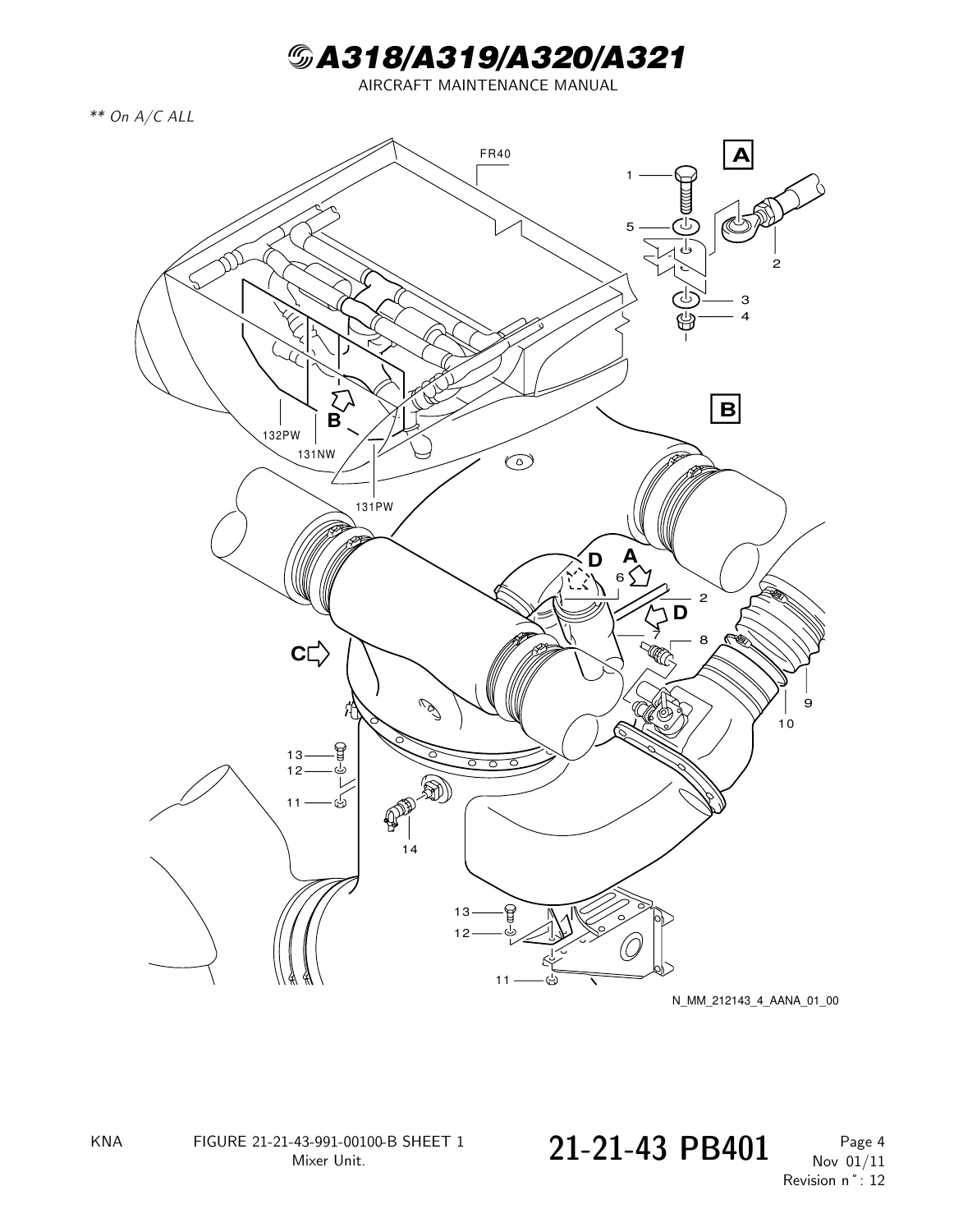
Figure 21-21-43-991-00100-B – Mixer Unit.p. 176
+21-21-43-000-002-A – Removal of the lower part of the Mixer Unitp. 179
Figure 21-21-43-991-00200-B – Lower part of the mixer unitp. 182
21-21-43-400-002-A – Installation of the Mixer Unitp. 183
21-21-43-400-003-A – Installation of the lower part of the Mixer Unitp. 189
+21-21-44 – AIR OUTLET – INDIVIDUAL, COCKPITp. 193
+21-21-44 PB 401 CONF 00 – AIR OUTLET – INDIVIDUAL, COCKPIT – REMOVAL/INSTALLATIONp. 193
+21-21-44-000-001-A – Removal of the CAPT (F/O) Individual Air-Outletp. 193
Figure 21-21-44-991-00100-B – CAPT (F/O) Individual Air-Outletp. 195
21-21-44-400-001-A – Installation of the CAPT (F/O) Individual Air-Outletp. 196
+21-21-44-000-002-A – Removal of the Third (Fourth) Occupant Individual Air-Outletp. 198
Figure 21-21-44-991-00200-B – Third (Fourth) Occupant Individual Air-Outletp. 199
21-21-44-400-002-A – Installation of the Third (Fourth) Occupant Individual Air-Outletp. 200
+21-21-49 – GRID – COCKPIT AIR SUPPLY DUCTp. 202
+21-21-49 PB 701 CONF 00 – GRID – COCKPIT AIR SUPPLY DUCT – CLEANING/PAINTINGp. 202
+21-21-49-100-001-A – Cleaning of the Cockpit Air-Supply Duct-Gridp. 202
Figure 21-21-49-991-00100-A – Cockpit Air Supply Duct Gridp. 204
+21-21-51 – FAN – RECIRCULATIONp. 205
+21-21-51 PB 401 CONF 00 – FAN – RECIRCULATION – REMOVAL/INSTALLATIONp. 205
+21-21-51-000-001-A – Removal of the Cabin Recirculation Fans 15HG and 14HGp. 205
Figure 21-21-51-991-00100-A – Cabin Recirculation Fan 15HG (14HG)p. 208
21-21-51-400-001-A – Installation of the Cabin Recirculation Fans 15HG and 14HGp. 209
+21-23 – LAVATORY/GALLEY VENTILATIONp. 213
+21-23-00 – LAVATORY/GALLEY VENTILATIONp. 213
+21-23-00 PB 001 CONF 00 – LAVATORY/GALLEY VENTILATION – DESCRIPTION AND OPERATIONp. 213
Generalp. 213
Component Locationp. 214
System Descriptionp. 215
Power Supplyp. 216
Interfacep. 217
Component Descriptionp. 218
Operation/Control and Indicatingp. 219
Figure 21-23-00-12600-B – Lavatory and Galley Ventilation Systemp. 220
Figure 21-23-00-15800-A – Lavatory and Galley Ventilation System – Electrical Schematicp. 221
Figure 21-23-00-18400-A – Extraction Fan (1HU)p. 222
+21-23-00 PB 301 CONF 00 – LAVATORY/GALLEY VENTILATION – SERVICINGp. 223
+21-23-00-600-001-A – Replacement of the Lavatory Air-Extraction Filterp. 223
Figure 21-23-00-991-00200-A – Lavatory Air-Extraction Filterp. 225
+21-23-00 PB 401 CONF 00 – LAVATORY/GALLEY VENTILATION – DEACTIVATION/REACTIVATIONp. 226
21-23-00-440-001-A – Reactivation of the Lavatory/Galley Extraction Fan 1HUp. 226
+21-23-00 PB 501 CONF 00 – LAVATORY/GALLEY VENTILATION – ADJUSTMENT/TESTp. 228
+21-23-00-720-001-A – Functional Test of the Galley/Lavatory Air Extraction Ductp. 228
Figure 21-23-00-991-00100-A – Pressure Measurement Point – Locationsp. 231
21-23-00-720-002-A – Functional Test of an Air Extraction Pointp. 232
+21-23-51 – FAN-EXTRACTp. 233
+21-23-51 PB 401 CONF 00 – FAN-EXTRACT – REMOVAL/INSTALLATIONp. 233
+21-23-51-000-001-A – Removal of the Lavatory and Galley Extract Fanp. 233
Figure 21-23-51-991-00100-B – Lavatory and Galley Extract Fanp. 235
21-23-51-400-001-A – Installation of the Lavatory and Galley Extract Fanp. 236
+21-24 – INDIVIDUAL AIR DISTRIBUTIONp. 239
+21-24-00 – INDIVIDUAL AIR DISTRIBUTIONp. 239
+21-24-00 PB 001 CONF 00 – INDIVIDUAL AIR DISTRIBUTION – DESCRIPTION AND OPERATIONp. 239
Generalp. 239
Figure 21-24-00-11300-A – Individual Air Ventilationp. 240
+21-24-00 PB 801 CONF 00 – INDIVIDUAL AIR DISTRIBUTION – REPAIRSp. 241
+21-24-00-340-001-A – Repair of the Individual Air Outletp. 241
Figure 21-24-00-991-00100-A – Air Outlet Repairp. 244
+21-24-19 – AIR OUTLET – INDIVIDUALp. 245
+21-24-19 PB 401 CONF 00 – AIR OUTLET – INDIVIDUAL – REMOVAL/INSTALLATIONp. 245
+21-24-19-000-001-A – Removal of the Individual Air Outlet 4150 HMp. 245
Figure 21-24-19-991-00100-A – Individual Air Outlets.p. 247
21-24-19-400-001-A – Installation of the Individual Air outlet 4150 HMp. 248
+21-26 – AVIONICS EQUIPMENT VENTILATIONp. 250
+21-26-00 – AVIONICS EQUIPMENT VENTILATIONp. 250
+21-26-00 PB 001 CONF 00 – AVIONICS EQUIPMENT VENTILATION – DESCRIPTION AND OPERATIONp. 250
Generalp. 250
Component Locationp. 251
System Descriptionp. 252
Power Supplyp. 253
Interfacesp. 254
Component Descriptionp. 255
Operation/Control and Indicatingp. 258
BITE Testp. 261
Figure 21-26-00-11200-M – Avionics Equipment Ventilation – General Arrangementp. 262
Figure 21-26-00-12400-K – Avionics Equipment Ventilation – Component Locationp. 263
Figure 21-26-00-12500-C – Avionics Equipment Ventilation – Component Locationp. 264
Figure 21-26-00-18400-D – Avionics Equipment Ventilation Schematic (Sheet 1/3)p. 265
Figure 21-26-00-18500-D – Avionics Equipment Ventilation Schematic (Sheet 2/3)p. 266
Figure 21-26-00-19900-B – Avionics Equipment Ventilation Computer (AEVC) – Locationp. 267
Figure 21-26-00-20300-B – Blower/Extract Fansp. 268
Figure 21-26-00-21000-B – Skin Air Inlet Valvep. 269
Figure 21-26-00-21400-B – Skin Air Outlet Valvep. 270
Figure 21-26-00-21800-A – Skin Exchanger Inlet Bypass Valve/Skin Exchanger Isolation Valve/ Skin Exchanger Outlet Bypass Valvep. 271
Figure 21-26-00-22800-A – Conditioned Air Inlet Valvep. 272
Figure 21-26-00-23200-A – Check Valvep. 273
Figure 21-26-00-23600-A – Check Valvep. 274
Figure 21-26-00-24000-B – Filter Assemblyp. 275
Figure 21-26-00-25000-A – Fans Speed Controllerp. 276
Figure 21-26-00-25100-B – Duct Temperature Sensorsp. 277
Figure 21-26-00-25500-A – Pressure Switches 17HQ/19HQ/30HQp. 278
Figure 21-26-00-26500-B – Skin Temperature Sensorp. 279
Figure 21-26-00-27900-C – Avionics Equipment Ventilation – Operation Tablep. 280
Figure 21-26-00-28000-A – Avionics Equipment Ventilation Schematic (Sheet 3/3)p. 281
Figure 21-26-00-28900-A – VENTILATION Panelp. 282
Figure 21-26-00-30100-A – TEST Procedure from the CFDSp. 283
Figure 21-26-00-30200-A – LAST LEG REPORT from the CFDSp. 284
Figure 21-26-00-30300-A – CLASS 3 FAULTS from the CFDSp. 285
+21-26-00 PB 201 CONF 00 – AVIONICS EQUIPMENT VENTILATION – MAINTENANCE PRACTICESp. 286
+21-26-00-860-001-A – Configuration of the Avionics Compartment Ventilation Systemp. 286
Figure 21-26-00-991-00700-A – Deactivation of the Valvesp. 290
21-26-00-860-001-A-01 – Configuration of the Avionics Compartment Ventilation Systemp. 294
+21-26-00-860-002-A – Ground Operations in Heavy Rainp. 296
Figure 21-26-00-991-01700-A – Location of Panels 22VU and 30VUp. 299
+21-26-00 PB 401 CONF 00 – AVIONICS EQUIPMENT VENTILATION – DEACTIVATION/REACTIVATIONp. 300
+21-26-00-040-001-A – Deactivation of the Skin Exchanger Inlet Bypass Valvep. 300
Figure 21-26-00-991-01200-A – Skin Exchanger Inlet Bypass Valvep. 303
21-26-00-440-001-A – Reactivation of the Skin Exchanger Inlet Bypass valvep. 304
+21-26-00-040-002-A – Deactivation of the Skin Air Outlet Valve in the Closed Position with the Auxiliary Flap in the Open Positionp. 306
Figure 21-26-00-991-00800-B – Skin-Air Outlet Valvep. 311
Figure 21-26-00-991-01000-A – Skin Exchanger Isolation Valvep. 312
Figure 21-26-00-991-01800-A – ECAM Display after Deactivation of the Skin Air Outlet Valvep. 313
21-26-00-440-002-A – Reactivation of the Skin Air Outlet Valve from the Closed Positionp. 314
+21-26-00-040-003-A – Deactivation of the Conditioned-Air Inlet Valvep. 317
Figure 21-26-00-991-00900-A – Air Conditioned Inlet Valvep. 320
21-26-00-440-003-A – Reactivation of the Conditioned-Air Inlet Valvep. 321
+21-26-00-040-004-A – Deactivation of the Skin Air Inlet Valvep. 323
Figure 21-26-00-991-00500-B – Skin Air-Inlet Valvep. 326
21-26-00-040-014-A – Skin Air-Inlet Valve Inoperative – Do the Deactivation of the Conditioned-Air Inlet Valvep. 327
21-26-00-440-004-A – Reactivation of the Skin Air Inlet Valvep. 330
21-26-00-040-005-A – Avionics Equipment Ventilation Computer Inoperative (AEVC) – Check of the Ventilation Systemp. 333
21-26-00-440-005-A – Reactivation of the Avionics Equipment Ventilation Computer (AEVC)p. 336
+21-26-00-040-006-A – Blower Fan Inoperative – Check that the Air Conditioned Inlet Valve is Openp. 338
Figure 21-26-00-991-01100-A – Conditioned Air Inlet Valvep. 340
21-26-00-440-006-A – Reactivation of the Blower Fanp. 341
21-26-00-040-013-A – Deactivation of the Conditioned-Air Inlet Valve when the Blower Fan is Inoperativep. 342
21-26-00-440-013-A – Reactivation of the Conditioned-Air Inlet Valve and of the Blower Fanp. 345
21-26-00-040-007-A – Extract Fan Inoperative – Check of Conditioned-Air Inlet Valve Openp. 347
21-26-00-040-015-A – Extract Fan Inoperative – Do the Deactivation of the Conditioned-Air Inlet Valvep. 349
21-26-00-440-015-A – Extract Fan Inoperative – Do the Reactivation of the Conditioned-Air Inlet Valvep. 352
21-26-00-440-007-A – Reactivation of the Extract Fanp. 354
21-26-00-040-008-A – Skin-Exchanger Isolation Valve Inoperative – Check of the Open Position of the Valvep. 356
21-26-00-040-016-A – Deactivation of the Skin-Exchanger Isolation Valvep. 358
21-26-00-440-008-A – Reactivation of the Skin-Exchanger Isolation Valvep. 361
21-26-00-040-009-A – Deactivation of the Avionics Ventilation Filterp. 363
21-26-00-040-017-A – Avionics Ventilation Filter Inoperative – Do the Deactivation of the Conditioned-Air Inlet Valvep. 365
21-26-00-440-009-A – Reactivation of the Avionics Ventilation Filterp. 368
21-26-00-040-010-A – Blower Fault Warning – Check of the Blower Fan and AVNCS SYS FAULT Warningp. 369
21-26-00-440-010-A – Reactivation of the Blower Fault Warningp. 371
21-26-00-040-011-A – Extract Fault Warning – Check of the Extract Fan and AVNCS SYS FAULT Warningp. 372
21-26-00-440-011-A – Reactivation of the Extract Fault Warningp. 374
21-26-00-040-012-A – ADIRU/AVNCS VENT Caution Light Inoperativep. 375
21-26-00-440-012-A – Reactivation of the ADIRU/AVNCS VENT Caution Lightp. 377
+21-26-00 PB 501 CONF 00 – AVIONICS EQUIPMENT VENTILATION – ADJUSTMENT/TESTp. 378
21-26-00-710-001-A – Operational Check of the Avionics Equipment Ventilation-System via MCDUp. 378
21-26-00-710-001-A-01 – Operational Check of the Avionics Equipment Ventilation (without the CFDS)p. 382
+21-26-00-710-013-A – Operational Check of Fan High Speed Modep. 385
Figure 21-26-00-991-01500-A – Testing Tool Installationp. 388
21-26-00-710-002-A – Operational Check of Override Function (BLOWER and EXTRACT)p. 389
21-26-00-710-003-A – Operational Check of Smoke Configuration Control Circuitp. 392
21-26-00-710-004-A – Operational Check of Ditching Configuration Control Circuitp. 395
+21-26-00-710-008-A – Operational Test to Read the CFDS for CLASS 3 Faults of the AEVCp. 398
Figure 21-26-00-991-01300-A – CLASS 3 FAULTS from the CFDSp. 400
+21-26-00-710-009-A – Operational Test to Read the CFDS for LAST LEG REPORT of the AEVCp. 401
Figure 21-26-00-991-01400-A – LAST LEG REPORT from the CFDSp. 403
+21-26-11 – PRESSURE SWITCHES – BLOWER AND EXTRACT FANp. 404
+21-26-11 PB 401 CONF 00 – PRESSURE SWITCHES – BLOWER AND EXTRACT FAN – REMOVAL/INSTALLATIONp. 404
+21-26-11-000-001-A – Removal of the Blower and Extract Fan Pressure Switchesp. 404
Figure 21-26-11-991-00100-A – Blower Fan Pressure Switchesp. 406
Figure 21-26-11-991-00200-A – Extract Fan Pressure Switchp. 407
21-26-11-400-001-A – Installation of the Blower and Extract Fan Pressure Switchesp. 408
+21-26-11 PB 501 CONF 00 – PRESSURE SWITCHES – BLOWER AND EXTRACT FAN – ADJUSTMENT/TESTp. 412
21-26-11-710-001-A – Operational Test of the Extract-Fan Pressure Switch (without the CFDS)p. 412
+21-26-12 – SENSOR – DUCT TEMPERATUREp. 414
+21-26-12 PB 401 CONF 00 – SENSOR – DUCT TEMPERATURE – REMOVAL/INSTALLATIONp. 414
+21-26-12-000-001-B – Removal of the Avionics Ventilation Duct Temperature Sensorsp. 414
Figure 21-26-12-991-00200-A – Duct Temperature Sensorsp. 416
21-26-12-400-001-B – Installation of the Avionics Ventilation Duct Temperature Sensorsp. 417
+21-26-13 – SENSOR – SKIN TEMPERATUREp. 420
+21-26-13 PB 401 CONF 00 – SENSOR – SKIN TEMPERATURE – REMOVAL/INSTALLATIONp. 420
+21-26-13-000-001-A – Removal of the Avionics Ventilation Skin Temperature Sensorp. 420
Figure 21-26-13-991-00100-B – Skin Temperature Sensorp. 422
21-26-13-400-001-A – Installation of the Avionics Ventilation Skin Temperature Sensorp. 423
+21-26-13 PB 501 CONF 00 – SENSOR – SKIN TEMPERATURE – ADJUSTMENT/TESTp. 425
21-26-13-710-001-A – Operational Test of the Skin Temperature Sensor (without the CFDS)p. 425
+21-26-34 – COMPUTER – AVIONICS EQUIPMENT VENTILATION (AEVC)p. 428
+21-26-34 PB 401 CONF 00 – COMPUTER – AVIONICS EQUIPMENT VENTILATION (AEVC) – REMOVAL/INSTALLATIONp. 428
+21-26-34-000-001-A – Removal of the Avionics Equipment Ventilation Computer (AEVC) (10HQ)p. 428
Figure 21-26-34-991-00100-B – Avionics Equipment Ventilation Computer (AEVC)p. 430
21-26-34-400-001-A – Installation of the Avionics Equipment Ventilation Computer (AEVC) (10HQ)p. 431
+21-26-35 – CONTROLLER – AVIONICS VENTILATION FANS SPEEDp. 434
+21-26-35 PB 401 CONF 00 – CONTROLLER – AVIONICS VENTILATION FANS SPEED – REMOVAL/INSTALLATIONp. 434
+21-26-35-000-001-A – Removal of the Avionics Ventilation Fans Speed Controllerp. 434
Figure 21-26-35-991-00100-A – Avionics Ventilation Fans Speed Controllerp. 436
21-26-35-400-001-A – Installation of the Avionics Ventilation Fans Speed Controllerp. 437
+21-26-41 – CHECK VALVEp. 439
+21-26-41 PB 401 CONF 00 – CHECK VALVE – REMOVAL/INSTALLATIONp. 439
+21-26-41-000-001-A – Removal of the Check Valvep. 439
Figure 21-26-41-991-00100-C – Check Valvep. 441
21-26-41-400-001-A – Installation of the Check Valvep. 442
+21-26-41-000-002-A – Removal of the Air Extraction Ductp. 445
Figure 21-26-41-991-00200-B – Air Extraction Ductp. 447
21-26-41-400-002-A – Installation of the Air Extraction Ductp. 448
+21-26-41 PB 601 CONF 00 – CHECK VALVE – INSPECTION/CHECKp. 451
21-26-41-210-001-A – Detailed Inspection of Check Valve Flappers for Condition and Operationp. 451
+21-26-42 – AVIONICS EQUIPMENT VENTILATION DUCTSp. 453
+21-26-42 PB 401 CONF 00 – AVIONICS EQUIPMENT VENTILATION DUCTS – REMOVAL/INSTALLATIONp. 453
+21-26-42-000-001-A – Removal of the Avionics Equipment Ventilation Ductp. 453
Figure 21-26-42-991-00100-A – Avionics Equipment Ventilation Ductp. 455
21-26-42-400-001-A – Installation of the Avionics Equipment Ventilation Ductp. 456
+21-26-42-000-002-A – Removal of the Avionics Equipment Blowing and Extraction Ductsp. 458
Figure 21-26-42-991-00900-A – Avionics Equipment Blowing-Ductp. 460
Figure 21-26-42-991-01000-A – Avionics Equipment Extraction-Ductsp. 461
21-26-42-400-002-A – Installation of the Avionics Equipment Blowing and Extraction Ductsp. 462
+21-26-42 PB 601 CONF 00 – AVIONICS EQUIPMENT VENTILATION DUCTS – INSPECTION/CHECKp. 465
+21-26-42-200-001-A – Inspection/Check of the Skin Heat Exchanger (Inlet Duct)p. 465
Figure 21-26-42-991-00200-A – Inlet Ductp. 469
+21-26-42-200-002-A – Inspection/Check of the Skin Heat Exchanger (Outlet Duct)p. 470
Figure 21-26-42-991-00300-A – Outlet Ductp. 473
21-26-42-200-003-A – Detailed Inspection of Skin Heat Exchanger Drain Hose Connection Areap. 474
+21-26-42-210-002-A – Detailed Inspection of Elbow Drain Hose Connection Area Downstream of Blower Fanp. 475
Figure 21-26-42-991-00500-A – Drain Hole/Hose and Syphon and Filter Assemblyp. 478
+21-26-43 – FILTER – DEMISTERp. 479
+21-26-43 PB 401 CONF 02 – FILTER ASSY – AVIONICS VENTILATION – REMOVAL/INSTALLATIONp. 479
+21-26-43-000-003-A – Removal of the Filter Assemblyp. 479
Figure 21-26-43-991-01000-A – Filter Assemblyp. 481
21-26-43-400-003-A – Installation of the Filter Assemblyp. 482
+21-26-43-920-001-A – Replacement of the Filter Cartridgep. 485
Figure 21-26-43-991-01800-A – Filter Cartridgep. 488
+21-26-43 PB 501 CONF 02 – FILTER ASSY – AVIONICS VENTILATION – ADJUSTMENT/TESTp. 489
+21-26-43-710-001-A – Operational Check of NRV for Free Movement and Confirm the Bowl is Cleanp. 489
Figure 21-26-43-991-01600-A – Check Valve of the Avionics Ventillation Water / Dust Separationp. 492
+21-26-43 PB 701 CONF 02 – FILTER ASSY – AVIONICS VENTILATION – CLEANING/PAINTINGp. 493
+21-26-43-100-001-A – Inspection of the Syphon Assembly (Strainer) for Cleanlinessp. 493
Figure 21-26-43-991-01700-A – Syphon Assemblyp. 496
+21-26-45 – HEAT EXCHANGER – SKINp. 497
+21-26-45 PB 401 CONF 00 – HEAT EXCHANGER – SKIN – REMOVAL/INSTALLATIONp. 497
+21-26-45-000-001-A – Removal of the Skin Heat Exchangerp. 497
Figure 21-26-45-991-00100-A – Skin Heat Exchangerp. 499
21-26-45-400-001-A – Installation of the Skin Heat Exchangerp. 500
+21-26-51 – FANS – EXTRACT AND BLOWERp. 502
+21-26-51 PB 401 CONF 00 – FANS – EXTRACT AND BLOWER – REMOVAL/INSTALLATIONp. 502
+21-26-51-000-001-A – Removal of the Extract and Blower Fansp. 502
Figure 21-26-51-991-00100-A – Extract Fanp. 504
Figure 21-26-51-991-00200-A – Blower Fanp. 505
21-26-51-400-001-A – Installation of the Extract and Blower Fansp. 506
+21-26-51 PB 501 CONF 00 – FANS – EXTRACT AND BLOWER – ADJUSTMENT/TESTp. 509
21-26-51-710-001-A – Operational Test of the Extract and Blower Fans (without the CFDS)p. 509
+21-26-52 – VALVE – SKIN AIR INLETp. 511
+21-26-52 PB 401 CONF 00 – VALVE – SKIN AIR INLET – REMOVAL/INSTALLATIONp. 511
+21-26-52-000-001-A – Removal of the Avionics Ventilation Skin Air Inlet Valvep. 511
Figure 21-26-52-991-00100-B – Skin Air Inlet Valvep. 513
21-26-52-400-001-A – Installation of the Avionics Ventilation Skin Air Inlet Valvep. 514
+21-26-53 – VALVE – SKIN AIR OUTLETp. 517
+21-26-53 PB 401 CONF 00 – VALVE – SKIN AIR OUTLET – REMOVAL/INSTALLATIONp. 517
+21-26-53-000-002-A – Removal of the Skin Air Outlet-Valvep. 517
Figure 21-26-53-991-00100-A – Skin Air Outlet-Valvep. 519
21-26-53-400-001-A – Installation of the Skin Air Outlet-Valvep. 520
+21-26-54 – VALVE – CONDITIONED AIR INLETp. 523
+21-26-54 PB 401 CONF 00 – VALVE – CONDITIONED AIR INLET – REMOVAL/INSTALLATIONp. 523
+21-26-54-000-001-A – Removal of the Conditioned Air Inlet Valvep. 523
Figure 21-26-54-991-00100-A – Conditioned Air Inlet Valvep. 525
21-26-54-400-001-A – Installation of the Conditioned Air Inlet Valvep. 526
+21-26-55 – VALVES – SKIN EXCHANGERp. 529
+21-26-55 PB 401 CONF 00 – VALVES – SKIN EXCHANGER – REMOVAL/INSTALLATIONp. 529
+21-26-55-000-001-B – Removal of the Avionics Ventilation Skin Exchanger Inlet Bypass Valvep. 529
Figure 21-26-55-991-00200-A – Skin Exchanger Inlet Bypass Valvep. 531
21-26-55-400-001-B – Installation of the Avionics Ventilation Skin Exchanger Inlet Bypass Valvep. 532
+21-26-55-000-002-A – Removal of the Avionics Ventilation Skin Exchanger Isolation Valvep. 535
Figure 21-26-55-991-00300-A – Skin Exchanger Isolation Valvep. 537
21-26-55-400-002-A – Installation of the Avionics Ventilation Skin Exchanger Isolation Valvep. 538
+21-26-55-000-003-A – Removal of the Avionics Ventilation Skin Exchanger Outlet Bypass Valvep. 541
Figure 21-26-55-991-00400-A – Skin Exchanger Outlet Bypass Valvep. 543
21-26-55-400-003-A – Installation of the Avionics Ventilation Skin Exchanger Outlet Bypass Valvep. 544
+21-26-55 PB 501 CONF 00 – VALVES – SKIN EXCHANGER – ADJUSTMENT/TESTp. 547
21-26-55-710-001-A – Operational Test of the Skin-Exchanger Outlet Bypass-Valve without the Centralized Fault Display System (CFDS)p. 547
+21-26-56 – CHECK VALVE – AIR INLETp. 550
+21-26-56 PB 401 CONF 00 – CHECK VALVE – AIR INLET – REMOVAL/INSTALLATIONp. 550
+21-26-56-000-001-A – Removal of the Air Inlet Check Valvep. 550
Figure 21-26-56-991-00100-A – Air Inlet Check Valvep. 552
21-26-56-400-001-A – Installation of the Air Inlet Check Valvep. 553
+21-26-56 PB 501 CONF 00 – CHECK VALVE – AIR INLET – ADJUSTMENT/TESTp. 556
+21-26-56-280-002-A – Operational Check of Air Inlet Check Valvep. 556
Figure 21-26-56-991-00300-B – Air Inlet Check Valvep. 559
+21-28 – CARGO COMPARTMENT VENTILATIONp. 560
+21-28-00 – CARGO COMPARTMENT VENTILATIONp. 560
+21-28-00 PB 001 CONF 00 – CARGO COMPARTMENT VENTILATION – DESCRIPTION AND OPERATIONp. 560
Generalp. 560
Component Locationp. 561
System Descriptionp. 562
Power Supplyp. 563
Component Descriptionp. 564
Operation/Control and Indicatingp. 565
Figure 21-28-00-12400-E – AFT Cargo-Compartment Ventilation-System – Component Locationp. 566
Figure 21-28-00-12500-H – AFT Cargo-Compartment Ventilation-System – Component Locationp. 567
Figure 21-28-00-13900-G – AFT Cargo-Compartment Ventilation – Schematicp. 568
Figure 21-28-00-15200-B – AFT Cargo-Compartment Ventilation – Electrical Schematicp. 569
Figure 21-28-00-18300-B – Isolation Valvep. 570
Figure 21-28-00-18400-B – Extraction Fanp. 571
+21-28-00 PB 401 CONF 00 – CARGO COMPARTMENT VENTILATION – DEACTIVATION/REACTIVATIONp. 572
+21-28-00-040-002-A – Deactivation of the Aft Cargo-Compartment Ventilation Isolation-Valves 33HN, 34HNp. 572
Figure 21-28-00-991-00200-A – Cargo-Compartment Ventilation Isolation-Valves – Component Locationp. 575
21-28-00-440-002-A – Reactivation of the AFT Cargo-Compartment Ventilation Isolation-Valves 33HN, 34HNp. 576
+21-28-00 PB 501 CONF 00 – CARGO COMPARTMENT VENTILATION – ADJUSTMENT/TESTp. 579
21-28-00-720-004-A – Functional Test of the AFT Cargo-Compartment Ventilation-Systemp. 579
21-28-00-710-006-A – Operational Test of the AFT Cargo-Compartment Ventilation-Systemp. 583
+21-28-34 – CONTROLLER – VENTILATIONp. 587
+21-28-34 PB 401 CONF 00 – CONTROLLER – VENTILATION – REMOVAL/INSTALLATIONp. 587
+21-28-34-000-001-A – Removal of the Ventilation Controllerp. 587
Figure 21-28-34-991-00100-B – Ventilation Controllerp. 589
21-28-34-400-001-A – Installation of the Ventilation Controllerp. 590
+21-28-52 – VALVE – ISOLATION, AFT CARGO COMPARTMENTp. 592
+21-28-52 PB 401 CONF 00 – VALVE – ISOLATION, AFT CARGO COMPARTMENT – REMOVAL/INSTALLATIONp. 592
+21-28-52-000-001-A – Removal of the AFT Cargo-Compartment Ventilation Isolation-Valvesp. 592
Figure 21-28-52-991-00100-A – AFT Cargo Isolation Valvesp. 595
21-28-52-400-001-A – Installation of the AFT Cargo-Compartment Ventilation Isolation-Valvesp. 597
+21-28-54 – FAN – EXTRACTION, AFT CARGO COMPARTMENTp. 601
+21-28-54 PB 401 CONF 00 – FAN – EXTRACTION, AFT CARGO COMPARTMENT – REMOVAL/INSTALLATIONp. 601
+21-28-54-000-001-A – Removal of the Aft Cargo-Compartment Ventilation Extraction-Fanp. 601
Figure 21-28-54-991-00100-A – Aft Cargo-Compartment Ventilation Extraction-Fanp. 603
21-28-54-400-001-A – Installation of the Aft Cargo-Compartment Ventilation Extraction-Fanp. 604
+21-30 – PRESSURIZATION CONTROLp. 607
+21-30-00 – PRESSURIZATION CONTROLp. 607
+21-30-00 PB 001 CONF 00 – PRESSURIZATION CONTROL – DESCRIPTION AND OPERATIONp. 607
+21-31 – PRESSURE CONTROL AND MONITORINGp. 608
+21-31-00 – PRESSURE CONTROL AND MONITORINGp. 608
+21-31-00 PB 001 CONF 00 – PRESSURE CONTROL AND MONITORING – DESCRIPTION AND OPERATIONp. 608
Generalp. 608
Component Locationp. 609
System Descriptionp. 610
Power Supplyp. 613
Interfacep. 614
Component Descriptionp. 620
Operation/Control and Indicatingp. 624
BITE Testp. 629
Figure 21-31-00-12400-C – Pressure Control System – Component Locationp. 641
Figure 21-31-00-14600-A – Mode Logic Switchingp. 644
Figure 21-31-00-14700-D – Mode Logic Tablep. 645
Figure 21-31-00-14800-A – System Operation Logicp. 646
Figure 21-31-00-14900-A – Climb Pressure Schedulep. 647
Figure 21-31-00-15000-A – Climbp. 648
Figure 21-31-00-16200-C – Pressure Control System – Schematicp. 649
Figure 21-31-00-19900-B – CPC Signal Interfacep. 652
Figure 21-31-00-20000-A – CPC Interface Inputsp. 653
Figure 21-31-00-20100-A – CPC Interface Outputsp. 654
Figure 21-31-00-23200-A – CPC – Block Diagramp. 655
Figure 21-31-00-23400-A – Outflow Valvep. 656
Figure 21-31-00-23500-A – Outflow Valvep. 657
Figure 21-31-00-23600-A – Actuator Geartrain – Schematicp. 658
Figure 21-31-00-23700-B – Safety Valvep. 659
Figure 21-31-00-23800-A – Cabin Pressure/Altitude Envelopep. 660
Figure 21-31-00-27400-B – Pressure Control System – Block Diagramp. 661
Figure 21-31-00-27500-B – CABIN PRESS – Panel 25VUp. 662
Figure 21-31-00-31000-A – MCDU – LAST/PREVIOUS LEG REPORT and LRU IDENTIFICATIONp. 663
Figure 21-31-00-31100-B – MCDU – TEST/CALIBRATIONp. 664
Figure 21-31-00-31200-A – MCDU – CLASS 3 FAULTSp. 666
+21-31-00 PB 301 CONF 00 – PRESSURE CONTROL AND MONITORING – SERVICINGp. 667
21-31-00-600-001-A – Replace Safety Valve for Restorationp. 667
+21-31-00 PB 401 CONF 00 – PRESSURE CONTROL AND MONITORING – DEACTIVATION/REACTIVATIONp. 668
21-31-00-040-001-A – Verification Test (Safety Valves and Outflow Valve)p. 668
21-31-00-040-002-A – Verification Test of the Automatic Cabin-Pressure Control-Systemsp. 673
+21-31-00-040-004-A – Verification Test of the Safety Valves (6HL,7HL) (Position Indication on ECAM CAB PRESS Page)p. 676
Figure 21-31-00-991-00500-A – Safety Valves (6HL,7HL) – Visual Inspectionp. 677
21-31-00-040-005-A – Verification Test of the Safety Valves (6HL,7HL) (OPEN Caution on ECAM)p. 678
21-31-00-040-006-A – Deactivation of the CPC2p. 679
21-31-00-440-003-A – Reactivation of the CPC2p. 681
21-31-00-040-007-A – Deactivation of the CPC1p. 682
21-31-00-440-004-A – Reactivation of the CPC1p. 684
+21-31-00 PB 501 CONF 00 – PRESSURE CONTROL AND MONITORING – ADJUSTMENT/TESTp. 685
21-31-00-710-002-A – Operational Test of the Pressure Control and Monitoringp. 685
21-31-00-710-003-A – Operational Test of Manual Mode Selection and Manual Mode Pressure Control and Functional Test of Manual Mode Cabin Altitude/Outflow Valve Position Indicationp. 688
21-31-00-710-004-A – Operational Test of the Outflow Valve Closing in Ditching Configurationp. 691
21-31-00-710-005-A – Operational Test of Outflow Valve Partial Opening by Emergency Ram Air Switchp. 694
21-31-00-710-006-A – Operational Test of Safety Valve Position Indicationp. 697
+21-31-00-720-001-A – Functional Test of the Positive and Negative Delta P Protection of the Safety Valvesp. 700
Figure 21-31-00-991-00100-A – Safety Valve – Differential Pressure Testp. 706
+21-31-00-760-001-A – Resistance Check of the Return Ground Connections – Cabin Pressure Controller (CPC) 1 (11HL) and 2 (12HL) and the Electronic Modules 10HL-1 and 10HL-2p. 708
Figure 21-31-00-991-00400-B – Return Ground Connections – Earthing Pointsp. 714
+21-31-00 PB 701 CONF 00 – PRESSURE CONTROL AND MONITORING – CLEANING/PAINTINGp. 716
+21-31-00-100-001-A – Cleaning of the Moveable Seals of the Outflow-Valvep. 716
Figure 21-31-00-991-00600-A – Outflow-Valve Moveable Seals – Component Locationp. 719
+21-31-34 – CONTROLLER – CABIN PRESSUREp. 720
+21-31-34 PB 401 CONF 00 – CONTROLLER – CABIN PRESSURE – REMOVAL/INSTALLATIONp. 720
+21-31-34-000-001-A – Removal of the Cabin Pressure Controllerp. 720
Figure 21-31-34-991-00100-B – Cabin Pressure Controllerp. 722
Figure 21-31-34-991-00100-C – Cabin Pressure Controllerp. 723
21-31-34-400-001-A – Installation of the Cabin Pressure Controllerp. 724
+21-31-35 – CONTROL UNIT – RESIDUAL PRESSUREp. 727
+21-31-35 PB 401 CONF 00 – CONTROL UNIT – RESIDUAL PRESSURE – REMOVAL/INSTALLATIONp. 727
+21-31-35-000-001-A – Removal of the Residual Pressure Control Unit (9HL)p. 727
Figure 21-31-35-991-00100-A – Residual Pressure Control Unitp. 729
21-31-35-400-001-A – Installation of the Residual Pressure Control Unit (9HL)p. 730
+21-31-51 – VALVE – OUTFLOWp. 732
+21-31-51 PB 401 CONF 00 – VALVE – OUTFLOW – REMOVAL/INSTALLATIONp. 732
+21-31-51-000-001-A – Removal of the Outflow Valve 10HL (From Inside)p. 732
Figure 21-31-51-991-00100-D – Outflow Valve 10HLp. 736
21-31-51-400-001-A – Installation of the Outflow Valve 10HL (From Inside)p. 738
+21-31-51-000-002-A – Removal of the Outflow Valve (10HL) – Electronics Module 10HL-1 (10HL-2)p. 743
Figure 21-31-51-991-00500-B – Electronics Module 10HL-1 (10HL-2) – Component Locationp. 746
21-31-51-400-002-A – Installation of the Outflow Valve (10HL) – Electronics Module 10HL-1 (10HL-2)p. 747
+21-31-51-000-003-A – Removal of the Outflow Valve (10HL) – Auto Motor 10HL-3 (10HL-4)p. 751
Figure 21-31-51-991-00600-B – Auto Motor 10HL-3 (10HL-4) – Component Locationp. 753
21-31-51-400-003-A – Installation of the Outflow Valve (10HL) – Auto Motor 10HL-3 (10HL-4)p. 754
+21-31-51-000-004-A – Removal of the Outflow Valve – Manual Motor 10HL-5p. 758
Figure 21-31-51-991-00700-B – Manual Motor 10HL-5 – Component Locationp. 760
21-31-51-400-004-A – Installation of the Outflow Valve – Manual Motor 10HL-5p. 761
+21-31-51-000-005-A – Removal of the Outflow Valve – Feedback Assembly 10HL-6p. 765
Figure 21-31-51-991-00800-B – Feedback Assembly 10HL-6 – Component Locationp. 767
21-31-51-400-005-A – Installation of the Outflow Valve – Feedback Assembly 10HL-6p. 768
+21-31-52 – VALVE – SAFETYp. 771
+21-31-52 PB 301 CONF 00 – VALVE – SAFETY – SERVICINGp. 771
+21-31-52-610-001-A – Scheduled Replacement of the Safety Valve Filterp. 771
Figure 21-31-52-991-00200-A – Removal of the Safety Valve Filterp. 774
+21-31-52 PB 401 CONF 00 – VALVE – SAFETY – REMOVAL/INSTALLATIONp. 775
+21-31-52-000-001-A – Removal of the Safety Valve 6HLp. 775
Figure 21-31-52-991-00100-A – Safety Valves 6HL (7HL).p. 777
21-31-52-400-001-A – Installation of the Safety Valve 6HLp. 778
+21-40 – HEATINGp. 781
+21-40-00 – HEATINGp. 781
+21-40-00 PB 001 CONF 00 – HEATING – DESCRIPTION AND OPERATIONp. 781
+21-43 – CARGO COMPARTMENT HEATINGp. 782
+21-43-00 – CARGO COMPARTMENT HEATINGp. 782
+21-43-00 PB 001 CONF 00 – CARGO COMPARTMENT HEATING – DESCRIPTION AND OPERATIONp. 782
Generalp. 782
Component Locationp. 783
System Descriptionp. 784
Power Supplyp. 785
Component Descriptionp. 786
Operation/Control and Indicatingp. 788
BITE Testp. 789
Figure 21-43-00-18100-B – AFT Cargo-Compartment Duct Temperature-Sensorp. 791
Figure 21-43-00-18200-K – AFT Cargo Compartment – Component Locationp. 792
Figure 21-43-00-18300-D – Temperature Selector and Hot-Air Switchp. 794
Figure 21-43-00-18400-F – Trim-Air Valvep. 795
Figure 21-43-00-18500-D – Temperature Controller – Locationp. 796
Figure 21-43-00-18700-D – Aft Cargo Compartment – General Schematicp. 797
Figure 21-43-00-18900-D – Pressure Regulating Valve 11HCp. 798
Figure 21-43-00-19000-D – AFT Cargo Compartment Heating – Electrical Schematicp. 799
Figure 21-43-00-22600-B – MCDU Indicationsp. 800
+21-43-00 PB 401 CONF 00 – CARGO COMPARTMENT HEATING – DEACTIVATION/REACTIVATIONp. 802
+21-43-00-040-002-A – Deactivation of the AFT Cargo Compartment-Heating Trim-Air Valvep. 802
Figure 21-43-00-991-00200-A – AFT Cargo Compartment-Heating Trim-Air Valvep. 805
21-43-00-440-002-A – Reactivation of the AFT Cargo Compartment-Heating Trim-Air Valvep. 806
+21-43-00-040-003-A – Deactivation of the AFT Cargo Compartment-Heating Pressure-Regulating Valvep. 808
Figure 21-43-00-991-00100-A – AFT Cargo Compartment-Heating Pressure-Regulating Valvep. 811
21-43-00-440-003-A – Reactivation of the AFT Cargo Compartment-Heating Pressure-Regulating Valvep. 812
+21-43-00 PB 501 CONF 00 – CARGO COMPARTMENT HEATING – ADJUSTMENT/TESTp. 815
21-43-00-710-003-A – Operational Test of the AFT Cargo Compartment Heating Systemp. 815
21-43-00-740-002-A – Power-up (BITE) Test of the Cargo-Compartment Heating Controllerp. 819
+21-43-00 PB 701 CONF 00 – CARGO COMPARTMENT HEATING – CLEANING/PAINTINGp. 821
21-43-00-100-001-A – Cleaning of the Cargo Compartment Duct-Temperature Sensors 3HC, 4HC and/or 13HC and the Cargo Compartment-Temperature Sensor 14HCp. 821
+21-43-15 – SENSOR – DUCT TEMPERATURE (AFT CARGO COMPARTMENT)p. 825
+21-43-15 PB 401 CONF 00 – SENSOR – DUCT TEMPERATURE (AFT CARGO COMPARTMENT) – REMOVAL/INSTALLATIONp. 825
+21-43-15-000-001-A – Removal of the Aft Cargo-Compartment Temperature-Sensors 13HC and 14HCp. 825
Figure 21-43-15-991-00100-E – Temperature Sensors – Aft Cargo Compartmentp. 828
21-43-15-400-001-A – Installation of the Aft Cargo-Compartment Temperature-Sensors 13HC and 14HCp. 829
+21-43-17 – SELECTOR – AFT CARGO TEMPp. 834
+21-43-17 PB 401 CONF 00 – SELECTOR – AFT CARGO TEMP – REMOVAL/INSTALLATIONp. 834
+21-43-17-000-001-A – Removal of the Aft Cargo-Compartment Temperature-Selector 15HCp. 834
Figure 21-43-17-991-00100-A – Aft Cargo-Compartment Temperature-Selector 15HCp. 836
21-43-17-400-001-A – Installation of the Aft Cargo-Compartment Temperature-Selector 15HCp. 837
+21-43-34 – CONTROLLER – HEATp. 839
+21-43-34 PB 401 CONF 00 – CONTROLLER – HEAT – REMOVAL/INSTALLATIONp. 839
+21-43-34-000-002-A – Removal of the AFT Cargo Heat Controllerp. 839
Figure 21-43-34-991-00200-A – AFT Cargo Heat Controllerp. 841
21-43-34-400-002-A – Installation of the AFT Cargo Heat Controllerp. 842
+21-43-51 – VALVE – TRIM AIR, AFT CARGO COMPARTMENTp. 844
+21-43-51 PB 401 CONF 00 – VALVE – TRIM AIR, AFT CARGO COMPARTMENT – REMOVAL/INSTALLATIONp. 844
+21-43-51-000-001-A – Removal of the Aft Cargo-Trim Air-Valvep. 844
Figure 21-43-51-991-00100-D – Aft Cargo-Trim Air-Valvep. 846
21-43-51-400-001-A – Installation of the Aft Cargo-Trim Air-Valvep. 847
+21-43-52 – VALVE – PRESSURE REGULATINGp. 850
+21-43-52 PB 401 CONF 00 – VALVE – PRESSURE REGULATING – REMOVAL/INSTALLATIONp. 850
+21-43-52-000-001-A – Removal of the Pressure Regulating Valve – Aft Cargo-Compartment Heatingp. 850
Figure 21-43-52-991-00100-A – Pressure Regulating Valve – Component Locationp. 852
21-43-52-400-001-A – Installation of the Pressure Regulating Valve – Aft Cargo-Compartment Heatingp. 854
+21-50 – AIR COOLINGp. 858
+21-50-00 – AIR COOLINGp. 858
+21-50-00 PB 001 CONF 00 – AIR COOLING – DESCRIPTION AND OPERATIONp. 858
Generalp. 858
Figure 21-50-00-12800-G – Air Cooling – Schematicp. 859
+21-51 – FLOW CONTROL AND INDICATINGp. 860
+21-51-00 – FLOW CONTROL AND INDICATINGp. 860
+21-51-00 PB 001 CONF 00 – FLOW CONTROL AND INDICATING – DESCRIPTION AND OPERATIONp. 860
Generalp. 860
Component Locationp. 861
System Descriptionp. 862
Power Supplyp. 864
Component Descriptionp. 865
Operation/Control and Indicatingp. 867
BITE Testp. 870
Figure 21-51-00-12500-N – Flow Control and Indication – Component Locationp. 871
Figure 21-51-00-12600-C – Flow Control and Indication – Component Locationp. 872
Figure 21-51-00-17500-E – Flow Control Unit – General Viewp. 873
Figure 21-51-00-17600-F – Flow Control Unit – Schematicp. 874
Figure 21-51-00-18700-L – Air Supply Regulationp. 875
Figure 21-51-00-18800-C – Flow of Air into Pressurized Fuselagep. 876
Figure 21-51-00-18900-A – APU Flow to Pressurized Fuselagep. 877
Figure 21-51-00-19000-H – Flow Control and Indication – Electrical Schematicp. 878
Figure 21-51-00-19100-A – Ozone Filterp. 879
+21-51-00 PB 401 CONF 00 – FLOW CONTROL AND INDICATING – DEACTIVATION/REACTIVATIONp. 880
+21-51-00-040-002-A – Deactivation of the Air Conditioning Packp. 880
Figure 21-51-00-991-00600-A – Pack FlowControl Unit – Component Locationp. 883
21-51-00-440-002-A – Reactivation of the Air Conditioning Packp. 884
+21-51-00 PB 501 CONF 00 – FLOW CONTROL AND INDICATING – ADJUSTMENT/TESTp. 887
21-51-00-710-002-A – Operational Test of the Flow Control and Indicating Systemp. 887
21-51-00-710-003-A – Operational Test of the Flow Control Valves Closingp. 892
+21-51-00 PB 801 CONF 00 – FLOW CONTROL AND INDICATING – REPAIRSp. 895
+21-51-00-300-001-A – Attachment Components – Repair/Replacementp. 895
Figure 21-51-00-991-00400-B – Attachment Componentsp. 898
+21-51-11 – SENSOR – PRESSUREp. 899
+21-51-11 PB 401 CONF 00 – SENSOR – PRESSURE – REMOVAL/INSTALLATIONp. 899
+21-51-11-000-001-A – Removal of the Differential Pressure Sensorp. 899
Figure 21-51-11-991-00200-A – Pressure Sensor – Component Locationp. 901
21-51-11-400-001-A – Installation of the Differential Pressure Sensorp. 902
+21-51-13 – SENSOR – PACK INLET PRESSUREp. 907
+21-51-13 PB 401 CONF 00 – SENSOR – PACK INLET PRESSURE – REMOVAL/INSTALLATIONp. 907
+21-51-13-000-001-A – Removal of the Pack-Inlet Pressure Sensor 23HB1p. 907
Figure 21-51-13-991-00100-A – Pack-Inlet Pressure Sensorp. 909
21-51-13-400-001-A – Installation of the Pack-Inlet Pressure Sensor 23HB1p. 910
+21-51-41 – FILTER – OZONEp. 914
+21-51-41 PB 401 CONF 00 – FILTER – OZONE – REMOVAL/INSTALLATIONp. 914
+21-51-41-000-001-A – Removal of the Ozone Filter (Converter) 100HM (101HM)p. 914
Figure 21-51-41-991-00100-D – Ozone Filterp. 917
Figure 21-51-41-991-00300-A – Attachment Components – Ozone Filterp. 920
21-51-41-400-001-A – Installation of the Ozone Filter 100HMp. 921
21-51-41-920-001-A – Remove Ozone Filter (Converter) for Functional Checkp. 926
+21-51-41 PB 601 CONF 00 – FILTER – OZONE – INSPECTION/CHECKp. 927
+21-51-41-200-001-A – Attachment Components (In-Service Wear Limits) – Ozone Filter 100HM (101HM)p. 927
Figure 21-51-41-991-00400-A – Ozone Filter – Attachment Componentsp. 930
+21-51-51 – VALVE – PACK FLOW CONTROLp. 931
+21-51-51 PB 401 CONF 00 – VALVE – PACK FLOW CONTROL – REMOVAL/INSTALLATIONp. 931
+21-51-51-000-001-A – Removal of the Pack Flow-Control Valve/ Pack Flow-Control Unitp. 931
Figure 21-51-51-991-00100-E – Pack Flow-Control Unitp. 934
Figure 21-51-51-991-00300-A – Attachment Components – Pack Flow-Control Valvep. 937
21-51-51-400-001-A – Installation of the Pack Flow-Control Valve/ Pack Flow-Control Unitp. 938
+21-51-51 PB 601 CONF 00 – VALVE – PACK FLOW CONTROL – INSPECTION/CHECKp. 944
+21-51-51-200-001-A – Attachment Components (In-Service Wear Limits) – Flow Control Valve (Unit)p. 944
Figure 21-51-51-991-00400-A – Attachment Componentsp. 947
+21-51-51-200-002-A – Attachment Components (In-Service Wear Limits) – Air Ductp. 948
Figure 21-51-51-991-00700-C – Attachment Componentsp. 949
+21-51-52 – ACTUATOR – MIXER FLAPp. 950
+21-51-52 PB 401 CONF 00 – ACTUATOR – MIXER FLAP – REMOVAL/INSTALLATIONp. 950
+21-51-52-000-001-A – Removal of the Mixer Flap Actuator 20HBp. 950
Figure 21-51-52-991-00100-A – Mixer Unit-Flap Actuator 20HB.p. 952
21-51-52-400-001-A – Installation of the Mixer Flap Actuator 20HBp. 953
+21-52 – AIR COOLING SYSTEMp. 956
+21-52-00 – AIR COOLING SYSTEMp. 956
+21-52-00 PB 001 CONF 00 – AIR COOLING SYSTEM – DESCRIPTION AND OPERATIONp. 956
Generalp. 956
Component Locationp. 957
System Descriptionp. 958
Component Descriptionp. 960
Operation/Control and Indicatingp. 962
BITE Testp. 964
Figure 21-52-00-12400-B – Air Cooling System – Component Locationp. 965
Figure 21-52-00-16100-C – Air Cooling System – Schematicp. 966
Figure 21-52-00-16200-A – Pressure/Temperature Diagramp. 967
Figure 21-52-00-20500-D – Air-Cycle Machinep. 968
Figure 21-52-00-20600-A – Water Extractorp. 969
Figure 21-52-00-20700-A – Primary Heat Exchangerp. 970
Figure 21-52-00-20800-A – Check Valve Pack Downstreamp. 971
Figure 21-52-00-20900-B – Water Injectorp. 972
Figure 21-52-00-21000-A – Main Heat Exchangerp. 973
Figure 21-52-00-21100-A – Reheaterp. 974
Figure 21-52-00-21200-A – Condenserp. 975
+21-52-00 PB 301 CONF 00 – AIR COOLING SYSTEM – SERVICINGp. 976
+21-52-00-960-001-A – Replacement of the Water Injector Nozzlep. 976
Figure 21-52-00-991-01900-A – Water Injector Nozzlep. 978
+21-52-00 PB 501 CONF 00 – AIR COOLING SYSTEM – ADJUSTMENT/TESTp. 979
21-52-00-710-002-A – Operational Test of the Air Cooling Systemp. 979
+21-52-00-780-001-A – Pressure Drop Test of the Reheater 10HM3p. 980
Figure 21-52-00-991-00500-A – Differential Pressure Test Connection Pointsp. 988
21-52-00-790-001-A – Remove Condenser for Leak Test 10HM2p. 989
+21-52-00 PB 601 CONF 00 – AIR COOLING SYSTEM – INSPECTION/CHECKp. 992
+21-52-00-200-001-A – Detailed Inspection of Interior and Exterior of Plenum Chamber (10HM5 and 11HM5) for Signs of Delaminationp. 992
Figure 21-52-00-991-00100-A – Plenum Chamber – Inspection Pointsp. 995
+21-52-00-200-002-A – Detailed Visual Inspection of Pipe-Assemblies between the Heat Exchanger Unit, the Bypass Valve, the Anti-Ice Valve (if installed) and the Air Cycle Machinep. 996
Figure 21-52-00-991-00600-B – Pipe Assemblies – Component Locationp. 1000
+21-52-00-200-010-A – Hot-Air Leak-Check in the Air Conditioning Bayp. 1001
Figure 21-52-00-991-01700-D – Air Conditioning Bay – Component Locationp. 1004
+21-52-00-200-011-A – General Visual Inspection of the Bellows between the Pack Outlet and the Mixer Unitp. 1005
Figure 21-52-00-991-01800-A – Pipe Assembly between Pack Outlet and the Mixer Unit – Component Locationp. 1008
21-52-00-200-012-A – General Visual Inspection of Water Injector Nozzles for Erosionp. 1010
21-52-00-200-013-A – Detailed Inspection of the Pack Downstream Check-Valve Flappersp. 1014
+21-52-00 PB 701 CONF 00 – AIR COOLING SYSTEM – CLEANING/PAINTINGp. 1015
+21-52-00-100-001-A – Cleaning of the Air Conditioning Pack-Primary Heat Exchanger 10HM6 and the Main Heat Exchanger 10HM7p. 1015
Figure 21-52-00-991-00200-A – Primary and Main Heat Exchangersp. 1018
+21-52-00-100-002-A – Remove Reheater for Cleaning 10HM3p. 1019
Figure 21-52-00-991-00300-A – Reheaterp. 1022
21-52-00-100-003-A – Cleaning of the Air Conditioning Pack-Condensor 10HM2p. 1023
+21-52-00 PB 801 CONF 00 – AIR COOLING SYSTEM – REPAIRSp. 1026
+21-52-00-300-001-A – Attachment Components – Repair/Replacementp. 1026
Figure 21-52-00-991-01400-A – Attachment Componentsp. 1035
Figure 21-52-00-991-01500-A – Attachment Points – Shouldered Bushingsp. 1036
+21-52-16 – EXTRACTOR – WATERp. 1038
+21-52-16 PB 401 CONF 00 – EXTRACTOR – WATER – REMOVAL/INSTALLATIONp. 1038
+21-52-16-000-001-A – Removal of the Water Extractor 10HM8p. 1038
Figure 21-52-16-991-00100-A – Water Extractor 10HM8 (11HM8)p. 1041
Figure 21-52-16-991-00200-A – Attachment Component – Water Extractorp. 1042
21-52-16-400-001-A – Installation of the Water Extractor 10HM8p. 1043
+21-52-16 PB 601 CONF 00 – EXTRACTOR – WATER – INSPECTION/CHECKp. 1048
+21-52-16-200-001-A – Attachment Components (In-Service Wear Limits) – Water Extractor 10HM8 (11HM8)p. 1048
Figure 21-52-16-991-00300-A – Attachment Componentsp. 1052
+21-52-21 – MACHINE – AIR CYCLEp. 1053
+21-52-21 PB 401 CONF 00 – MACHINE – AIR CYCLE – REMOVAL/INSTALLATIONp. 1053
+21-52-21-000-001-A – Removal of the Air Cycle Machine 10HM1p. 1053
Figure 21-52-21-991-00100-A – Air Cycle Machine 10HM1 (11HM1).p. 1056
Figure 21-52-21-991-00200-A – Attachment Components – Air Cycle Machinep. 1057
21-52-21-400-001-A – Installation of the Air Cycle Machine 10HM1p. 1058
+21-52-21-000-002-A – Removal of the Compressor Inlet Gasketp. 1065
Figure 21-52-21-991-00400-A – Compressor Inlet Gasket installation.p. 1068
21-52-21-400-002-A – Installation of the Compressor Inlet Gasketp. 1069
+21-52-21 PB 601 CONF 00 – MACHINE – AIR CYCLE – INSPECTION/CHECKp. 1073
+21-52-21-200-001-A – Attachment Components (In-Service Wear Limits) – Air Cycle Machine 10HM1 (11HM1)p. 1073
Figure 21-52-21-991-00300-A – Attachment Componentsp. 1077
+21-52-22 – PLENUM CHAMBERp. 1078
+21-52-22 PB 401 CONF 00 – PLENUM CHAMBER – REMOVAL/INSTALLATIONp. 1078
+21-52-22-000-001-A – Removal of the Fan Plenum Chamber 10HM5 .p. 1078
Figure 21-52-22-991-00100-A – Fan Plenum Chamber 10HM5 (11HM5)p. 1081
21-52-22-400-001-A – Installation of the Fan Plenum Chamber 10HM5p. 1082
+21-52-23 – PIPE ASSYp. 1086
+21-52-23 PB 401 CONF 00 – PIPE ASSY – REMOVAL/INSTALLATIONp. 1086
+21-52-23-000-001-A – Removal of the Pipe Assembly between the Main Heat Exchanger and the Air Cycle Machinep. 1086
Figure 21-52-23-991-00100-C – Pipe Assembly – Component Locationp. 1089
21-52-23-400-001-A – Installation of the Pipe Assembly between the Main Heat Exchanger and the Air Cycle Machinep. 1090
+21-52-23-000-002-A – Removal of the Pipe Assembly between the Anti-Ice Valve (if installed), the Bypass Valve and the Air Cycle Machinep. 1096
Figure 21-52-23-991-00200-C – Pipe Assemblyp. 1098
21-52-23-400-002-A – Installation of the Pipe Assembly between the Anti-Ice Valve (if installed), the Bypass Valve and the Air Cycle Machinep. 1099
+21-52-24 – HEAT EXCHANGER UNITp. 1104
+21-52-24 PB 401 CONF 00 – HEAT EXCHANGER UNIT – REMOVAL/INSTALLATIONp. 1104
+21-52-24-000-001-A – Removal of the Heat Exchanger Unit 10HM4 (11HM4) (From the Aircraft)p. 1104
Figure 21-52-24-991-00100-D – Heat Exchanger Unit 10HM4 (11HM4) – Component Locationp. 1108
Figure 21-52-24-991-00300-A – Attachment Components – Heat Exchanger Unitp. 1112
21-52-24-000-001-A-01 – Removal of the Heat Exchanger Unit 10HM4 (11HM4) (From the Air Conditioning Pack)p. 1113
21-52-24-400-001-A – Installation of the Heat Exchanger Unit 10HM4 (11HM4) (Into the Aircraft)p. 1115
21-52-24-400-001-A-01 – Installation of the Heat Exchanger Unit 10HM4 (11HM4) (Into the Air Conditioning Pack)p. 1124
+21-52-24 PB 601 CONF 00 – HEAT EXCHANGER UNIT – INSPECTION/CHECKp. 1129
+21-52-24-200-001-A – Attachment Components (In-Service Wear Limits) – Heat Exchanger 10HM4 (11HM4)p. 1129
Figure 21-52-24-991-00400-A – Attachment Componentsp. 1135
+21-52-25 – HEAT EXCHANGER – PRIMARYp. 1136
+21-52-25 PB 401 CONF 00 – HEAT EXCHANGER – PRIMARY – REMOVAL/INSTALLATIONp. 1136
+21-52-25-000-001-A – Removal of the Primary Heat Exchanger 10HM6p. 1136
Figure 21-52-25-991-00100-A – Primary Heat Exchanger 10HM6 (11HM6) – Component Locationp. 1139
21-52-25-400-001-A – Installation of the Primary Heat Exchanger 10HM6p. 1140
+21-52-26 – HEAT EXCHANGER – MAINp. 1143
+21-52-26 PB 401 CONF 00 – HEAT EXCHANGER – MAIN – REMOVAL/INSTALLATIONp. 1143
+21-52-26-000-001-A – Removal of the Main Heat Exchanger 10HM7p. 1143
Figure 21-52-26-991-00100-A – Main Heat Exchanger 10HM7 (11HM7) – Component Locationp. 1146
21-52-26-400-001-A – Installation of the Main Heat Exchanger 10HM7p. 1147
+21-52-31 – REHEATERp. 1151
+21-52-31 PB 401 CONF 00 – REHEATER – REMOVAL/INSTALLATIONp. 1151
+21-52-31-000-001-A – Removal of the Reheater 10HM3p. 1151
Figure 21-52-31-991-00100-A – Reheaterp. 1154
Figure 21-52-31-991-00200-A – Attachment Components – Reheaterp. 1155
21-52-31-400-001-A – Installation of the Reheater 10HM3p. 1156
+21-52-31 PB 601 CONF 00 – REHEATER – INSPECTION/CHECKp. 1162
+21-52-31-200-001-A – Attachment Components (In-Service Wear Limits) – Reheater 10HM3 (11HM3)p. 1162
Figure 21-52-31-991-00300-A – Attachment Componentsp. 1166
+21-52-32 – CONDENSERp. 1167
+21-52-32 PB 401 CONF 00 – CONDENSER – REMOVAL/INSTALLATIONp. 1167
+21-52-32-000-001-A – Removal of the Condenser 10HM2p. 1167
Figure 21-52-32-991-00100-B – Condensor – Component Locationp. 1170
Figure 21-52-32-991-00200-A – Attachment Components – Condensorp. 1172
21-52-32-400-001-A – Installation of the Condenser 10HM2p. 1173
+21-52-32 PB 601 CONF 00 – CONDENSER – INSPECTION/CHECKp. 1179
+21-52-32-200-001-A – Attachment Components (In-Service Wear Limits) – Condensor 10HM2 (11HM2)p. 1179
Figure 21-52-32-991-00300-A – Attachment Componentsp. 1183
+21-52-41 – PACK – AIR CONDITIONINGp. 1184
+21-52-41 PB 401 CONF 00 – PACK – AIR CONDITIONING – REMOVAL/INSTALLATIONp. 1184
+21-52-41-000-001-A – Removal of the Air Conditioning Pack 10HMp. 1184
Figure 21-52-41-991-00100-A – Access Panel Locationp. 1189
Figure 21-52-41-991-00200-C – Air Duct Connectionsp. 1190
Figure 21-52-41-991-00300-D – Electrical and Sense Line Connectorsp. 1192
Figure 21-52-41-991-00400-A – Tie Rod and Bonding Connectionsp. 1194
Figure 21-52-41-991-00500-B – Attached Componentsp. 1196
Figure 21-52-41-991-00600-A – Attachment Componentsp. 1197
21-52-41-400-001-A – Installation of the Air Conditioning Pack 10HMp. 1198
+21-52-41 PB 601 CONF 00 – PACK – AIR CONDITIONING – INSPECTION/CHECKp. 1205
+21-52-41-200-001-A – Attachment Components (In-Service Wear Limits) – Air Conditioning Pack 10HM (11HM)p. 1205
Figure 21-52-41-991-00800-A – Attachment Componentsp. 1211
+21-52-42 – INJECTOR – WATERp. 1212
+21-52-42 PB 401 CONF 00 – INJECTOR – WATER – REMOVAL/INSTALLATIONp. 1212
+21-52-42-000-001-A – Removal of the Water Injector 20HMp. 1212
Figure 21-52-42-991-00100-B – Water Injectorp. 1215
21-52-42-400-001-A – Installation of the Water Injector 20HMp. 1216
+21-52-43 – CHECK VALVE – PACK DOWNSTREAMp. 1219
+21-52-43 PB 401 CONF 00 – CHECK VALVE – PACK DOWNSTREAM – REMOVAL/INSTALLATIONp. 1219
+21-52-43-000-001-A – Removal of the Pack Downstream Check-Valves 15HM and 16HMp. 1219
Figure 21-52-43-991-00100-A – Pack Downstream Check Valve 15HM (16HM)p. 1222
21-52-43-400-001-A – Installation of the Pack Downstream Check-Valves 15HM and 16HMp. 1225
+21-52-43 PB 601 CONF 00 – CHECK VALVE – PACK DOWNSTREAM – INSPECTION/CHECKp. 1230
21-52-43-210-001-A – Detailed Visual Inspection of Pack-Air Check-Valve Flappers for Condition and Operationp. 1230
+21-53 – PACK COOLING AIR CONTROLp. 1231
+21-53-00 – PACK COOLING AIR CONTROLp. 1231
+21-53-00 PB 001 CONF 00 – PACK COOLING AIR CONTROL – DESCRIPTION AND OPERATIONp. 1231
+21-55 – EMERGENCY RAM AIR INLETp. 1232
+21-55-00 – EMERGENCY RAM AIR INLETp. 1232
+21-55-00 PB 001 CONF 00 – EMERGENCY RAM AIR INLET – DESCRIPTION AND OPERATIONp. 1232
Generalp. 1232
Component Locationp. 1233
System Descriptionp. 1234
Component Descriptionp. 1235
Operation/Control and Indicatingp. 1236
Figure 21-55-00-12500-A – Emergency Ram-Air Inlet – Component Locationp. 1237
Figure 21-55-00-16100-B – Emergency Ram-Air Actuator and Check Valve Component Description Viewsp. 1238
Figure 21-55-00-16200-A – Air Conditioning Panel – Location Viewp. 1240
Figure 21-55-00-16300-B – Emergency Ram-Air Inlet – Electrical Schematicp. 1241
+21-55-00 PB 401 CONF 00 – EMERGENCY RAM AIR INLET – DEACTIVATION/REACTIVATIONp. 1242
21-55-00-040-001-A – Operational Test of the Emergency Ram-Air Inlet Systemp. 1242
+21-55-00-040-002-A – Deactivation of the Emergency Ram-Air Inlet in closed Positionp. 1245
Figure 21-55-00-991-00100-A – Emergency Ram Air-Inlet Actuator – Component Locationp. 1247
21-55-00-440-001-A – Reactivation of the Emergency Ram-Air Inletp. 1248
+21-55-00 PB 501 CONF 00 – EMERGENCY RAM AIR INLET – ADJUSTMENT/TESTp. 1250
21-55-00-710-001-A – Operational Test of the Emergency Ram-Air Inletp. 1250
21-55-00-710-002-A – Operational Test of Emergency Ram-Air Inlet and Flow Control Valve Closing in Ditching Configurationp. 1253
+21-55-41 – CHECK VALVE – EMERGENCY RAM AIR INLETp. 1256
+21-55-41 PB 401 CONF 00 – CHECK VALVE – EMERGENCY RAM AIR INLET – REMOVAL/INSTALLATIONp. 1256
+21-55-41-000-001-A – Removal of the Emergency Ram-Air Check-Valve 4022HMp. 1256
Figure 21-55-41-991-00100-A – Emergency Ram Air Check Valve 4022HMp. 1257
21-55-41-400-001-A – Installation of the Emergency Ram-Air Check-Valve 4022HMp. 1258
+21-55-41 PB 601 CONF 00 – CHECK VALVE – EMERGENCY RAM AIR INLET – INSPECTION/CHECKp. 1260
21-55-41-210-001-A – Detailed Visual Inspection of Emergency Ram-Air/Low Pressure Ground-Air Check-Valve Flappers for Condition and Operationp. 1260
+21-55-51 – ACTUATOR – EMERGENCY RAM AIR INLETp. 1261
+21-55-51 PB 401 CONF 00 – ACTUATOR – EMERGENCY RAM AIR INLET – REMOVAL/INSTALLATIONp. 1261
+21-55-51-000-001-A – Removal of the Emergency Ram Air Inlet Actuatorp. 1261
Figure 21-55-51-991-00100-A – Emergency Ram Air Inlet Actuatorp. 1263
21-55-51-400-001-A – Installation of the Emergency Ram Air Inlet Actuatorp. 1264
+21-60 – TEMPERATURE CONTROLp. 1266
+21-60-00 – TEMPERATURE CONTROLp. 1266
+21-60-00 PB 001 CONF 00 – TEMPERATURE CONTROL – DESCRIPTION AND OPERATIONp. 1266
Generalp. 1266
System Descriptionp. 1267
Operation/Control and Indicatingp. 1269
Figure 21-60-00-11300-C – Temperature Control – General Diagramp. 1272
Figure 21-60-00-13300-B – Cockpit and Cabin Temperature Control Systemp. 1273
Figure 21-60-00-13400-B – Pack Temperature Control-Systemp. 1274
Figure 21-60-00-15700-N – Environmental Control System – Schematicp. 1275
+21-61 – PACK TEMPERATURE CONTROLp. 1277
+21-61-00 – PACK TEMPERATURE CONTROLp. 1277
+21-61-00 PB 001 CONF 00 – PACK TEMPERATURE CONTROL – DESCRIPTION AND OPERATIONp. 1277
Generalp. 1277
Component Locationp. 1278
System Descriptionp. 1279
Power Supplyp. 1281
Interfacep. 1282
Component Descriptionp. 1288
Operation/Control and Indicatingp. 1290
BITE Testp. 1292
Figure 21-61-00-12400-I – Pack Temperature Control – Component Locationp. 1299
Figure 21-61-00-18100-F – Pack 2 Temperature Control – Electrical Schematicp. 1302
Figure 21-61-00-18200-F – Pack 1 Temperature Control – Electrical Schematicp. 1304
Figure 21-61-00-18300-A – Air Conditioning System Controller – Interfacep. 1306
Figure 21-61-00-25800-B – Ram-Air Door Actuatorp. 1307
Figure 21-61-00-25900-D – Bypass Valve 10HH, 30HH – Schematicp. 1308
Figure 21-61-00-26200-D – Pack Discharge Temp. Sensor, Compressor Discharge Temp. Sensorp. 1309
Figure 21-61-00-26300-A – Water Extractor Temperature-Sensor 11HH, 31HHp. 1310
Figure 21-61-00-26400-B – Pack Discharge Pressure Sensor (PDPS) 14HH (20HH)p. 1311
Figure 21-61-00-29100-C – Air Conditioning System Controller – Normal Control Functionp. 1312
Figure 21-61-00-29300-A – AIR COND Panelp. 1313
Figure 21-61-00-33000-C – MCDU Page – LAST LEG REPORT, PREVIOUS LEGS REPORT, LRU IDENTIFICATION – EXAMPLE – textp. 1314
Figure 21-61-00-33100-C – MCDU Page – SYSTEM TESTp. 1315
Figure 21-61-00-33200-C – MCDU Page – CLASS 3 FAULTS, GROUND REPORT, SYSTEM DATAp. 1316
+21-61-00 PB 401 CONF 00 – PACK TEMPERATURE CONTROL – DEACTIVATION/REACTIVATIONp. 1317
+21-61-00-040-002-A – Deactivation of the Air Inlet Flap in the Open Positionp. 1317
Figure 21-61-00-991-00400-A – Air Inlet Gap Measurementp. 1320
21-61-00-440-002-A – Reactivation of the Air Inlet Flapp. 1321
+21-61-00 PB 501 CONF 00 – PACK TEMPERATURE CONTROL – ADJUSTMENT/TESTp. 1324
21-61-00-710-001-A – Operational Test of the Pack Temperature-Control Systemp. 1324
+21-61-00 PB 801 CONF 00 – PACK TEMPERATURE CONTROL – REPAIRSp. 1327
+21-61-00-300-001-A – Attachment and Linkage Components – Repair/Replacementp. 1327
Figure 21-61-00-991-00500-B – Attachment and Linkage Components – Ram Air Inletp. 1328
+21-61-11 – SENSOR – COMPRESSOR TEMPERATUREp. 1329
+21-61-11 PB 401 CONF 00 – SENSOR – COMPRESSOR TEMPERATURE – REMOVAL/INSTALLATIONp. 1329
+21-61-11-000-001-A – Removal of the Compressor Outlet – Temperature Sensor 12HHp. 1329
Figure 21-61-11-991-00100-C – Compressor Outlet – Temperature Sensorp. 1332
21-61-11-400-001-A – Installation of the Compressor Outlet – Temperature Sensor 12HHp. 1333
+21-61-13 – SENSOR – WATER EXTRACTOR TEMPERATUREp. 1337
+21-61-13 PB 401 CONF 00 – SENSOR – WATER EXTRACTOR TEMPERATURE – REMOVAL/INSTALLATIONp. 1337
+21-61-13-000-001-A – Removal of the Water-Extractor Temperature Sensors 11HH and 31HHp. 1337
Figure 21-61-13-991-00100-A – Water Extractor-Temperature Sensor 11HH (31HH)p. 1339
21-61-13-400-001-A – Installation of the Water-Extractor Temperature Sensors 11HH and 31HHp. 1340
+21-61-14 – SENSOR – PRESSUREp. 1344
+21-61-14 PB 401 CONF 00 – SENSOR – PRESSURE – REMOVAL/INSTALLATIONp. 1344
+21-61-14-000-001-A – Removal of the Pack Discharge Pressure Sensorp. 1344
Figure 21-61-14-991-00100-A – Pack Discharge Pressure Sensorp. 1346
21-61-14-400-001-A – Installation of the Pack Discharge Pressure Sensorp. 1347
+21-61-15 – SENSOR – PACK OUTLET TEMPERATUREp. 1351
+21-61-15 PB 401 CONF 00 – SENSOR – PACK OUTLET TEMPERATURE – REMOVAL/INSTALLATIONp. 1351
+21-61-15-000-001-A – Removal of the Pack Outlet – Temperature Sensors 13HH and 34HHp. 1351
Figure 21-61-15-991-00100-B – Pack Outlet – Temperature Sensorp. 1353
21-61-15-400-001-A – Installation of the Pack Outlet – Temperature Sensors 13HH and 34HHp. 1354
+21-61-34 – CONTROLLER – PACKp. 1358
+21-61-34 PB 401 CONF 01 – CONTROLLER – AIR CONDITIONING SYSTEM – REMOVAL/INSTALLATIONp. 1358
+21-61-34-000-002-A – Removal of the Air-Conditioning System Controllerp. 1358
Figure 21-61-34-991-00200-A – Air-Conditioning System Controllerp. 1360
21-61-34-400-002-A – Installation of the Air-Conditioning System Controllerp. 1361
+21-61-51 – ACTUATOR – AIR INLET FLAPp. 1364
+21-61-51 PB 401 CONF 00 – ACTUATOR – AIR INLET FLAP – REMOVAL/INSTALLATIONp. 1364
+21-61-51-000-001-A – Removal of the Air-Inlet Flap Actuator 8HH and 28HHp. 1364
Figure 21-61-51-991-00100-B – Air Inlet Flap-Actuator 8HH (28HH)p. 1367
21-61-51-400-001-A – Installation of the Air-Inlet Flap Actuator 8HH and 28HHp. 1368
+21-61-51-000-002-A – Removal of the Air Inletp. 1372
Figure 21-61-51-991-00300-A – Air Inlet – Access Panel Locationp. 1375
Figure 21-61-51-991-00400-B – Air Inlet – Component Locationp. 1376
21-61-51-400-002-A – Installation of the Air Inletp. 1379
+21-61-51-000-003-A – Removal of the Air-Inlet Flap Mechanismp. 1384
Figure 21-61-51-991-00800-B – Air-Inlet Flap Mechanism – Component Locationp. 1387
21-61-51-400-003-A – Installation of the Air-Inlet Flap Mechanismp. 1388
+21-61-51-000-004-A – Removal of the Air Inlet Flap-Assemblyp. 1392
Figure 21-61-51-991-01000-C – Air Inlet Flap – Component Locationp. 1395
+21-61-51-400-004-A – Installation of the Air Inlet Flap-Assemblyp. 1397
Figure 21-61-51-991-01200-C – Inlet and Diffuser Ramp – Component Locationp. 1401
+21-61-51 PB 501 CONF 00 – ACTUATOR – AIR INLET FLAP – ADJUSTMENT/TESTp. 1402
+21-61-51-820-001-A – Adjustment of the Air Inlet Flapp. 1402
Figure 21-61-51-991-00500-C – Disconnected Ram-Air Inlet Leverp. 1407
Figure 21-61-51-991-00600-B – Adjustment of the Ram-Air Inlet Flapp. 1408
Figure 21-61-51-991-00700-C – Adjustment – Examplep. 1409
+21-61-51 PB 601 CONF 00 – ACTUATOR – AIR INLET FLAP – INSPECTION/CHECKp. 1410
+21-61-51-200-001-A – Detailed Inspection of Actuator Mechanism and Inlet Flap Backlash and Check Gap between Inlet Nose and Diffusor Rampp. 1410
Figure 21-61-51-991-00900-B – Inspection Measurement Locationp. 1413
21-61-51-200-002-A – Inspection of the Air Inlet Flap Backlashp. 1414
+21-61-51-200-003-A – Air-Inlet Flap Mechanism – In-Service Wear Limitsp. 1417
Figure 21-61-51-991-01500-B – In-Service Wear Limits – Inspection Pointsp. 1424
+21-61-52 – ACTUATOR – AIR OUTLET FLAPp. 1426
+21-61-52 PB 401 CONF 00 – ACTUATOR – AIR OUTLET FLAP – REMOVAL/INSTALLATIONp. 1426
+21-61-52-000-003-A – Removal of the Ram-Air Outletp. 1426
Figure 21-61-52-991-00700-B – Ram Air Outletp. 1429
21-61-52-400-003-A – Installation of the Ram-Air Outletp. 1431
+21-61-53 – VALVE – TURBINE BYPASSp. 1437
+21-61-53 PB 401 CONF 00 – VALVE – TURBINE BYPASS – REMOVAL/INSTALLATIONp. 1437
+21-61-53-000-001-A – Removal of the Bypass Valve 10HHp. 1437
Figure 21-61-53-991-00100-C – Bypass Valvep. 1439
21-61-53-400-001-A – Installation of the Bypass Valve 10HHp. 1440
+21-63 – COCKPIT AND CABIN TEMPERATURE CONTROLp. 1444
+21-63-00 – COCKPIT AND CABIN TEMPERATURE CONTROLp. 1444
+21-63-00 PB 001 CONF 00 – COCKPIT AND CABIN TEMPERATURE CONTROL – DESCRIPTION AND OPERATIONp. 1444
Generalp. 1444
Component Locationp. 1445
System Descriptionp. 1446
Power Supplyp. 1448
Interfacep. 1449
Component Descriptionp. 1455
Operationp. 1457
BITE Testp. 1459
Figure 21-63-00-12400-P – Cockpit and Cabin Temperature Control – Component Locationp. 1460
Figure 21-63-00-14600-B – Cockpit and Cabin Temperature Control – Block Diagramp. 1463
Figure 21-63-00-15900-C – Cockpit and Cabin Temperature Control – Power Supplyp. 1464
Figure 21-63-00-16000-C – Cockpit and Cabin Temperature Control – Temperature Sensorsp. 1465
Figure 21-63-00-16300-C – Cockpit and Cabin Temperature Control – Trim Air Valvesp. 1466
Figure 21-63-00-23800-C – Trim Air Valve (11HK, 12HK, 13HK)p. 1467
Figure 21-63-00-23900-A – Zone Temperature Sensor (21HK, 22HK, 23HK)p. 1468
Figure 21-63-00-24000-A – Duct Temperature Sensor (15HK, 16HK, 17HK)p. 1469
Figure 21-63-00-24200-A – Mixer Temperature Sensor (24HK, 25HK)p. 1470
Figure 21-63-00-24300-A – Zone Temperature Selector (27HK, 28HK, 29HK)p. 1471
Figure 21-63-00-24400-A – Trim-Air Pressure Regulating-Valve (14HK)p. 1472
Figure 21-63-00-24500-A – Hot-Air Pressure Switch (26HK)p. 1473
Figure 21-63-00-24600-A – Check Valve (18HM, 19HM)p. 1474
Figure 21-63-00-27500-D – Cockpit and Cabin Temperature Controlp. 1475
Figure 21-63-00-27800-A – Air Conditioning Panelp. 1476
+21-63-00 PB 301 CONF 00 – COCKPIT AND CABIN TEMPERATURE CONTROL – SERVICINGp. 1477
+21-63-00-920-001-A – Scheduled Replace/Restore the Trim-Air Pressure-Regulating Valve Filterp. 1477
Figure 21-63-00-991-00500-A – Trim Air Pressure Valve Filterp. 1481
+21-63-00 PB 401 CONF 00 – COCKPIT AND CABIN TEMPERATURE CONTROL – DEACTIVATION/REACTIVATIONp. 1482
+21-63-00-040-002-A – Deactivation of the Hot-Air Pressure-Regulating Valvep. 1482
Figure 21-63-00-991-00300-C – Hot-Air Pressure-Regulating Valvep. 1485
21-63-00-440-002-A – Reactivation of the Hot-Air Pressure-Regulating Valvep. 1486
+21-63-00 PB 501 CONF 00 – COCKPIT AND CABIN TEMPERATURE CONTROL – ADJUSTMENT/TESTp. 1489
21-63-00-710-004-A – Operational Test of the Cockpit and Cabin Temperature Control with CFDS/MCDUp. 1489
21-63-00-710-005-A – Operational Test of the Trim Air Check-Valvesp. 1492
+21-63-00-720-001-A – Functional Test of the Cockpit and Cabin Temperature Control without CFDS/MCDU.p. 1494
Figure 21-63-00-991-00100-A – System Display Pages – Component Locationp. 1497
+21-63-11 – SELECTOR – TEMPERATUREp. 1498
+21-63-11 PB 401 CONF 00 – SELECTOR – TEMPERATURE – REMOVAL/INSTALLATIONp. 1498
+21-63-11-000-001-A – Removal of the Temperature Selectorp. 1498
Figure 21-63-11-991-00100-A – Temperature Selectorp. 1500
21-63-11-400-001-A – Installation of the Temperature Selectorp. 1501
+21-63-15 – SENSOR – DUCT TEMPERATUREp. 1503
+21-63-15 PB 401 CONF 00 – SENSOR – DUCT TEMPERATURE – REMOVAL/INSTALLATIONp. 1503
+21-63-15-000-001-A – Removal of the Duct Temperature Sensors 15HK, 16HK and 17HKp. 1503
Figure 21-63-15-991-00100-A – Duct Temperature Sensorsp. 1505
21-63-15-400-001-A – Installation of the Duct Temperature Sensors 15HK, 16HK and 17HKp. 1506
+21-63-16 – SENSOR – MIXER UNIT TEMPERATUREp. 1509
+21-63-16 PB 401 CONF 00 – SENSOR – MIXER UNIT TEMPERATURE – REMOVAL/INSTALLATIONp. 1509
+21-63-16-000-001-A – Removal of the Mixer Temperature Sensor 24HKp. 1509
Figure 21-63-16-991-00100-C – Mixer Unit-Temperature Sensorsp. 1511
21-63-16-400-001-A – Installation of the Mixer Temperature Sensor 24HKp. 1512
+21-63-17 – SENSOR – CABIN TEMPERATUREp. 1515
+21-63-17 PB 401 CONF 00 – SENSOR – CABIN TEMPERATURE – REMOVAL/INSTALLATIONp. 1515
+21-63-17-000-001-A – Removal of the Temperature Sensorsp. 1515
Figure 21-63-17-991-00100-B – Temperature Sensors 21HK (22HK,23HK).p. 1518
21-63-17-400-001-A – Installation of the Temperature Sensorsp. 1520
+21-63-17 PB 601 CONF 00 – SENSOR – CABIN TEMPERATURE – INSPECTION/CHECKp. 1524
21-63-17-210-001-A – Detailed Visual Inspection of the Cockpit (Cabin) Temperature Sensor 21HK (22HK, 23HK) and Ducting for Contaminationp. 1524
+21-63-19 – PRESSURE SWITCH – HOT AIRp. 1526
+21-63-19 PB 401 CONF 00 – PRESSURE SWITCH – HOT AIR – REMOVAL/INSTALLATIONp. 1526
+21-63-19-000-001-A – Removal of the Hot Air-Pressure Switch 26HKp. 1526
Figure 21-63-19-991-00100-A – Hot Air-Pressure Switch.p. 1528
21-63-19-400-001-A – Installation of the Hot Air-Pressure Switch 26HKp. 1529
+21-63-42 – CHECK VALVE -TRIM AIRp. 1532
+21-63-42 PB 401 CONF 00 – CHECK VALVE -TRIM AIR – REMOVAL/INSTALLATIONp. 1532
+21-63-42-000-001-A – Removal of the Trim-Air Check Valves 18HM and 19HMp. 1532
Figure 21-63-42-991-00100-A – Trim-Air Check Valvep. 1535
21-63-42-400-001-A – Installation of the Trim-Air Check Valves 18HM and 19HMp. 1538
+21-63-42 PB 601 CONF 00 – CHECK VALVE -TRIM AIR – INSPECTION/CHECKp. 1544
21-63-42-210-001-A – Detailed Visual Inspection of Trim-Air Check-Valves Flappers for Condition and Operationp. 1544
+21-63-51 – VALVE – TRIM AIRp. 1545
+21-63-51 PB 401 CONF 00 – VALVE – TRIM AIR – REMOVAL/INSTALLATIONp. 1545
+21-63-51-000-001-A – Removal of the Trim Air Valvep. 1545
Figure 21-63-51-991-00100-C – Trim Air Valvep. 1548
21-63-51-400-001-A – Installation of the Trim Air Valvep. 1550
+21-63-52 – VALVE – PRESSURE REGULATINGp. 1556
+21-63-52 PB 401 CONF 00 – VALVE – PRESSURE REGULATING – REMOVAL/INSTALLATIONp. 1556
+21-63-52-000-001-A – Removal of the Pressure Regulating Valve 14HKp. 1556
Figure 21-63-52-991-00100-D – Pressure Regulating Valvep. 1559
21-63-52-400-001-A – Installation of the Pressure Regulating Valve 14HKp. 1561
Chapter 22 – AUTO FLIGHT
Chapter 23 – COMMUNICATIONS
Chapter 24 – ELECTRICAL POWER
Chapter 25 – EQUIPMENT/FURNISHINGS
Chapter 26 – FIRE PROTECTION
Chapter 27 – FLIGHT CONTROLS
Chapter 28 – FUEL
Chapter 29 – HYDRAULIC POWER
Chapter 30 – ICE AND RAIN PROTECTION
Chapter 31 – INDICATING/RECORDING SYSTEMS
Chapter 32 – LANDING GEAR
Chapter 33 – LIGHTS
Chapter 34 – NAVIGATION
Chapter 35 – OXYGEN
Chapter 36 – PNEUMATIC
Chapter 38 – WATER/WASTE
Chapter 44 – CABIN SYSTEM
Chapter 46 – INFORMATION SYSTEMS
Chapter 49 – AIRBORNE AUXILIARY POWER
Chapter 51 – STANDARDS PRACTICES AND STRUCTURES
Chapter 52 – DOORS
Chapter 53 – FUSELAGE
Chapter 54 – NACELLES/PYLONS
Chapter 55 – STABILIZERS
Chapter 56 – WINDOWS
Chapter 57 – WINGS
Chapter 70 – (CFMB) – STANDARD PRACTICES – ENGINE
Chapter 71 – (CFMB) – POWER PLANT
Chapter 72 – (CFMB) – ENGINE
Chapter 73 – (CFMB) – ENGINE FUEL AND CONTROL
Chapter 74 – (CFMB) – IGNITION
Chapter 75 – (CFMB) – AIR
Chapter 76 – (CFMB) – ENGINE CONTROLS
Chapter 77 – (CFMB) – ENGINE INDICATING
Chapter 78 – (CFMB) – EXHAUST
Chapter 79 – (CFMB) – OIL
Chapter 80 – (CFMB) – STARTING
Taken together, this Chapter 21 Air Conditioning Aircraft Maintenance Manual walks a technician from system-level description and operation through practical maintenance practices, servicing, removal/installation, inspection/check, adjustment/test and repair procedures for every listed component, so a single reference carries the ECS work from troubleshooting to close-out.
What This A318/A319/A320/A321 Chapter 21 Manual Covers
Beyond the component-by-component task procedures, this A318/A319/A320/A321 Air Conditioning Aircraft Maintenance Manual sets out the schematics, component locations, and cockpit control/indicator diagrams needed to understand how the pneumatic-to-cabin air chain works end to end: bleed-driven pack flow control, air cycle machine cooling, water extraction, mixer unit distribution, avionics and cargo compartment ventilation, cabin pressurization control via the outflow and safety valves, and both pack- and cockpit/cabin-level temperature control loops.
Why Technicians Rely on This Manual
With component reference codes, fin identifiers, zone/access data, and step-by-step removal, installation, adjustment and test tasks reproduced for the A318, A319, A320 and A321, this Chapter 21 Air Conditioning Aircraft Maintenance Manual lets a maintenance team follow the correct sequence and reference figures for each job instead of relying on memory or partial notes – reducing rework and keeping the ECS system within its designed operating parameters.
This manual is delivered as an instant PDF download immediately after purchase – no shipping, no waiting. Use it on a laptop, tablet, or phone in the hangar or shop, print any section you need, and keep a permanent digital copy of the A318/A319/A320/A321 Chapter 21 Air Conditioning Aircraft Maintenance Manual for ongoing reference.
Reviews
There are no reviews yet.