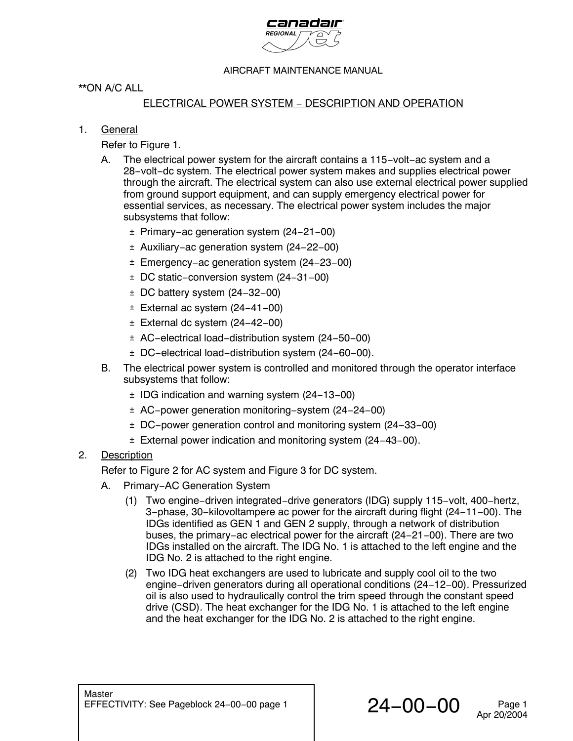
Canadair Regional Jet AMM Chapter 24 Electrical Power System Manual 2005
$39.95 Original price was: $39.95.$25.95Current price is: $25.95.
Complete 2005 Canadair Regional Jet Aircraft Maintenance Manual (AMM) Chapter 24 for the Electrical Power System. This comprehensive factory manual covers AC & DC generation, IDG, APU, ADG, distribution, and all electrical components for the Regional Jet series.
Description
Canadair Regional Jet AMM Chapter 24 Electrical Power System Manual
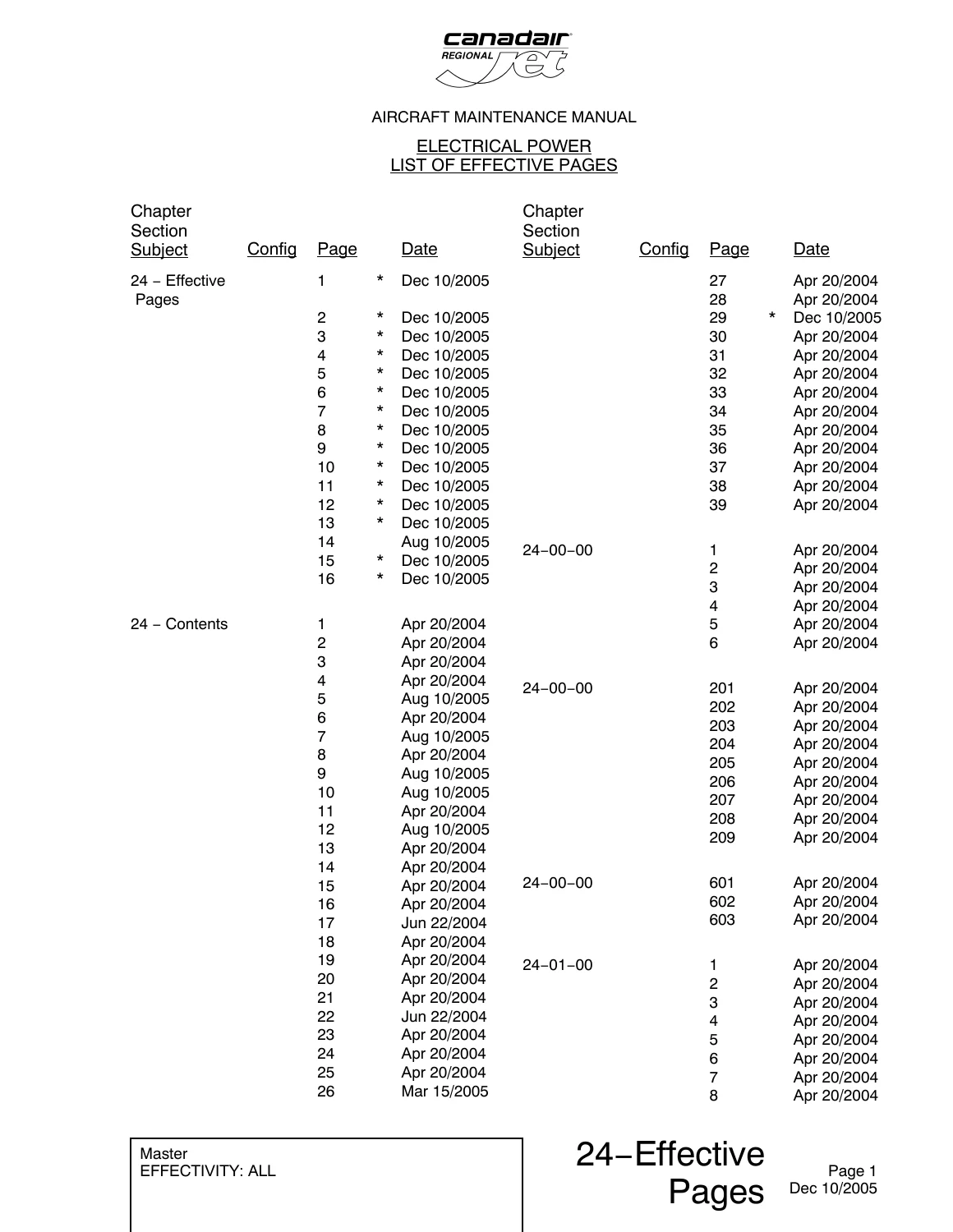
This is the complete Chapter 24: Electrical Power from the official Canadair Regional Jet Aircraft Maintenance Manual (AMM), revision date December 2005. This factory-level document provides every maintenance, repair, removal, installation, testing, and troubleshooting procedure for the entire electrical system on the Canadair Regional Jet. It is a must-have for aircraft maintenance engineers, technicians, and facilities that maintain these aircraft.
File Details
- Manual Type: Aircraft Maintenance Manual (AMM) – Chapter 24
- Document Title: Canadair Regional Jet – Aircraft Maintenance Manual Chapter 24 Electrical Power
- Date & Revision: December 10, 2005
- Language: English
- Page Count: 1,270 Pages
- File Format: PDF
IMAGES PREVIEW
Chapters Covered (24-00-00 to 24-61-00)
- 24-00-00 – Electrical Power System: Description, Operation, Maintenance Practices & Safety
- 24-01-00 – Junction Boxes (JB-2, JB-3, JB-10, JB-11, JB-12, JB-14): Removal, Installation, Retest
- 24-02-00 – Circuit Breaker Panels (CBP-1 to CBP-5): Component Location, Removal, Installation
- 24-10-00 – Generator Drive: IDG Description, Operation, Component Details
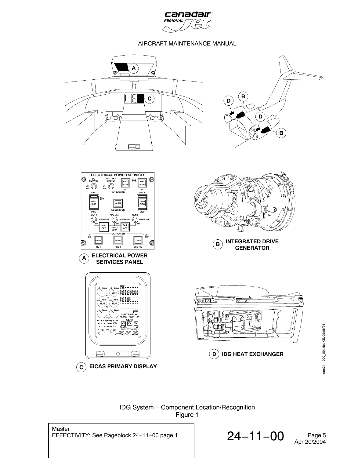
- 24-11-00 – Integrated Drive Generator (IDG): System Operation, Maintenance, Removal/Installation
- 24-11-01 – IDG Removal & Installation: Full procedures with torque specs, cautions & adjustments
- 24-11-03 – IDG Adapter Mounting Plate: Removal, Installation, Inspection
- 24-11-07 – Generator Control Unit (GCU): Removal, Installation
- 24-12-00 – IDG Oil System: Description, Servicing, Inspection, Leak Checks
- 24-12-01 – IDG Charge (Oil-In) Filter Element: Removal, Installation, Inspection
- 24-12-04 – IDG Scavenge (Oil-Out) Filter Element: Removal, Installation, Inspection
- 24-12-13 – IDG Heat Exchanger: Removal, Installation, Pressure Check, Cleaning
- 24-13-00 – IDG Indication & Warning System: EICAS & Electrical Power Services Panel
- 24-20-00 – AC Generation: Description, Load Reduction, Operational Tests
- 24-21-00 – Primary AC Generation System: Operation, Components, Circuit Protection
- 24-22-00 – Auxiliary AC Power Generation System (APU): Operation, Maintenance
- 24-22-01 – APU Generator: Removal, Installation, Inspection, Test
- 24-23-00 – Emergency AC Generation System (ADG): Description, Operation, Troubleshooting
- 24-23-01 – ADG Removal, Installation, Functional Testing, Dry ADG Procedures
- 24-24-00 – AC Power Generation Monitoring System: EICAS Indications
- 24-30-00 – DC Generation: System Description & Operation
- 24-31-00 – DC Static-Conversion System (TRU): Operation, Testing, Adjustments
- 24-32-00 – Battery System: Main & APU Battery, Chargers, Servicing, Removal
- 24-40-00 – External AC/DC Power: Description & Operation
- 24-41-00 – External AC System: Connection, Maintenance, Receptacle Removal
- 24-42-00 – External DC System: Connection, Maintenance, Operation
- 24-50-00 – AC Electrical Load Distribution: System Description, Architecture
- 24-51-00 – AC Electrical Power Distribution: Contactors, Relays, Bus Descriptions
- 24-60-00 – DC Electrical Load Distribution: System Description
- 24-61-00 – DC Electrical Power Distribution: Components, Bus Architecture, Adjustments
Complete Bookmarks
The complete bookmarks in the “Canadair Regional Jet AMM Chapter 24 Electrical Power System Manual 2005” are as follows:
+Chapter 24
+Section 00p. 57
+24-00-00p. 57
+1: ELECTRICAL POWER SYSTEM – DESCRIPTION AND OPERATIONp. 57
+2. Descriptionp. 57
+Electrical Power Systems – Aircraft Configurationp. 60
+AC Electrical Power System – Functional Block Diagramp. 61
+DC Electrical Power System – Functional Block Diagramp. 62
+201: ELECTRICAL POWER SYSTEM – MAINTENANCE PRACTICESp. 63
+Task 24-00-00-861-801 Connect Electrical Power to the Aircraftp. 63
+Task 24-00-00-861-802 Remove Electrical Power to the Aircraftp. 66
+Task 24-00-00-910-801 Electrical/Electronic Safety Precautionsp. 68
+Task 24-00-00-910-802 Electrostatic Discharge Safety Precautionsp. 71
+601: ELECTRICAL POWER – INSPECTION/CHECKp. 73
+Task 24-00-00-760-801 Electrical Check for Zero Currentp. 73
+Section 01p. 151
+24-01-00p. 77
+1: JUNCTION BOXES – DESCRIPTION AND OPERATIONp. 77
+2. Component Detailsp. 77
+3. Operationp. 81
+Junction Box JB-1 – Component Locationsp. 85
+Junction Box JB-2 Component Locationsp. 86
+Junction Boxes JB-4 and JB-5 – Component Locationsp. 87
+Junction Boxes JB-6 and JB-7 – Component Locationsp. 88
+Junction Box JB-8 – Component Locationsp. 89
+Junction Box JB-10 – Component Locationsp. 90
+Junction Box JB-14 – Component Locationsp. 91
+Junction Box JB-1 – Block Diagram (Simplified Schematic)p. 92
+201: JUNCTION BOXES – MAINTENANCE PRACTICESp. 93
+Task 24-01-00-861-801 Connection of Electrical Power to the Junction Boxesp. 94
+Task 24-01-00-861-802 Removal of Electrical Power to the Junction Boxesp. 98
+Junction Boxes – Maintenance Practicesp. 101
+24-01-02p. 103
+401: JUNCTION BOX JB-2 – REMOVAL/INSTALLATIONp. 103
+Task 24-01-02-000-801 Removal of Junction Box JB-2p. 103
+Junction Box JB-2 – Removal/Installationp. 105
+Task 24-01-02-400-801 Installation of Junction Box JB-2p. 106
+501: JUNCTION BOX JB-2 – ADJUSTMENT/TESTp. 107
+Task 24-01-02-750-801 Retest of Junction Box 2p. 107
+24-01-03p. 125
+401: JUNCTION BOX JB-3 – REMOVAL/INSTALLATIONp. 125
+Task 24-01-03-000-801 Removal of Junction Box JB-3p. 125
+Junction Box JB-3 – Removal/Installationp. 127
+Task 24-01-03-400-801 Installation of Junction Box JB-3p. 128
+501: JUNCTION BOX JB-3 – ADJUSTMENT/TESTp. 129
+Task 24-01-03-750-801 Retest of Junction Box 3p. 129
+24-01-10p. 151
+401: JUNCTION BOX JB-10 – REMOVAL/INSTALLATIONp. 151
+Task 24-01-10-000-801 Removal of Junction Box JB-10p. 151
+Junction Box JB-10 – Removal/Installationp. 153
+Task 24-01-10-400-801 Installation of Junction Box JB-10p. 155
+501: JUNCTION BOX JB-10 – ADJUSTMENT/TESTp. 157
+Task 24-01-10-750-801 Retest of Junction Box 10p. 157
+24-01-11p. 193
+401: JUNCTION BOX JB-11 – REMOVAL/INSTALLATIONp. 193
+Task 24-01-11-000-801 Removal of Junction Box JB-11p. 193
+Junction Box JB-11 – Removal/Installationp. 195
+Task 24-01-11-400-801 Installation of Junction Box JB-11p. 197
+501: JUNCTION BOX JB-11 – ADJUSTMENT/TESTp. 199
+Task 24-01-11-750-801 Retest of Junction Box 11p. 199
+24-01-12p. 229
+401: JUNCTION BOX JB-12 – REMOVAL/INSTALLATIONp. 229
+Task 24-01-12-000-801 Removal of Junction Box JB-12p. 229
+Junction Box JB-12 – Removal/Installationp. 231
+Task 24-01-12-400-801 Installation of Junction Box JB-12p. 232
+501: JUNCTION BOX JB-12 – ADJUSTMENT/TESTp. 233
+Task 24-01-12-710-801 Operational Test of Junction Box JB-12p. 233
+Section 02p. 245
+24-02-00p. 245
+1: PANELS, CIRCUIT BREAKER – DESCRIPTION AND OPERATIONp. 245
+Circuit Breaker Panels – Component Location/Recognitionp. 266
+Circuit Breaker Panels – Component Location/Recognitionp. 267
+Circuit Breaker Panels – Component Location/Recognitionp. 268
+Circuit Breaker Panels – Component Location/Recognitionp. 269
+Circuit Breaker Panels – Component Location/Recognitionp. 270
+Circuit Breaker Panels – Component Location/Recognitionp. 271
+Circuit Breaker Panels – Component Location/Recognitionp. 272
+Circuit Breaker Panels – Component Location/Recognitionp. 273
+Circuit Breaker Panels – Component Location/Recognitionp. 274
+Circuit Breaker Panels – Component Location/Recognitionp. 275
+24-02-30p. 277
+401: CIRCUIT BREAKER PANEL CBP-3 – REMOVAL/INSTALLATIONp. 277
+Task 24-02-30-000-801 Removal of Circuit Breaker Panel CBP-3p. 277
+Circuit Breaker Panel CBP-3 – Removal/Installationp. 279
+Task 24-02-30-400-801 Installation of Circuit Breaker Panel CBP-3p. 280
+24-02-40p. 283
+401: CIRCUIT BREAKER PANEL CBP-4 – REMOVAL/INSTALLATIONp. 283
+Task 24-02-40-000-801 Removal of Circuit Breaker Panel CBP-4p. 283
+Circuit Breaker Panel CBP-4 – Removal/Installationp. 285
+Task 24-02-40-400-801 Installation of Circuit Breaker Panel CBP-4p. 286
+Section 10p. 289
+24-10-00p. 289
+1: GENERATOR DRIVE – DESCRIPTION AND OPERATIONp. 289
+2. Descriptionp. 289
+3. Operationp. 289
+Generator Drive System Components – Component Location/Recognitionp. 291
+Section 11p. 293
+24-11-00p. 293
+1: INTEGRATED DRIVE GENERATOR (IDG) SYSTEM – DESCRIPTION AND OPERATIONp. 293
+2. Component Detailsp. 293
+3. Operationp. 295
+IDG System – Component Location/Recognitionp. 297
+Integrated Drive Generator – Component Detailsp. 298
+Integrated Drive Generator System – Functional Block Diagramp. 299
+IDG System – Component Accessp. 300
+201: INTEGRATED DRIVE GENERATOR (IDG) SYSTEM – MAINTENANCE PRACTICESp. 301
+Task 24-11-00-861-801 Energize Primary-AC Generation System (GEN 1 and GEN 2)p. 301
+Task 24-11-00-861-802 Energize Primary-AC Generation System (GEN 1)p. 304
+Task 24-11-00-861-803 Energize Primary-AC Generation System (GEN 2)p. 306
+Task 24-11-00-861-804 Remove Power From the Primary-AC Generation System (GEN 1 and GEN 2)p. 308
+Task 24-11-00-861-805 Remove Power From the Primary-AC Generation System (GEN 1)p. 310
+Task 24-11-00-861-806 Remove Power From the Primary-AC Generation System (GEN 2)p. 312
+24-11-01p. 315
+401: GENERATOR (IDG), INTEGRATED DRIVE – REMOVAL/INSTALLATIONp. 315
+Task 24-11-01-000-801 Removal of the IDGp. 315
+Integrated Drive Generator (IDG), Left Engine – Removal/Installationp. 319
+Integrated Drive Generator (IDG), Right Engine – Removal/Installationp. 321
+Task 24-11-01-400-801 Installation of the IDGp. 323
+501: GENERATOR (IDG), INTEGRATED DRIVE – ADJUSTMENT/TESTp. 331
+Task 24-11-01-710-801 Operational Test of the Left IDG (With Engines Started)p. 331
+Task 24-11-01-710-802 Operational Test of the Right IDG (With Engines Started)p. 334
+Task 24-11-01-710-803 Operational Test of the IDG Disconnect Mechanism With Engines Stoppedp. 337
+Task 24-11-01-710-804 Operational Test of the IDG Disconnect Mechanism With Engines Startedp. 340
+Task 24-11-01-710-805 Set the IDG Disconnect Mechanismp. 342
+Task 24-11-01-720-801 Functional Test of the IDG Disconnect System (With Engines Started)p. 345
+Integrated Drive Generator (IDG) – Adjustment/Testp. 348
+801: CABLES, INTEGRATED DRIVE GENERATOR – REPAIRSp. 349
+Task 24-11-01-350-802 Permanent Repair of the IDG Cablesp. 349
+Task 24-11-01-350-801 Temporary Repair of the IDG Cablesp. 357
+Conduit Installation – Left Enginep. 361
+Conduit Installation – Right Enginep. 362
+Conduit Installation – Right Enginep. 363
+24-11-03p. 365
+401: MOUNTING PLATE, INTEGRATED DRIVE GENERATOR (IDG) ADAPTER – REMOVAL/INSTALLATIONp. 365
+Task 24-11-03-000-801 Removal of the IDG Adapter Mounting Platep. 365
+IDG Adapter Mounting Plate – Removal/Installationp. 367
+Task 24-11-03-400-801 Installation of the IDG Adapter Mounting Platep. 368
+601: MOUNTING PLATE, INTEGRATED DRIVE GENERATOR (IDG) ADAPTER – INSPECTION/CHECKp. 371
+Task 24-11-03-210-801 Inspection of the IDG Mounting Platep. 371
+IDG Adapter Mounting Plate – Inspection/Checkp. 373
+24-11-07p. 375
+401: CONTROL UNIT (GCU), GENERATOR – REMOVAL/INSTALLATIONp. 375
+Task 24-11-07-000-801 Removal of the GCUp. 375
+Generator Control Unit – Removal/Installationp. 377
+Task 24-11-07-400-801 Installation of the GCUp. 378
+Section 12p. 381
+24-12-00p. 381
+1: OIL SYSTEM, INTEGRATED DRIVE GENERATOR (IDG) – DESCRIPTION AND OPERATIONp. 381
+2. Component Detailsp. 381
+3. Operationp. 384
+B. Trim-Speed Control Mechanismp. 385
+IDG Oil-Supply System – Component Location/Recognitionp. 388
+IDG Oil Supply Connector and Port Locationsp. 389
+IDG Heat Exchanger – Component Detailsp. 390
+Controls and Indicators – Component Detailsp. 391
+IDG Oil-Supply System – Hydraulic Schematicp. 392
+IDG Oil-Supply System – Component Accessp. 393
+301: OIL SYSTEM, INTEGRATED DRIVE GENERATOR (IDG) – SERVICINGp. 395
+Task 24-12-00-680-801 Draining of the IDG Oil Systemp. 395
+IDG Oil System – Drainingp. 398
+601: OIL SYSTEM, INTEGRATED DRIVE GENERATOR (IDG) – INSPECTION/CHECKp. 399
+Task 24-12-00-210-802 Visual Inspection of the IDG Oil-System Levelp. 399
+IDG Oil-Level Sight Glass – Inspection/Checkp. 402
+Task 24-12-00-210-803 Leak Check of the IDG Oil Systemp. 403
+Location of Possible IDG Oil Leaks – Inspection/Checkp. 406
+Task 24-12-00-210-804 Visual Check of the IDG Oil Filter Differential Pressure Indicatorsp. 407
+Integrated Drive Generator (IDG Oil System) – Inspection/Checkp. 410
+24-12-01p. 411
+401: FILTER ELEMENT, INTEGRATED DRIVE GENERATOR (IDG) CHARGE (OIL-IN) – REMOVAL/INSTALLATIONp. 411
+Task 24-12-01-000-801 Removal of the IDG Charge (Oil-In) Filter Elementp. 411
+IDG Charge (Oil-In) Filter Element – Removal/Installationp. 413
+Task 24-12-01-400-801 Installation of the IDG Charge (Oil-In) Filter Elementp. 414
+601: FILTER ELEMENT, INTEGRATED DRIVE GENERATOR (IDG) CHARGE (OIL-IN) – INSPECTION/CHECKp. 417
+Task 24-12-01-210-801 Inspection of the IDG Charge Filter Elementp. 417
+24-12-04p. 421
+401: FILTER ELEMENT, INTEGRATED DRIVE GENERATOR (IDG) SCAVENGE (OIL-OUT) – REMOVAL/INSTALLATIONp. 421
+Task 24-12-04-000-801 Removal of the IDG Scavenge (Oil-Out) Filter Elementp. 421
+IDG Scavenge (Oil-Out) Filter Element – Removal/Installationp. 423
+Task 24-12-04-400-801 Installation of the IDG Scavenge (Oil-Out) Filter Elementp. 424
+601: FILTER ELEMENT, INTEGRATED DRIVE GENERATOR (IDG) SCAVENGE (OIL-OUT) – INSPECTION/CHECKp. 427
+Task 24-12-04-210-801 Inspection of the IDG Scavenge Filter Elementp. 427
+24-12-05p. 431
+401: FILTER ASSEMBLY, INTEGRATED DRIVE GENERATOR (IDG) SCAVENGE (OIL-OUT) – REMOVAL/INSTALLATIONp. 431
+Task 24-12-05-000-801 Removal of the IDG Scavenge (Oil-Out) Filter Assemblyp. 431
+IDG Scavenge Filter Assembly – Removal/Installationp. 433
+Task 24-12-05-400-801 Installation of the IDG Scavenge (Oil-Out) Filter Assemblyp. 434
+24-12-06p. 437
+401: INDICATORS, INTEGRATED DRIVE GENERATOR (IDG) DIFFERENTIAL-PRESSURE – REMOVAL/INSTALLATIONp. 437
+Task 24-12-06-000-801 Removal of the IDG Scavenge-Differential Pressure-Indicatorp. 437
+IDG Scavenge-Differential Pressure-Indicator – Removal/Installationp. 439
+Task 24-12-06-400-801 Installation of the IDG Scavenge-Differential Pressure-Indicatorp. 440
+Task 24-12-06-000-802 Removal of the IDG Charge-Differential Pressure-Indicatorp. 443
+IDG Charge-Differential Pressure-Indicator – Removal/Installationp. 445
+Task 24-12-06-400-802 Installation of the IDG Charge-Differential Pressure-Indicatorp. 446
+601: INDICATORS, INTEGRATED DRIVE GENERATOR (IDG) DIFFERENTIAL-PRESSURE – INSPECTION/CHECKp. 449
+Task 24-12-06-210-801 Visual Inspection of the Differential Pressure of the IDG Systemp. 449
+Differential Pressure Indicators – Inspection/Checkp. 452
+24-12-07p. 453
+401: STANDPIPE ASSEMBLY, INTEGRATED DRIVE GENERATOR (IDG) OVERFILL – REMOVAL/INSTALLATIONp. 453
+Task 24-12-07-000-801 Removal of the IDG Overfill Standpipe Assemblyp. 453
+IDG Overfill Standpipe Assembly – Removal/Installationp. 455
+Task 24-12-07-400-801 Installation of the IDG Overfill Standpipe Assemblyp. 456
+24-12-09p. 459
+401: INDICATOR, INTEGRATED DRIVE GENERATOR (IDG) LOW OIL-LEVEL – REMOVAL/INSTALLATIONp. 459
+Task 24-12-09-000-801 Removal of the IDG Low Oil-Level Indicatorp. 459
+IDG Low Oil Level Indicator – Removal/Installationp. 460
+Task 24-12-09-400-801 Installation of the IDG Overfill Standpipe Assemblyp. 461
+24-12-13p. 463
+401: HEAT EXCHANGER, INTEGRATED DRIVE GENERATOR (IDG) – REMOVAL/INSTALLATIONp. 463
+Task 24-12-13-000-801 Removal of the IDG Heat Exchangerp. 463
+IDG Heat Exchanger – Removal/Installationp. 465
+Task 24-12-13-400-801 Installation of the IDG Heat Exchangerp. 466
+601: HEAT EXCHANGER, INTEGRATED DRIVE GENERATOR (IDG) – INSPECTION/CHECKp. 471
+Task 24-12-13-780-801 Pressure Check of the IDG Heat Exchangerp. 471
+IDG Heat Exchanger – Inspection/Checkp. 476
+Task 24-12-13-790-801 Leak Check of the IDG Heat Exchangerp. 477
+Task 24-12-13-210-801 Visual Inspection of the IDG Heat Exchangerp. 480
+701: HEAT EXCHANGER, INTEGRATED DRIVE GENERATOR (IDG) – CLEANING/PAINTINGp. 483
+Task 24-12-13-100-801 Cleaning of the IDG Heat Exchangerp. 483
+IDG Heat Exchanger – Cleaning/Paintingp. 491
+Section 13p. 493
+24-13-00p. 493
+1: INTEGRATED DRIVE GENERATOR INDICATION AND WARNING SYSTEM – DESCRIPTION AND OPERATIONp. 493
+2. Component Detailsp. 493
+3. Operationp. 495
+Integrated Drive Generator (IDG) Indication and Monitoring – Component Location/Recognitionp. 498
+ELECTRICAL POWER SERVICES Panel – Component Detailsp. 499
+EICAS Display (Generator Drive) – Component Detailsp. 500
+Integrated Drive Generator (IDG) Indication and Monitoring – Functional Block Diagramp. 501
+24-13-01p. 503
+401: PANEL, ELECTRICAL POWER SERVICES – REMOVAL/INSTALLATIONp. 503
+Task 24-13-01-000-801 Removal of the ELECTRICAL POWER SERVICES Panelp. 503
+ELECTRICAL POWER SERVICES Panel – Removal/Installationp. 504
+Task 24-13-01-400-801 Installation of the ELECTRICAL POWER SERVICES Panelp. 505
+24-13-05p. 507
+401: TEMPERATURE BULB, IDG OIL-OUT – REMOVAL/INSTALLATIONp. 507
+Task 24-13-05-000-801 Removal of the IDG Oil-Out Temperature-Bulbp. 507
+Temperature Bulb, IDG Oil-Out – Removal/Installationp. 509
+Task 24-13-05-400-801 Installation of the IDG Oil-Out Temperature-Bulbp. 510
+Section 20p. 513
+24-20-00p. 513
+1: AC GENERATION – DESCRIPTION AND OPERATIONp. 513
+2. Descriptionp. 513
+AC Generation – Component Location/Recognitionp. 515
+201: AC GENERATION – MAINTENANCE PRACTICESp. 517
+Task 24-20-00-720-801 Electrical Load Reduction (GEN 1)p. 517
+Task 24-20-00-720-802 Electrical Load Reduction (GEN 2)p. 521
+501: AC GENERATION – ADJUSTMENT/TESTp. 525
+Task 24-20-00-710-801 Operational Test of the AC Generation Systemp. 525
+Task 24-20-00-720-803 Functional Test of the AC Power Transfer Circuitp. 529
+Task 24-20-00-710-803 Operational Test of the GCU Overvoltage Test Circuitsp. 531
+Section 21p. 533
+24-21-00p. 533
+1: PRIMARY AC POWER GENERATION SYSTEM – DESCRIPTION AND OPERATIONp. 533
+2. Component Detailsp. 533
+3. Operationp. 537
+Primary-AC Power-Generation System – Component Location/Recognitionp. 545
+Integrated Drive Generator – Component Detailsp. 547
+Generator Control Unit – Component Detailsp. 548
+Generator Control Unit – Block Diagramp. 549
+Main Electrical Distribution Panel (JB1) – Component Detailsp. 550
+Primary AC Generation – Functional Block Diagramp. 551
+Integrated Drive Generator – Electrical Schematicp. 552
+Main Generator – Block Diagramp. 553
+CTA Line Contactor and CTA Transfer Contactor – Electrical Schematicp. 554
+Generator Control Unit – Electrical Schematicp. 555
+Voltage Regulator Circuit – Electrical Schematicp. 557
+Generator Control Relay Circuit – Electrical Schematicp. 558
+Generator Line Contactor Relay Circuit – Electrical Schematicp. 559
+Overload Monitor Circuit – Electrical Schematicp. 560
+Bus-Tie Breaker-Relay Circuit – Electrical Schematicp. 561
+Primary-AC Power-Generation System – Component Accessp. 562
+Section 22p. 563
+24-22-00p. 563
+1: AUXILIARY AC POWER GENERATION SYSTEM – DESCRIPTION AND OPERATIONp. 563
+2. Component Detailsp. 563
+3. Operationp. 565
+Auxiliary-AC Power-Generation System – Component Location/Recognitionp. 568
+Auxiliary AC Generation – Functional Block Diagramp. 569
+201: AUXILIARY AC POWER GENERATION SYSTEM – MAINTENANCE PRACTICESp. 571
+Task 24-22-00-861-801 Energize Auxiliary-AC Generation System in the Standard Configurationp. 571
+Task 24-22-00-861-802 Energize Auxiliary-AC Generation System in the Service Configurationp. 573
+Task 24-22-00-861-803 Remove Power From the Auxiliary-AC Generation System in the Standard Configurationp. 574
+Task 24-22-00-861-804 Remove Power From the Auxiliary-AC Generation System in the Service Configurationp. 576
+24-22-01p. 579
+401: GENERATOR, AUXILIARY POWER UNIT (APU) – REMOVAL/INSTALLATIONp. 579
+Task 24-22-01-000-801 Removal of the APU Generatorp. 579
+APU Generator – Removal/Installationp. 582
+Task 24-22-01-400-801 Installation of the APU Generatorp. 584
+501: AUXILIARY POWER UNIT (APU) GENERATOR SYSTEM – ADJUSTMENT/TESTp. 589
+Task 24-22-01-710-801 Operational Test of the APU Generator Systemp. 589
+601: GENERATOR, AUXILIARY POWER UNIT (APU) – INSPECTION/CHECKp. 591
+Task 24-22-01-210-801 Visual Inspection of the APU Generatorp. 591
+APU Generator – Inspection/Checkp. 593
+Section 23p. 595
+24-23-00p. 595
+1: EMERGENCY AC POWER GENERATION SYSTEM – DESCRIPTION AND OPERATIONp. 595
+2. Component Detailsp. 595
+3. Operationp. 601
+Emergency-AC Power-Generation System – Component Location/Recognitionp. 606
+Emergency-AC Power-Generation System – Component Location/Recognitionp. 607
+Air Driven Generator – Functional Block Diagramp. 608
+ADG Automatic Deployment – Functional Diagramp. 609
+ADG Generator Control Unit – Simplified Electrical Schematicp. 610
+Dry ADG Generator Control Unit – Simplified Electrical Schematicp. 611
+ADG Automatic Deployment Power Transfer – Simplified Electrical Schematicp. 612
+ADG Manual Deployment Power Transfer – Simplified Electrical Schematicp. 613
+Emergency AC-Power Generation-System – Component Accessp. 614
+24-23-01p. 615
+201: GENERATOR, AIR DRIVEN (ADG) – MAINTENANCE PRACTICESp. 615
+Task 24-23-01-840-801 Lowering of the ADGp. 615
+Air Driven Generator – Maintenance Practicesp. 618
+Task 24-23-01-840-804 Manual Lowering of the Dry ADGp. 619
+Dry Air Driven Generator – Maintenance Practicesp. 621
+Task 24-23-01-840-807 Automatic Deployment of the Dry ADGp. 622
+Task 24-23-01-840-802 Retraction of the ADG After Manual Deploymentp. 625
+Task 24-23-01-840-803 Retraction of the ADG After Automatic Deploymentp. 628
+Task 24-23-01-840-805 Retraction of the Dry ADG After Deploymentp. 633
+401: GENERATOR, AIR DRIVEN (ADG) – REMOVAL/INSTALLATIONp. 637
+Task 24-23-01-000-801 Removal of the ADGp. 637
+Air Driven Generator – Removal/Installationp. 639
+Task 24-23-01-400-801 Installation of the ADGp. 640
+Task 24-23-01-020-803 Removal of the Dry ADGp. 644
+Dry Air Driven Generator – Removal/Installationp. 646
+Task 24-23-01-420-801 Installation of the Dry ADGp. 648
+Dry Air Driven Generator – Downlock Pin Adjustmentp. 654
+Task 24-23-01-948-801 Summary of Reports of Non-Conformance for 24-23-01 Removal/Installation Pageblockp. 655
+501: GENERATOR (ADG), AIR DRIVEN – ADJUSTMENT/TESTp. 657
+Task 24-23-01-720-802 Functional Test of the Hydraulic ADGp. 657
+ADG Backdrive Test Equipment Installationp. 668
+Task 24-23-01-720-803 Functional Test of the Dry ADGp. 669
+Dry ADG Backdrivep. 677
+601: GENERATOR (ADG), AIR DRIVEN – INSPECTION/CHECKp. 679
+Task 24-23-01-210-802 Visual Inspection of the ADGp. 679
+Air Driven Generator (ADG) – Inspection/Checkp. 682
+Task 24-23-01-210-801 Contamination Check of the ADG Oil Systemp. 684
+Task 24-23-01-790-802 Oil Leak Check of the ADG Componentsp. 686
+Task 24-23-01-210-803 Visual Inspection of the Dry ADGp. 688
+Dry Air Driven Generator – Inspection/Checkp. 691
+Task 24-23-01-790-803 Oil Leak Check of Dry ADG Componentsp. 693
+Task 24-23-01-220-801 Dry ADG Mechanical Components Checksp. 695
+Release Cable/Uplock Assembly – Inspection Checkp. 701
+Blade Rotation Control Cable Assembly – Inspection/Checkp. 702
+Dry ADG Door Operating Mechanism – Inspection/Checkp. 703
+701: GENERATOR (ADG), AIR DRIVEN – CLEANING/PAINTINGp. 705
+Task 24-23-01-160-801 Cleaning of the Turbine Blades Before ADG Retractionp. 705
+Air Driven Generator – Cleaning/Paintingp. 707
+Task 24-23-01-160-803 Cleaning of the Turbine Blades before Dry ADG Retractionp. 708
+Dry Air Driven Generator – Cleaning/Paintingp. 710
+Task 24-23-01-160-802 Cleaning of the Air-Inlet Screenp. 711
+24-23-02p. 713
+401: DOWNLOCK PIN, AIR DRIVEN GENERATOR (ADG)p. 713
+Task 24-23-02-020-801 Removal of the Dry ADG Downlock Pinp. 713
+Dry ADG Downlock Pin – Removal/Installationp. 714
+Task 24-23-02-420-801 Installation of the Dry ADG Downlock Pinp. 715
+24-23-03p. 719
+401: FILTER ELEMENT, AIR DRIVEN GENERATOR (ADG) OIL – REMOVAL/INSTALLATIONp. 719
+Task 24-23-03-000-801 Removal of the ADG Oil Filter Elementp. 719
+ADG Oil Filter-Element – Removal/Installationp. 721
+Task 24-23-03-400-801 Installation of the ADG Oil Filter Elementp. 722
+601: FILTER ELEMENT, AIR DRIVEN GENERATOR (ADG) OIL – INSPECTION/CHECKp. 725
+Task 24-23-03-210-801 Visual Inspection of the ADG Oil Filter Elementp. 725
+24-23-04p. 729
+401: EJECTION JACK, AIR DRIVEN GENERATOR (ADG) – REMOVAL/INSTALLATIONp. 729
+Task 24-23-04-000-801 Removal of the ADG Ejection Jackp. 729
+ADG Ejection Jack – Removal/Installationp. 731
+Task 24-23-04-020-802 Removal of the Dry ADG Ejection Jackp. 732
+Dry ADG Ejection Jack – Removal/Installationp. 734
+Task 24-23-04-400-801 Installation of the ADG Ejection Jackp. 735
+Task 24-23-04-420-801 Installation of the Dry ADG Ejection Jackp. 738
+Task 24-23-04-948-801 Summary of Reports of Non-Conformance for 24-23-04 Removal/Installation Pageblockp. 741
+501: EJECTION JACK, AIR DRIVEN GENERATOR (ADG) – ADJUSTMENT/TESTp. 743
+Task 24-23-04-820-801 Adjustment of the ADG Ejection Jackp. 743
+ADG Ejection Jack Adjustmentp. 746
+Task 24-23-04-820-802 Adjustment of the Dry ADG Ejection Jackp. 747
+Dry ADG Ejection Jack Adjustmentp. 750
+601: EJECTION JACK, AIR DRIVEN GENERATOR (ADG) – INSPECTION/CHECKp. 751
+Task 24-23-04-220-801 Measure the Travel of the ADG Ejection Jackp. 751
+Ejection Jack, Air Driven Generator (ADG) – Inspection/Checkp. 754
+24-23-07p. 755
+401: GENERATOR CONTROL UNIT, AIR DRIVEN GENERATOR (ADG) – REMOVAL/INSTALLATIONp. 755
+Task 24-23-07-000-801 Removal of the ADG Generator Control Unitp. 755
+ADG Generator Control Unit – Removal/Installationp. 756
+Task 24-23-07-020-801 Removal of the Dry ADG Generator Control Unitp. 757
+Dry ADG Generator Control Unit – Removal Installationp. 758
+Task 24-23-07-400-801 Installation of the ADG Generator Control Unitp. 759
+Task 24-23-07-420-801 Installation of the Dry ADG Generator Control Unitp. 761
+501: GENERATOR CONTROL UNIT, AIR DRIVEN GENERATOR (ADG) – ADJUSTMENT/TESTp. 763
+Task 24-23-07-710-801 Operational test of the Generator Control Unitp. 763
+24-23-10p. 767
+401: CABLE, AIR DRIVEN GENERATOR (ADG) MANUAL DEPLOYMENT – REMOVAL/INSTALLATIONp. 767
+Task 24-23-10-000-801 Removal of the ADG Manual-Deployment Cablep. 767
+ADG Manual-Deployment Cable – Removal/Installationp. 770
+ADG Manual-Deployment Cable – Removal/Installationp. 771
+Task 24-23-10-020-802 Removal of the Dry ADG Manual-Deployment Cablep. 773
+Dry ADG Manual-Deployment Release Cable – Removal/Installationp. 776
+Task 24-23-10-400-801 Installation of the ADG Manual-Deployment Cablep. 777
+Task 24-23-10-420-802 Installation of the Dry ADG Manual-Deployment Release Cablep. 781
+24-23-13p. 785
+401: LEVER ASSEMBLY, AIR DRIVEN GENERATOR (ADG) MANUAL DEPLOYMENT – REMOVAL/INSTALLATIONp. 785
+Task 24-23-13-000-801 Removal of the ADG Manual Deployment Lever Assemblyp. 785
+ADG Manual-Deployment Lever Assembly – Removal/Installationp. 787
+Task 24-23-13-020-801 Removal of the Dry ADG Manual Deployment Leverp. 788
+Dry ADG Manual-Deployment Lever Assembly – Removal/Installationp. 790
+Task 24-23-13-400-801 Installation of the ADG Manual Deployment Lever Assemblyp. 791
+Task 24-23-13-420-801 Installation of the Dry ADG Manual Deployment Release Leverp. 793
+24-23-15p. 795
+401: PANEL, ADG AUTO DEPLOY CONTROL – REMOVAL/INSTALLATIONp. 795
+Task 24-23-15-000-801 Removal of the ADG AUTO DEPLOY CONTROL Panelp. 795
+ADG AUTO DEPLOY CONTROL Panel – Removal/Installationp. 797
+Task 24-23-15-400-801 Installation of the ADG AUTO DEPLOY CONTROL Panelp. 798
+501: PANEL, ADG AUTO DEPLOY CONTROL – ADJUSTMENT/TESTp. 801
+Task 24-23-15-710-801 Operational Test of the ADG Auto-Deploy Control Panelp. 801
+24-23-16p. 805
+501: LEVER SWITCHES, AIR-DRIVEN GENERATOR (ADG) MANUAL-RELEASE – ADJUSTMENT/TESTp. 805
+Task 24-23-16-720-801 Functional Test of the ADG Manual-Release Lever Switchesp. 805
+24-23-19p. 809
+401: PUMP ASSEMBLY, AIR DRIVEN GENERATOR (ADG) RESTOW – REMOVAL/INSTALLATIONp. 809
+Task 24-23-19-000-801 Removal of the ADG Restow Pump Assemblyp. 809
+ADG Restow Pump Assembly – Removal/Installationp. 811
+Task 24-23-19-020-801 Removal of the Dry ADG Restow Pump Assemblyp. 812
+Dry ADG Restow Pump – Removal/Installationp. 814
+Task 24-23-19-400-801 Installation of the ADG Restow Pump Assemblyp. 815
+Task 24-23-19-420-801 Installation of the Dry ADG Restow Pumpp. 818
+24-23-22p. 821
+201: UPLOCK ACTUATOR, AIR DRIVEN GENERATOR (ADG) – MAINTENANCE PRACTICESp. 821
+Task 24-23-22-550-801 Safety Precautions for Removal and Storage of the ADG Squibp. 821
+401: AIR DRIVEN GENERATOR (ADG) DEPLOYMENT SQUIB – REMOVAL/INSTALLATIONp. 825
+Task 24-23-22-040-801 Deactivation of the ADG Deployment Squibp. 825
+ADG Deployment Squib – Deactivation/Reactivationp. 828
+Task 24-23-22-440-801 Reactivation of the ADG Deployment Squibp. 829
+Task 24-23-22-000-801 Removal of the ADG Deployment Squibp. 830
+Main and APU Batteries – Disconnect/Connectp. 832
+ADG Deployment Squib – Removal/Installationp. 833
+Task 24-23-22-400-801 Installation of the ADG Deployment Squibp. 834
+24-23-25p. 837
+401: UPLOCK ASSEMBLY, AIR DRIVEN GENERATOR (ADG) – REMOVAL/INSTALLATIONp. 837
+Task 24-23-25-000-801 Removal of the ADG Uplock Assemblyp. 837
+ADG Uplock Assembly – Removal/Installationp. 839
+Task 24-23-25-020-801 Removal of the Dry ADG Uplock Assemblyp. 840
+Dry ADG Uplock Assembly – Removal/Installationp. 841
+Task 24-23-25-400-801 Installation of the ADG Uplock Assemblyp. 842
+Task 24-23-25-420-801 Installation of the Dry ADG Uplock Assemblyp. 844
+501: UPLOCK ASSEMBLY, AIR DRIVEN GENERATOR (ADG) – ADJUSTMENT/TESTp. 847
+Task 24-23-25-820-801 Adjustment of the ADG Uplock Assemblyp. 847
+ADG Uplock Assembly – Adjustment/Testp. 850
+ADG Uplock Assembly Roller and Gap – Adjustment/Testp. 851
+Task 24-23-25-820-802 Adjustment of the Dry ADG Uplock Assemblyp. 852
+Dry ADG Uplock Assembly – Adjustment/Testp. 855
+Dry ADG Uplock Assembly Roller and Gap – Adjustment/Testp. 856
+24-23-28p. 857
+401: CABLE ASSEMBLY, AIR DRIVEN GENERATOR (ADG) CONTROL – REMOVAL/INSTALLATIONp. 857
+Task 24-23-28-000-801 Removal of the ADG Control Cable Assemblyp. 857
+ADG Control Cable Assembly – Removal/Installationp. 859
+Task 24-23-28-020-801 Removal of the Dry ADG Control Cable Assemblyp. 860
+Dry ADG Control Cable Assembly – Removal/Installationp. 861
+Task 24-23-28-400-801 Installation of the ADG Control Cable Assemblyp. 862
+Task 24-23-28-420-801 Installation of the Dry ADG control Cable Assemblyp. 864
+501: CABLE ASSEMBLY, AIR DRIVEN GENERATOR (ADG) CONTROL – ADJUSTMENT/TESTp. 867
+Task 24-23-28-820-801 Adjustment of the ADG Turbine Blade Lockpinp. 867
+ADG Turbine Blade Lockpin Adjustmentp. 872
+Task 24-23-28-820-802 Adjustment of the Dry ADG Turbine Blade Lockpinp. 873
+Dry ADG Turbine Blade Lockpin Adjustmentp. 876
+Task 24-23-28-750-801 ADG Clearance Checksp. 877
+Task 24-23-28-220-801 Dry ADG Clearance Checksp. 880
+Dry ADG Clearance Checksp. 883
+24-23-31p. 885
+401: CONTACTOR, EMERGENCY HYDRAULIC-POWER-TRANSFER (K1XC) – REMOVAL/INSTALLATIONp. 885
+Task 24-23-31-000-801 Removal of the Emergency Hydraulic-Power-Transfer Contactor (K1XC)p. 885
+Contactor, Emergency Hydraulic-Power-Transfer (K1XC) – Removal/Installationp. 887
+Task 24-23-31-400-801 Installation of the Emergency Hydraulic-Power-Transfer Contactor (K1XC)p. 888
+501: CONTACTOR, EMERGENCY HYDRAULIC-POWER-TRANSFER (K1XC) – ADJUSTMENT/TESTp. 891
+Task 24-23-31-720-801 Functional Test of the Emergency Hydraulic-Power-Transfer Contactor (K1XC)p. 891
+Section 24p. 897
+24-24-00p. 897
+1: AC-POWER GENERATION-MONITORING SYSTEM – DESCRIPTION AND OPERATIONp. 897
+2. Component Detailsp. 897
+3. Operationp. 899
+AC-Power Generation-Monitoring System – Component Location/Recognitionp. 903
+ELECTRICAL POWER SERVICES Panel (Auxiliary AC-Power Generation) – Component Detailsp. 904
+EICAS Display (Auxiliary AC Power-Generation) – Component Detailsp. 905
+ADG AUTO DEPLOY CONTROL – Front Panel Component Detailsp. 906
+EICAS Display (Emergency-AC Power Generation) – Component Detailsp. 907
+24-24-01p. 909
+401: ASSEMBLY, EXTERNAL SERVICE-PANEL – REMOVAL/INSTALLATIONp. 909
+Task 24-24-01-000-801 Removal of the External Service-Panel Assemblyp. 909
+External Service-Panel Assembly – Removal/Installationp. 911
+Task 24-24-01-400-801 Installation of the External Service-Panel Assemblyp. 912
+501: ASSEMBLY, EXTERNAL SERVICE-PANEL – ADJUSTMENT/TESTp. 915
+Task 24-24-01-710-801 Operational Test of the External Service Panel Assemblyp. 915
+Section 30p. 919
+24-30-00p. 919
+1: DC GENERATION – DESCRIPTION AND OPERATIONp. 919
+2. Descriptionp. 919
+3. Operationp. 919
+DC Generation System – Component Location/Recognitionp. 920
+Section 31p. 921
+24-31-00p. 921
+1: DC STATIC-CONVERSION SYSTEM – DESCRIPTION AND OPERATIONp. 921
+2. Descriptionp. 921
+3. Operationp. 923
+Transformer Rectifier Unit – Description/Locationp. 926
+Transformer Rectifier Unit – Electrical Schematicp. 927
+Transformer Rectifier Unit – Electrical Schematicp. 928
+DC Static-Conversion System – Simplified Block Diagramp. 929
+DC Static Conversion – Functional Block Diagramp. 930
+Bus Tie Operation – Block Diagramp. 931
+DC Static-Conversion System – Component Accessp. 932
+501: DC STATIC-CONVERSION SYSTEM – ADJUSTMENT/TESTp. 933
+Task 24-31-00-710-801 Operational Test of the DC Static-Conversion Systemp. 933
+Task 24-31-00-720-801 Functional Test of the DC Power Distributionp. 938
+DC Static-Conversion System – Adjustment/Testp. 940
+Task 24-31-00-710-803 Operational Test of the Battery Circuitp. 941
+DC Static-Conversion System – Adjustment/Testp. 943
+24-31-01p. 945
+401: UNIT (TRU), TRANSFORMER RECTIFIER – REMOVAL/INSTALLATIONp. 945
+Task 24-31-01-000-801 Removal of the TRUp. 945
+Transformer Rectifier Unit – Removal/Installationp. 947
+Task 24-31-01-400-801 Installation of the TRUp. 948
+501: TRANSFORMER RECTIFIER UNIT (TRU) – ADJUSTMENT/TESTp. 951
+Task 24-31-01-710-801 Operational Test of the TRUp. 951
+Task 24-31-01-710-802 Operational Test of the Essential TRUs and Power Transfer Circuitsp. 954
+Transformer Rectifier Unit (TRU) – Adjustment/Testp. 957
+Task 24-31-01-710-803 Operational Test of the Essential TRU 1 and 2p. 958
+Transformer Rectifier Unit (TRU) – Adjustment/Testp. 960
+24-31-02p. 961
+501: TRANSFORMER RECTIFIER UNIT (TRU) FAN – ADJUSTMENT/TESTp. 961
+Task 24-31-02-710-801 Operational Test of the TRU Fansp. 961
+Transformer Rectifier Unit (TRU) Fan – Adjustment/Testp. 963
+Section 32p. 965
+24-32-00p. 965
+1: BATTERY SYSTEM – DESCRIPTION AND OPERATIONp. 965
+2. Component Detailsp. 965
+3. Operationp. 967
+Battery System – Component Location/Recognitionp. 976
+Batteries – Component Detailsp. 977
+Main and APU Battery Chargers – Component Detailsp. 978
+Securaplane Battery Chargerp. 979
+Battery System – Functional Block Diagramp. 980
+Battery Charger System – Functional Block Diagramp. 981
+201: BATTERY SYSTEM – MAINTENANCE PRACTICESp. 983
+Task 24-32-00-861-801 Energize Battery System in the Standard Configurationp. 983
+Task 24-32-00-861-802 Energize Battery System in the Service Configurationp. 985
+Task 24-32-00-861-803 Remove Power From the Battery System in the Standard Configurationp. 987
+Task 24-32-00-861-804 Remove Power From the Battery System in the Service Configurationp. 988
+401: BATTERY SYSTEM – REMOVAL/INSTALLATIONp. 989
+Task 24-32-00-040-803 Deactivation of the Main Batteryp. 989
+Task 24-32-00-040-804 Deactivation of the APU Batteryp. 991
+Task 24-32-00-440-802 Reactivation of the Main Batteryp. 993
+Task 24-32-00-440-801 Reactivation of the APU Batteryp. 994
+24-32-01p. 995
+301: MAIN BATTERY – SERVICINGp. 995
+Task 24-32-01-613-801 Electrolyte Level Adjustment in the Main Batteryp. 995
+401: MAIN BATTERY – REMOVAL/INSTALLATIONp. 997
+Task 24-32-01-000-801 Removal of the Main Batteryp. 997
+Main Battery – Removal/Installationp. 999
+Task 24-32-01-400-801 Installation of the Main Batteryp. 1000
+501: MAIN BATTERY – ADJUSTMENT/TESTp. 1003
+Task 24-32-01-710-801 Operational Test of the Main Batteryp. 1003
+601: MAIN BATTERY – INSPECTION/CHECKp. 1005
+Task 24-32-01-210-801 Visual Inspection of the Main Batteryp. 1005
+Main Battery – Inspection/Checkp. 1008
+24-32-02p. 1009
+301: AUXILIARY POWER UNIT (APU) BATTERY – SERVICINGp. 1009
+Task 24-32-02-613-801 Electrolyte Level Adjustment in the APU Batteryp. 1009
+401: AUXILIARY POWER UNIT (APU) BATTERY – REMOVAL/INSTALLATIONp. 1011
+Task 24-32-02-000-801 Removal of the APU Batteryp. 1011
+APU Battery – Removal/Installationp. 1013
+Task 24-32-02-400-801 Installation of the APU Batteryp. 1014
+501: AUXILIARY POWER UNIT (APU) BATTERY – ADJUSTMENT/TESTp. 1017
+Task 24-32-02-710-801 Operational Test of the APU Batteryp. 1017
+601: AUXILIARY POWER UNIT (APU) BATTERY – INSPECTION/CHECKp. 1019
+Task 24-32-02-210-801 Visual Inspection of the APU Batteryp. 1019
+APU Battery – Inspection/Checkp. 1022
+24-32-03p. 1023
+401: BATTERY CHARGERS – REMOVAL/INSTALLATIONp. 1023
+Task 24-32-03-000-801 Removal of the Battery Chargersp. 1023
+Acme Battery Charger – Removal/Installationp. 1025
+Securaplane Battery Charger – Removal/Installationp. 1026
+Task 24-32-03-400-801 Installation of the Battery Chargersp. 1027
+501: BATTERY CHARGERS – ADJUSTMENT/TESTp. 1031
+Task 24-32-03-710-801 Operational Test of the APU Battery Chargerp. 1031
+Task 24-32-03-710-802 Operational Test of the Main Battery Chargerp. 1033
+Task 24-32-03-720-801 Functional Test of the APU Battery Chargerp. 1034
+Task 24-32-03-720-802 Functional Test of the Main Battery Chargerp. 1037
+Section 33p. 1041
+24-33-00p. 1041
+1: DC POWER GENERATION CONTROL AND MONITORING SYSTEM – DESCRIPTION AND OPERATIONp. 1041
+2. Component Detailsp. 1041
+3. Operationp. 1047
+DC Power-Generation Control and Monitoring-System – Component Location/Recognitionp. 1049
+ELECTRICAL POWER SERVICES Panel (DC Static-Conversion System) – Component Detailsp. 1050
+EICAS Display (DC Static-Conversion System) – Component Detailsp. 1051
+ELECTRICAL POWER SERVICES Panel (Battery System) – Component Detailsp. 1052
+EICAS Display (Battery System) – Component Detailsp. 1053
+EICAS 2000 Display (Battery System) – Component Detailsp. 1054
+Section 40p. 1055
+24-40-00p. 1055
+1: EXTERNAL AC/DC POWER – DESCRIPTION AND OPERATIONp. 1055
+Section 41p. 1057
+24-41-00p. 1057
+1: EXTERNAL AC SYSTEM – DESCRIPTION AND OPERATIONp. 1057
+2. Component Detailsp. 1057
+3. Operationp. 1058
+External AC System – Component Location/Recognitionp. 1061
+External AC System – Functional Block Diagramp. 1064
+External AC System – Schematic Diagramp. 1065
+External AC Contactors – Schematic Diagramp. 1066
+External AC System – Component Accessp. 1067
+201: EXTERNAL AC SYSTEM – MAINTENANCE PRACTICESp. 1069
+Task 24-41-00-861-801 Energize External AC System in the External Service Configurationp. 1069
+Task 24-41-00-861-802 Energize External AC System in the Ground Service Configurationp. 1071
+Task 24-41-00-861-803 Remove Power From the External AC System in the External Service Configurationp. 1072
+Task 24-41-00-861-804 Remove Power From the External AC System in the Ground Service Configurationp. 1073
+24-41-03p. 1075
+401: RECEPTACLE, EXTERNAL AC POWER – REMOVAL/INSTALLATIONp. 1075
+Task 24-41-03-000-802 Removal of the External AC Power Receptaclep. 1075
+External AC Power Receptacle – Removal/Installationp. 1077
+Task 24-41-03-400-802 Installation of the External AC Power Receptaclep. 1078
+Section 42p. 1081
+24-42-00p. 1081
+1: EXTERNAL DC SYSTEM – DESCRIPTION AND OPERATIONp. 1081
+2. Descriptionp. 1081
+3. Operationp. 1082
+External DC System – Component Location/Recognitionp. 1084
+External DC System – Functional Block Diagramp. 1086
+External DC System – Electrical Schematic Diagramp. 1087
+External DC System – Component Accessp. 1088
+201: EXTERNAL DC SYSTEM – MAINTENANCE PRACTICESp. 1089
+Task 24-42-00-861-801 Energize External DC Systemp. 1089
+Task 24-42-00-861-802 Remove Power From the External DC Systemp. 1091
+Section 43p. 1093
+24-43-00p. 1093
+1: EXTERNAL POWER INDICATION AND MONITORING – DESCRIPTION AND OPERATIONp. 1093
+2. Component Detailsp. 1093
+3. Operationp. 1096
+External Power Indication and Monitoring – Component Location/Recognitionp. 1097
+External Service Panel – Component Detailsp. 1098
+ELECTRICAL POWER SERVICES Panel – Component Detailsp. 1099
+EICAS Display (External AC) – Component Detailsp. 1100
+EICAS Display (External DC) – Component Detailsp. 1101
+Section 50p. 1103
+24-50-00p. 1103
+1: AC ELECTRICAL LOAD DISTRIBUTION – DESCRIPTION AND OPERATIONp. 1103
+2. Descriptionp. 1103
+AC Distribution System – Block Diagramp. 1106
+Section 51p. 1107
+24-51-00p. 1107
+1: AC ELECTRICAL POWER DISTRIBUTION – DESCRIPTION AND OPERATIONp. 1107
+2. Component Detailsp. 1107
+3. Operationp. 1110
+AC Electrical-Load Distribution – Component Location/Recognitionp. 1117
+Main Electrical-Distribution Panel (JB1) – Component Locationp. 1120
+Generator Line and Transfer Contactors – Block Diagramp. 1121
+AC Bus Tie System – Block Diagramp. 1122
+Generator Line-Contactor Relay – Block Diagramp. 1123
+AC Power Distribution System – Block Diagramp. 1124
+AC Essential Bus Transfer – Electrical Schematicp. 1125
+24-51-01p. 1127
+401: GENERATOR LINE CONTACTOR – REMOVAL/INSTALLATIONp. 1127
+Task 24-51-01-000-801 Removal of the Generator Line Contactorp. 1127
+Junction Box Cover – Removal/Installationp. 1129
+Contactor – Removal/Installationp. 1130
+Task 24-51-01-400-801 Installation of the Generator Line Contactorp. 1131
+24-51-04p. 1133
+401: SENSOR, AC ESSENTIAL BUS VOLTAGE AND FREQUENCY – REMOVAL/INSTALLATIONp. 1133
+Task 24-51-04-000-801 Removal of the Sensorp. 1133
+AC Essential Bus Voltage and Frequency Sensor – Removal/Installationp. 1135
+Task 24-51-04-400-801 Installation of the Sensorp. 1136
+24-51-05p. 1139
+401: CONTACTOR, ESSENTIAL POWER TRANSFER (K3XD) – REMOVAL/INSTALLATIONp. 1139
+Task 24-51-05-000-801 Removal of the Essential Power transfer-contactor (K3XD)p. 1139
+Contactor, Essential Power Transfer (K3XD) – Removal/Installationp. 1140
+Task 24-51-05-400-801 Installation of the Essential-Power transfer-contactor (K3XD)p. 1141
+501: CONTACTOR, ESSENTIAL POWER TRANSFER (K3XD) – ADJUSTMENT/TESTp. 1143
+Task 24-51-05-710-801 Operational Test of the Essential-Power transfer-contactor (K3XD)p. 1143
+24-51-07p. 1147
+401: GENERATOR TRANSFER CONTACTOR – REMOVAL/INSTALLATIONp. 1147
+Task 24-51-07-000-801 Removal of the Generator Transfer Contactorp. 1147
+Junction Box Cover – Removal/Installationp. 1149
+Generator Transfer Contactor – Removal/Installationp. 1150
+Task 24-51-07-400-801 Installation of the Generator Transfer Contactorp. 1151
+24-51-10p. 1153
+401: INSTRUMENT CURRENT TRANSFORMER – REMOVAL/INSTALLATIONp. 1153
+Task 24-51-10-000-801 Removal of the Instrument Current Transformerp. 1153
+Junction Box Cover – Removal/Installationp. 1155
+Instrument Current Transformer – Removal/Installationp. 1156
+Task 24-51-10-400-801 Installation of the Instrument Current Transformerp. 1157
+24-51-13p. 1159
+401: LINE OR TIE CURRENT TRANSFORMER – REMOVAL/INSTALLATIONp. 1159
+Task 24-51-13-000-801 Removal of the Line or Tie Current Transformerp. 1159
+Junction Box Cover – Removal/Installationp. 1161
+Line or Tie Current Transformer – Removal/Installationp. 1162
+Task 24-51-13-400-801 Installation of the Line or Tie Current Transformerp. 1163
+24-51-15p. 1165
+401: AUXILIARY POWER LINE CURRENT TRANSFORMER – REMOVAL/INSTALLATIONp. 1165
+Task 24-51-15-000-802 Removal of the Auxiliary Power Line Current Transformerp. 1165
+Junction Box Cover – Removal/Installationp. 1167
+Auxiliary Power Line Current Transformer – Removal/Installationp. 1168
+Task 24-51-15-400-801 Installation of the Auxiliary Power Line Current Transformerp. 1169
+24-51-17p. 1171
+401: EXTERNAL AC POWER MONITOR – REMOVAL/INSTALLATIONp. 1171
+Task 24-51-17-000-801 Removal of the External AC Power Monitorp. 1171
+External Power Monitor – Removal/Installationp. 1172
+Task 24-51-17-400-801 Installation of the External AC Power Monitorp. 1173
+24-51-19p. 1175
+401: MAIN AUXILIARY POWER/EXTERNAL POWER CONTACTOR – REMOVAL/INSTALLATIONp. 1175
+Task 24-51-19-000-801 Removal of the Main Auxiliary Power/External Power Contactor (AP/EPC)p. 1175
+Junction Box Cover – Removal/Installationp. 1177
+Main AP/EPC – Removal/Installationp. 1178
+Task 24-51-19-400-801 Installation of the Main AP/EPCp. 1179
+24-51-21p. 1181
+401: GROUND AUXILIARY POWER/EXTERNAL POWER CONTACTOR – REMOVAL/INSTALLATIONp. 1181
+Task 24-51-21-000-801 Ground Auxiliary Power/External Power Contactor (AP/EPC)p. 1181
+Junction Box Cover – Removal/Installationp. 1183
+Ground AP/EPC – Removal/Installationp. 1184
+Task 24-51-21-400-801 Installation of the Ground AP/EPCp. 1185
+24-51-23p. 1187
+401: AC UTILITY BUS CONTACTOR – REMOVAL/INSTALLATIONp. 1187
+Task 24-51-23-000-801 Removal of the AC Utility Bus Contactorsp. 1187
+Removal/Installation of the AC Utility Bus Contactorsp. 1189
+Task 24-51-23-400-801 Installation of the AC Utility Bus Contactorsp. 1191
+501: AC UTILITY BUS CONTACTOR – ADJUSTMENT/TESTp. 1193
+Task 24-51-23-710-801 Operational Test of the AC Utility Bus Contactorp. 1193
+24-51-25p. 1197
+401: AC SERVICE BUS CONTACTOR – REMOVAL/INSTALLATIONp. 1197
+Task 24-51-25-000-801 Removal of the AC Service Bus Contactorp. 1197
+Contactor, AC Service Bus (K4XA) – Removal/Installationp. 1199
+Task 24-51-25-400-801 Installation of the AC Service Bus Contactorp. 1200
+501: AC SERVICE BUS CONTACTOR – ADJUSTMENT/TESTp. 1203
+Task 24-51-25-710-801 Operational Test of the AC Service Bus Contactorp. 1203
+24-51-27p. 1205
+401: RELAY, AC-ESSENTIAL BUS SENSE (K1XD) – REMOVAL/INSTALLATIONp. 1205
+Task 24-51-27-000-801 Removal of the AC-Essential Bus-Sense Relay (K1XD)p. 1205
+AC Essential Bus Sense Relay – Removal/Installationp. 1206
+Task 24-51-27-400-801 Installation of the AC-Essential Bus-Sense Relay (K1XD)p. 1207
+501: RELAY, AC-ESSENTIAL BUS SENSE (K1XD) – ADJUSTMENT/TESTp. 1209
+Task 24-51-27-700-801 Operational Test of the AC-Essential Bus-Sense Relay (K1XD)p. 1209
+24-51-29p. 1211
+401: RELAY, AC-SERVICE BUS SENSE (K5XD) – REMOVAL/INSTALLATIONp. 1211
+Task 24-51-29-000-801 Removal of the AC-Service Bus-Sense Relay (K5XD)p. 1211
+AC Service Bus Sense Relay – Removal/ Installationp. 1212
+Task 24-51-29-400-801 Installation of the AC-Service Bus-Sense Relay (K5XD)p. 1213
+501: RELAY, AC-SERVICE BUS SENSE (K5XD) – ADJUSTMENT/TESTp. 1215
+Task 24-51-29-700-801 Operational Test of the AC-Service Bus-Sense Relay (K5XD)p. 1215
+24-51-31p. 1217
+401: CONTACTOR, ADG ESSENTIAL TRANSFER (K2XD) – REMOVAL/INSTALLATIONp. 1217
+Task 24-51-31-000-801 Removal of the ADG Essential transfer-contactor (K2XD)p. 1217
+Contactor, ADG Essential Transfer (K2XD) – Removal/Installationp. 1218
+Task 24-51-31-400-801 Installation of the ADG Essential transfer-contactor (K2XD)p. 1219
+501: CONTACTOR, ADG ESSENTIAL TRANSFER (K2XD) – ADJUSTMENT/TESTp. 1221
+Task 24-51-31-720-801 Functional Test of the ADG Essential Transfer-Contactor (K2XD)p. 1221
+Section 60p. 1227
+24-60-00p. 1227
+1: DC ELECTRICAL LOAD DISTRIBUTION – DESCRIPTION AND OPERATIONp. 1227
+2. Descriptionp. 1227
+Section 61p. 1229
+24-61-00p. 1229
+1: DC ELECTRICAL POWER DISTRIBUTION – DESCRIPTION AND OPERATIONp. 1229
+2. Component Detailsp. 1229
+3. Operationp. 1233
+DC Electrical-Load Distribution – Component Location/Recognitionp. 1244
+Main Electrical-Distribution Panel (JB1) – Component Locationp. 1249
+Main Electrical-Distribution Panel (JB2) – Component Locationp. 1250
+Main Electrical-Distribution Panel (JB4) – Component Locationp. 1251
+Aft Electrical Distribution Box (JB5) – Component Locationp. 1252
+DC Distribution System – Block Diagramp. 1253
+Battery Bus Power Sense Relay – Block Diagramp. 1254
+DC Service Bus Contactor – Block Diagramp. 1255
+External DC Contactors – Block Diagramp. 1256
+Main and APU Battery Bus Contactors – Block Diagramp. 1257
+DC Bus Tie System – Block Diagramp. 1258
+DC Emergency-Tie Contactors – Block Diagramp. 1259
+501: DC ELECTRICAL POWER DISTRIBUTION – ADJUSTMENT/TESTp. 1261
+Task 24-61-00-710-801 Operational Test of the Main and APU Battery Contactors (Solid State Controllers)p. 1261
The manual covers every aspect of the CRJ’s electrical system. This includes the primary 115-volt AC generation from the two engine-driven Integrated Drive Generators (IDG), the auxiliary AC system powered by the APU generator, and the emergency AC generation from the Air Driven Generator (ADG). Comprehensive details on the 28-volt DC static conversion, battery systems, and AC/DC distribution are included, making this an essential resource for any heavy maintenance or line maintenance event.
With this manual, you can confidently perform troubleshooting, removal, and installation of the Canadair Regional Jet Electrical Power System. It provides the exact procedures, specifications, and safety precautions required to maintain, repair, and return to service this critical aircraft system. The instant PDF delivery format means you can have this crucial reference on your tablet or computer right away.
What Our Customers Say
🌟 Related Products
Discover more professional manuals for your equipment

Vietnam Airlines A321 Aircraft Maintenance Schedule - Issue 14 Amendment 01 (2013-2014) - PDF

Airbus A318 A319 A320 A321 Chapter 24 Electrical Power Aircraft Maintenance Manual AES Rev 40 (2012)

Airbus A319 A320 A321 AMM Chapter 05 Time Limits & Maintenance Checks - Nov 2006


Reviews
There are no reviews yet.