
★ TRUSTED BY 321,897+ PROFESSIONALS WORLDWIDE
🏢
Trusted Business
Verified & Licensed
🛡️
Virus Free Files
100% Safe Downloads
🔒
Secure Payment
SSL Protected
Instant Delivery
Available Immediately
Sale!

Airbus A318 A319 A320 A321 Aircraft Maintenance Manual – Chapter 30 Ice and Rain Protection

Original price was: $39.95.Current price is: $24.95.

Comprehensive Airbus A318, A319, A320, and A321 Aircraft Maintenance Manual (AMM) Chapter 30 covering Ice and Rain Protection systems. Features full technical descriptions, pneumatic schematics, MMEL deactivation and reactivation tasks, operational BITE testing, and removal/installation procedures for wing anti-ice valves, piccolo ducts, engine cowl heating, air data probe heat, windshield defogging, and drain masts.

Instant PDF Download
Available immediately
💾
Save to Your Device
Download & keep forever
🛡️
Antivirus Scanned
100% virus-free
🌍
Trusted Worldwide
175,000+ customers

Description

Airbus A318 A319 A320 A321 Aircraft Maintenance Manual – Chapter 30 Ice and Rain Protection

The Airbus A318 A319 A320 A321 Aircraft Maintenance Manual – Chapter 30 Ice and Rain Protection provides exhaustive line-maintenance, workshop, and troubleshooting instructions for technicians maintaining the ice and rain protection systems across the entire single-aisle family. Released under AES Revision No. 40, this dedicated AMM Chapter 30 document covers hot bleed air airfoil heating, nacelle intake protection, electrical flight-instrument probe heating, flight compartment windshield anti-icing and defogging, windshield wipers, rain repellent systems, and heated drain mast installations. Whether performing scheduled inspections, isolating class 3 faults on the Centralized Fault Display System (CFDS), or executing Master Minimum Equipment List (MMEL) valve locking procedures, this technical publication serves as the definitive reference manual.

Document & File Details

  • Manual Type: Aircraft Maintenance Manual (AMM)
  • Brand / Manufacturer: Airbus
  • Covered Aircraft Models: Airbus A318, Airbus A319, Airbus A320, Airbus A321
  • ATA Chapter: Chapter 30 (Ice and Rain Protection)
  • Document Revision: Revision No. 40 (AES)
  • Revision Date: May 01, 2012
  • Language: English
  • File Format: Portable Document Format (PDF)
  • Total Page Count: 631 pages

IMAGES PREVIEW

Airbus A318 A319 A320 A321 Aircraft Maintenance Manual - Chapter 30 Ice and Rain Protection — PDF page 18 preview
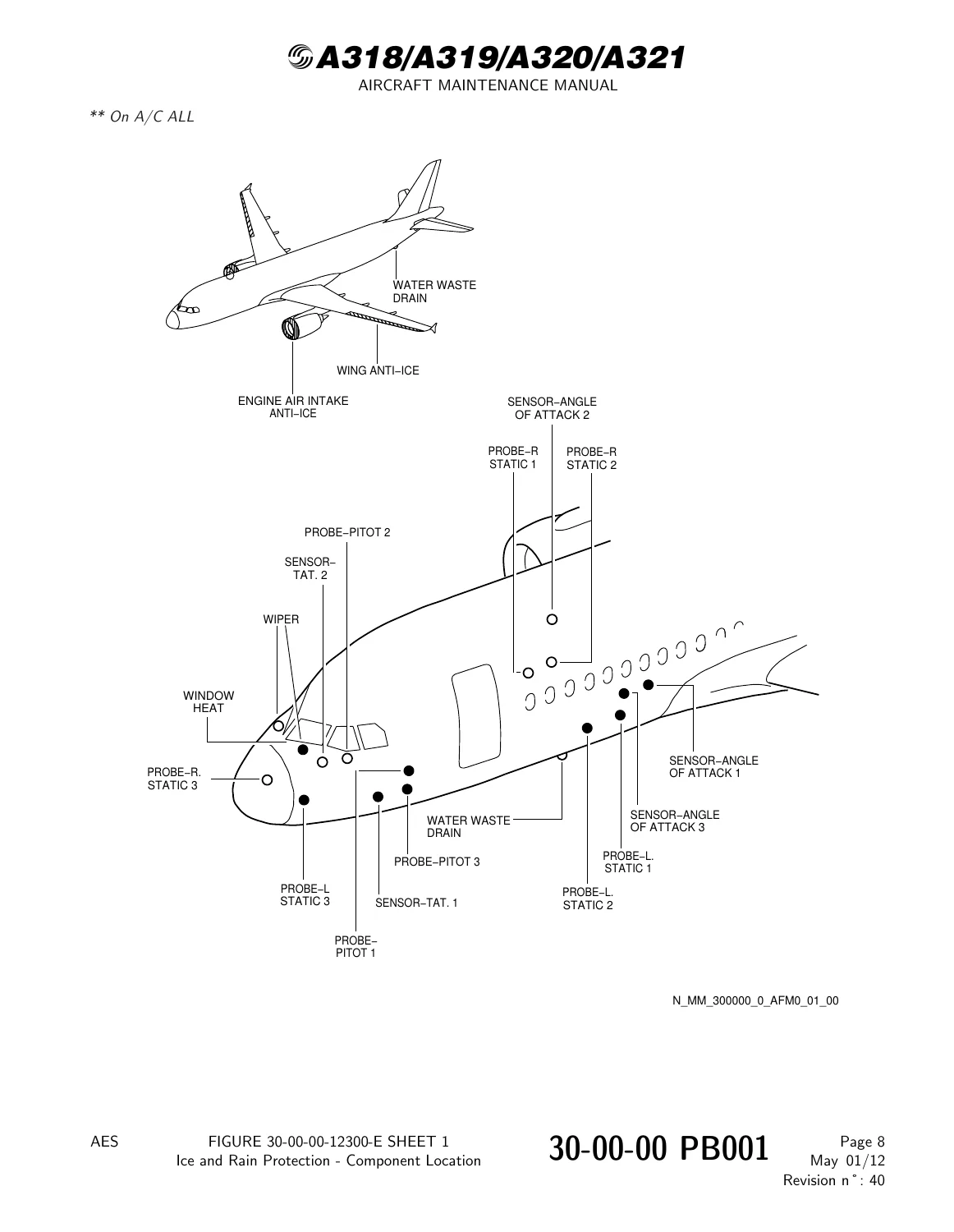
Airbus A318 A319 A320 A321 Aircraft Maintenance Manual - Chapter 30 Ice and Rain Protection — PDF page 19 preview
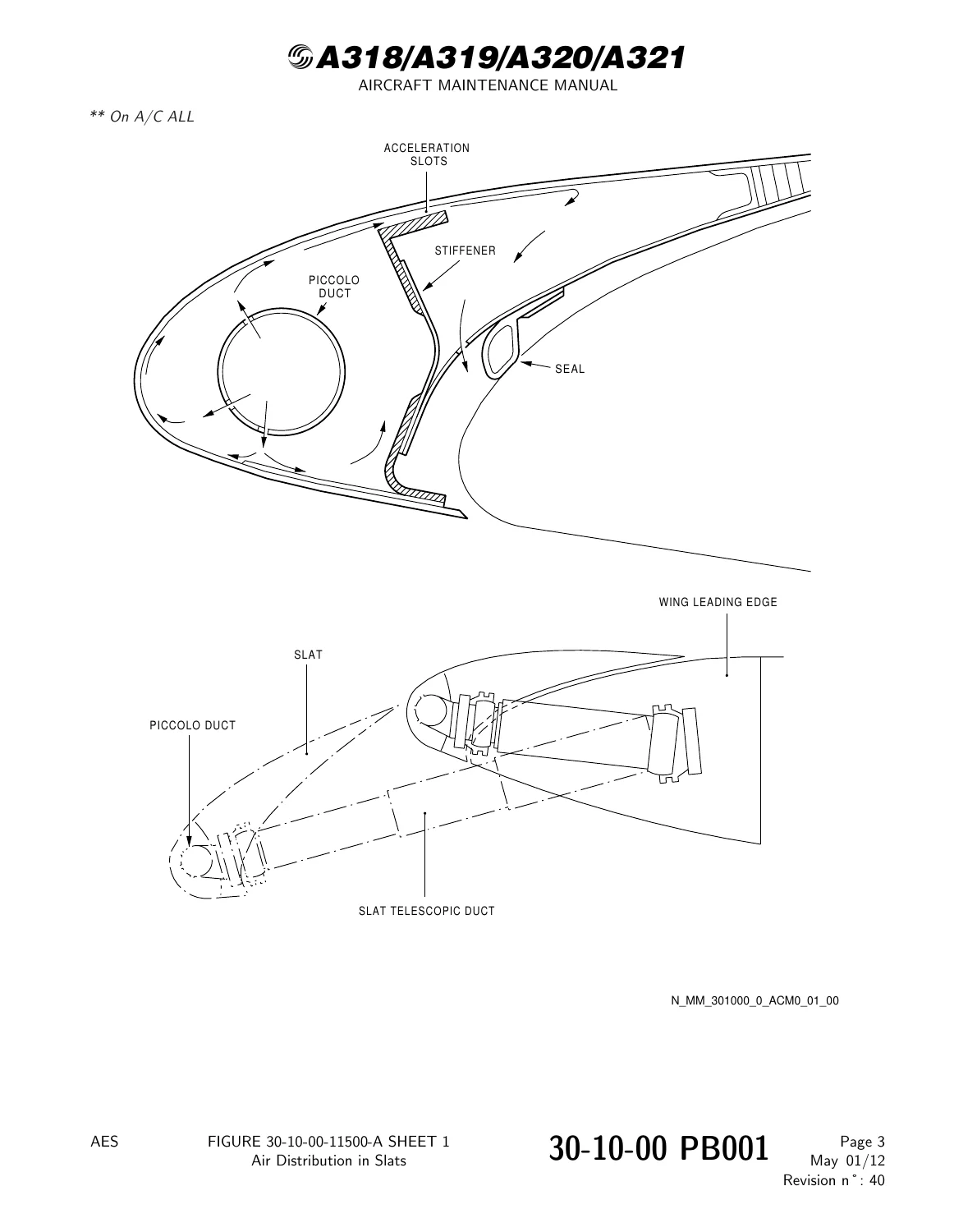
Airbus A318 A319 A320 A321 Aircraft Maintenance Manual - Chapter 30 Ice and Rain Protection — PDF page 37 preview

Chapters & Sections Covered

  • 30-00-00 Ice and Rain Protection – General: Overall system description and operation, general component layout, wing and engine anti-ice schematics, probe heating distribution, window heat schematics and glass cross-sections, drain mast locations, visual ice detection indicators, and complete AC/DC electrical bus power distribution diagrams.
  • 30-10-00 Airfoil: Aerodynamic surface protection principles, thermal anti-icing delivery via engine bleed air, and internal hot air distribution across wing leading edge slats.
  • 30-11-00 Wing Ice Protection: Full description and operation of LH and RH slat 3, 4, and 5 thermal protection, pneumatic supply downstream of precooler, cockpit overhead panel 25VU controls, warning logic, Electronic Centralized Aircraft Monitoring (ECAM) indications, and Multipurpose Control and Display Unit (MCDU) BITE displays.
  • 30-11-00 Deactivation / Reactivation & Testing: MMEL Task 30-11-01 procedures to lock wing anti-ice control valves in CLOSED or OPEN positions, fault light deactivation/reactivation, 30-second ground operational testing, and pneumatic supply duct leak checks using Ground Air Power Carts (GAPC).
  • 30-11-41 Duct – Telescopic: Removal and installation of leading-edge telescopic ducts at track 7/rib 13, including three-stage sliding sleeve inspection, link rod connections, torque values, and slat extension/retraction verification tests.
  • 30-11-42 Duct – Anti-Ice: Detailed disassembly, seal replacement, insulation muff safety wiring, bonding strap continuity, and reassembly of fixed leading-edge anti-ice ducts across wing ribs 9 through 13.
  • 30-11-51 Valve – Wing Anti-Ice Control: Removal, bench check, and installation procedures for wing anti-ice control valves 9DL and 10DL, actuator coupling alignments, and scheduled replacement of internal pneumatic valve filters (Task 30-11-51-960-001-A).
  • 30-21-00 Engine Air Intake Ice Protection: High-pressure compressor 7th-stage bleed air routing, solenoid-operated nacelle anti-ice (NAI) butterfly shut-off valves, upstream motive pressure limits, flight phase ECAM warning inhibition logic, and manual locking override procedures.
  • 30-21-00 Engine Anti-Ice Maintenance Tasks: MMEL deactivation and reactivation tasks for engine anti-ice valves locked in OPEN or CLOSED configurations, fault warning operational checks, partial power assurance testing, and NAI valve muscle pressure testing with test set 98D36003000003.
  • 30-21-49 Ducts – Anti-Ice: Removal, installation, and rigging of engine intake anti-ice ducts No. 1 through No. 5, pylon anti-ice duct stop plate modifications, and TAI interbulkhead spray ring assembly procedures.
  • 30-31-00 Probe Ice Protection: Independent electrical heating networks for CAPT, F/O, and STBY channels covering pitot tubes, static ports, Angle of Attack (AOA/alpha) sensors, and Total Air Temperature (TAT) probes, accompanied by Probe Heat Computer (PHC) functional tests and insulation resistance testing.
  • 30-42-00 Windshield Anti-Icing and Defogging: Electrical heating film and resistance wire controls for cockpit front windshields, fixed side windows, and sliding windows, regulated between 35°C and 42°C by Window Heat Computers (WHC).
  • 30-45-00 Windshield Rain Protection: Dual independent two-speed windshield wiper systems (95 cycles/min slow, 140 cycles/min fast) with parked aerodynamic stowage, rain repellent fluid can servicing, solenoid valves, and spray nozzle adjustments.
  • 30-71-00 Drain Mast Ice Protection: Dual-power heated waste-water drain masts (4DU and 14DU) operating at 18.72 W on the ground and 313.6 W in flight, temperature sensors, and electronic control units.
  • 30-72-00 & 30-73-00 Potable Water Ice Protection & Panel Heating: Heated service panels, fill/drain nipples (11DV), line heater elements, and BITE test routines.
  • 30-81-00 Ice Detection: Visual cockpit center windshield post icing indicator installation, inspection, and LED illumination replacement.

Together, these organized chapters give aircraft engineers, line technicians, and airframe mechanics an end-to-end technical dossier. Every subsystem is documented from theory of operation and system schematics down to circuit breaker references on panels 49VU, 121VU, and 122VU, specific mechanical torque limits, expendable seal part numbers, and ground safety lockouts.

Pneumatic Wing Anti-Ice Operation & Component Servicing

The pneumatic wing ice protection system documented in this Airbus A318 A319 A320 A321 Aircraft Maintenance Manual – Chapter 30 Ice and Rain Protection utilizes engine bleed air extracted downstream of the precooler. Hot compressed air is delivered along the wing fixed leading edge to thermal anti-icing piccolo tubes inside slats 3, 4, and 5. Technicians will find complete functional descriptions of the electro-pneumatic wing anti-ice valves (FIN 9DL on the left wing and 10DL on the right wing), which are spring-loaded to the safe closed position in the event of electrical power interruption. The manual outlines the precise regulating parameters: valves maintain downstream air outlet pressure at 1.55 bar (22.48 psi) ± 0.17 bar (2.46 psi), with internal pressure switches triggering ECAM fault warnings if supply pressure drops below 0.9 bar (13.05 psi) or exceeds 2.2 bar (31.9 psi).

Detailed step-by-step procedures outline how to safely remove, inspect, and reinstall wing anti-ice control valves, including coupling torque specifications of 0.39 to 0.51 m.daN (34.5 to 45.1 lbf.in), locating pin engagements, and scheduled replacement of the integrated anti-ice valve filter (Material No. 19-010 lockwire and replacement O-rings). Furthermore, the maintenance text covers the complete maintenance sequence for the track 7 telescopic duct assemblies, guiding mechanics through extension, link rod torquing (0.6 to 0.9 m.daN / 53.1 to 79.6 lbf.in), alignment pins, and operational slat travel checks.

Complete PDF Bookmark Tree

Complete Bookmarks

The complete bookmarks in the “Airbus A318 A319 A320 A321 Aircraft Maintenance Manual – Chapter 30 Ice and Rain Protection” are as follows:

Manual Front Matter
Chapter 05 – TIME LIMITS – MAINTENANCE CHECKS
Chapter 06 – DIMENSIONS AND AREAS
Chapter 07 – LIFTING AND SHORING
Chapter 08 – LEVELING AND WEIGHING
Chapter 09 – TOWING AND TAXIING
Chapter 10 – PARKING, MOORING, STORAGE & RETURN TO SERVICE
Chapter 11 – PLACARDS AND MARKINGS
Chapter 12 – SERVICING
Chapter 20 – STANDARD PRACTICES – AIRFRAME
Chapter 21 – AIR CONDITIONING
Chapter 22 – AUTO FLIGHT
Chapter 23 – COMMUNICATIONS
Chapter 24 – ELECTRICAL POWER
Chapter 25 – EQUIPMENT/FURNISHINGS
Chapter 26 – FIRE PROTECTION
Chapter 27 – FLIGHT CONTROLS
Chapter 28 – FUEL
Chapter 29 – HYDRAULIC POWER
Chapter 30 – ICE AND RAIN PROTECTIONp. 1
Table of Contentsp. 1
30-00 – ICE AND RAIN PROTECTION – GENERALp. 11
30-00-00 – ICE AND RAIN PROTECTION – GENERALp. 11
30-00-00 PB 001 CONF 00 – ICE AND RAIN PROTECTION – GENERAL – DESCRIPTION AND OPERATIONp. 11
Generalp. 11
Component Locationp. 12
System Descriptionp. 13
Power Suppliesp. 17
Figure 30-00-00-12300-E – Ice and Rain Protection – Component Locationp. 18
Figure 30-00-00-13800-A – Wing Ice Protectionp. 19
Figure 30-00-00-13900-A – Wing Ice Protection – Controls and Indicationp. 20
Figure 30-00-00-14400-B – Engine Anti-ice – Schematicp. 21
Figure 30-00-00-14500-A – Engine Anti-ice – Controls and Indicationp. 22
Figure 30-00-00-15000-A – Probe Ice Protection – Schematicp. 23
Figure 30-00-00-15100-A – Pitot and Static Probes Heatingp. 24
Figure 30-00-00-15200-A – Alpha and TAT Probes Heatingp. 25
Figure 30-00-00-15300-A – Probe Ice Protection – Control Locationp. 26
Figure 30-00-00-15700-A – Window Heat – Schematicp. 27
Figure 30-00-00-15800-A – Windows – Typical Cross-sectionp. 28
Figure 30-00-00-16400-A – Window Heat – Control Locationp. 29
Figure 30-00-00-17400-A – Drain Mast Locationp. 30
Figure 30-00-00-17500-B – Windshield Rain Removalp. 31
Figure 30-00-00-18000-B – Ice Detection – Location and Detailp. 32
Figure 30-00-00-19200-H – Ice and Rain Protection – Power Suppliesp. 33
30-10 – AIRFOILp. 35
30-10-00 – AIRFOILp. 35
30-10-00 PB 001 CONF 00 – AIRFOIL – DESCRIPTION AND OPERATIONp. 35
Generalp. 35
Figure 30-10-00-11400-A – Airfoil Anti-icingp. 36
Figure 30-10-00-11500-A – Air Distribution in Slatsp. 37
30-11 – WING ICE PROTECTIONp. 38
30-11-00 – WING ICE PROTECTIONp. 38
30-11-00 PB 001 CONF 00 – WING ICE PROTECTION – DESCRIPTION AND OPERATIONp. 38
Generalp. 38
Component Locationp. 39
System Descriptionp. 40
Power Supplyp. 41
Interfacesp. 42
Component Descriptionp. 43
Operation/Control and Indicatingp. 45
BITE Testp. 48
Figure 30-11-00-12400-A – Wing Ice Protection – Component Locationp. 49
Figure 30-11-00-12500-A – Wing Ice Protection – Panel Locationp. 50
Figure 30-11-00-14300-A – Air Distribution in Slatsp. 51
Figure 30-11-00-15500-A – Electrical Control System – Schematicp. 52
Figure 30-11-00-16800-A – Wing Anti-icing – Block Diagramp. 54
Figure 30-11-00-18400-C – Wing Anti-Ice Control Valve – Component Locationp. 55
Figure 30-11-00-18500-D – Wing Anti-Ice Control Valve – Schematic Operationp. 56
Figure 30-11-00-19200-B – Telescopic Duct – Component Locationp. 57
Figure 30-11-00-21700-A – Warning Logicp. 58
Figure 30-11-00-23900-A – MCDU System Displaysp. 59
30-11-00 PB 401 CONF 00 – WING ICE PROTECTION – DEACTIVATION/REACTIVATIONp. 62
30-11-00-040-001-A – Deactivation of the Wing Anti-Ice Control Valve to the CLOSED positionp. 62
Figure 30-11-00-991-00400-F – Wing Anti-Ice Control Valve – Component Locationp. 66
30-11-00-440-001-A – Reactivation of the Wing Anti Ice Control Valve from the CLOSED positionp. 67
30-11-00-040-004-A – Deactivation of the RH Wing Anti-Ice Control Valve to the OPEN positionp. 71
30-11-00-440-004-A – Reactivation of the RH Wing Anti-Ice Control Valve from the OPEN positionp. 75
30-11-00-040-002-A – Wing Anti Ice Fault LT – Valve Deactivationp. 79
30-11-00-440-003-A – Reactivation of the Wing Anti Ice Fault LTp. 81
30-11-00 PB 501 CONF 00 – WING ICE PROTECTION – ADJUSTMENT/TESTp. 83
30-11-00-710-001-A – Operational Test of the Wing Ice-Protection Systemp. 83
Figure 30-11-00-991-00100-A – Wing-Ice Protection – Indicationsp. 87
30-11-00-790-001-A – Leak Test of the Wing Anti-Ice Ductsp. 88
Figure 30-11-00-991-00600-C – Wing Anti-Ice Control Valve – Location and Detailp. 92
30-11-41 – DUCT – TELESCOPICp. 93
30-11-41 PB 401 CONF 00 – DUCT – TELESCOPIC – REMOVAL/INSTALLATIONp. 93
30-11-41-000-001-A – Removal of the Telescopic Ductp. 93
Figure 30-11-41-991-00100-B – Telescopic Ductp. 96
30-11-41-400-001-A – Installation of the Telescopic Ductp. 98
30-11-42 – DUCT – ANTI-ICEp. 102
30-11-42 PB 401 CONF 00 – DUCT – ANTI-ICE – REMOVAL/INSTALLATIONp. 102
30-11-42-000-001-A – Removal of the Anti-Ice Ductp. 102
Figure 30-11-42-991-00100-B – Anti-ice Duct – Ribs 9, 10 and 11p. 107
Figure 30-11-42-991-00200-B – Anti-ice Duct – Ribs 9, 10 and 11p. 108
Figure 30-11-42-991-00300-B – Anti-Ice Duct – Ribs 11, 12 and 13p. 109
30-11-42-400-001-A – Installation of the Anti-Ice Ductp. 110
30-11-51 – VALVE – WING ANTI ICE CONTROLp. 116
30-11-51 PB 401 CONF 00 – VALVE – WING ANTI ICE CONTROL – REMOVAL/INSTALLATIONp. 116
30-11-51-000-001-A – Removal of the Wing Anti-Ice Control Valvep. 116
Figure 30-11-51-991-00100-C – Wing Anti-Ice Control Valve – Location and Detailp. 118
30-11-51-400-001-A – Installation of the Wing Anti-Ice Control Valvep. 119
30-11-51-000-002-A – Removal of the Anti-Ice Valve Filterp. 123
Figure 30-11-51-991-00200-D – Anti-Ice Control Valve Filterp. 125
30-11-51-400-002-A – Installation of the Anti-Ice Valve Filterp. 126
30-11-51-960-001-A – Replacement of the Wing Anti-Ice Valve Filterp. 129
30-21 – ENGINE AIR INTAKE ICE PROTECTIONp. 132
30-21-00 – ENGINE AIR INTAKE ICE PROTECTIONp. 132
30-21-00 PB 001 CONF 13 – ENGINE AIR INTAKE ICE PROTECTION – DESCRIPTION AND OPERATIONp. 132
Generalp. 132
Component Locationp. 133
System Descriptionp. 134
Power Supplyp. 135
Interfacep. 136
Component Descriptionp. 137
Operation/Control and Indicatingp. 138
Figure 30-21-00-11200-A – Ice Protection of the Engine Air Intakes – Flow Diagramp. 140
Figure 30-21-00-12400-A – Ice Protection of the Engine Air Intakes – Component Locationp. 141
Figure 30-21-00-12500-B – Ice Protection of the Engine Air Intakes – Controlsp. 142
Figure 30-21-00-12600-A – Ice Protection of the Engine Air Intakes – Indications on Upper ECAM Display Unitp. 143
Figure 30-21-00-13800-A – Ice Protection of the Engine Air Intakes – Descriptionp. 144
Figure 30-21-00-19000-A – Anti Ice Valve of the Engine Air Intake – General Viewp. 145
Figure 30-21-00-19100-A – Anti Ice Valve of the Engine Air Intake – Schematicp. 146
Figure 30-21-00-19200-A – Anti Ice Access Panelp. 147
Figure 30-21-00-21000-A – Anti Ice Valve of the Engine Air Intake Not Closedp. 148
Figure 30-21-00-21100-A – Anti Ice Valve of the Engine Air Intake Not Openp. 149
30-21-00 PB 401 CONF 13 – ENGINE AIR INTAKE ICE PROTECTION – DEACTIVATION/REACTIVATIONp. 150
30-21-00-040-010-C – Deactivation of the Engine Anti-Ice Valve in the OPEN Positionp. 150
Figure 30-21-00-991-15000-B – Engine Air Intake Anti Ice Valvep. 152
30-21-00-040-010-C-01 – DELETEDp. 153
30-21-00-440-010-C – Reactivation of the Engine Anti-Ice Valve from the OPEN Positionp. 154
30-21-00-040-020-C – Deactivation of the Engine Anti-Ice Valve in the CLOSED Positionp. 156
30-21-00-440-020-B – Reactivation of the Engine Anti-Ice Valve from the CLOSED Positionp. 158
30-21-00-440-010-C-01 – DELETEDp. 160
30-21-00-040-020-A – DELETEDp. 161
30-21-00-440-020-A – DELETEDp. 162
30-21-00 PB 501 CONF 00 – ENGINE AIR INTAKE ICE PROTECTION – ADJUSTMENT/TESTp. 163
30-21-00-710-001-A – Operational Test of the Anti Ice System Fault Warningp. 163
30-21-00-710-002-A – Operational Test of the Engine Air Intake Ice Protection (with the Engines in operation)p. 166
30-21-00-710-003-A – Operational Test of the NAI Valvep. 168
Figure 30-21-00-991-00100-A – Location of the Muscle Pressure Hosep. 171
30-21-49 – DUCTS – ANTI ICEp. 172
30-21-49 PB 401 CONF 13 – DUCTS – ANTI ICE – REMOVAL/INSTALLATIONp. 172
30-21-49-000-010-B – Removal of the Anti-ice Duct No. 1p. 172
Figure 30-21-49-991-15000-B – Anti-ice Ductsp. 174
30-21-49-400-010-B – Installation of the Anti-ice Duct No. 1p. 175
30-21-49-000-011-B – Removal of the Anti-ice Duct No. 2p. 178
30-21-49-400-011-B – Installation of the Anti-ice Duct No. 2p. 180
30-21-49-000-012-B – Removal of the Anti-ice Duct No. 3p. 183
30-21-49-400-012-B – Installation of the Anti-ice Duct No. 3p. 185
30-21-49-000-013-B – Removal of the Anti-ice Duct No. 4p. 188
30-21-49-400-013-B – Installation of the Anti-ice Duct No. 4p. 190
30-21-49-000-014-B – Removal of the Anti-ice Duct No. 5p. 193
30-21-49-400-014-B – Installation of the Anti-ice Duct No. 5p. 195
30-21-49-000-042-A – Removal of the Pylon Anti-ice Ductp. 198
Figure 30-21-49-991-90200-B – Pylon Anti-ice Ductp. 199
30-21-49-400-042-A – Installation of the Pylon Anti-ice Ductp. 201
30-21-49-000-015-A – Removal of the Anti-Ice Interbulkhead Systemp. 203
Figure 30-21-49-991-16000-B – Anti-Ice Interbulkhead Systemp. 205
30-21-49-400-015-A – Installation of the Anti-Ice Interbulkhead Systemp. 206
30-21-49-820-010-A – Modification of the Pylon Anti-Ice Ductp. 209
30-21-49 PB 501 CONF 13 – DUCTS – ANTI ICE – ADJUSTMENT/TESTp. 210
30-21-49-820-001-A – Rig the Anti-ice Ductsp. 210
Figure 30-21-49-991-15400-A – Anti-Ice Ductsp. 215
30-21-49-790-010-A – Leak Test of the Inlet Cowl Anti-Ice Supply Ducts with the Engine in Operationp. 217
30-21-49 PB 601 CONF 13 – DUCTS – ANTI ICE – INSPECTION/CHECKp. 221
30-21-49-200-010-B – Detailed Visual Inspection of the Inlet Cowl Anti-Ice Supply Ducts and Associated Hardware in the Core Compartmentp. 221
Figure 30-21-49-991-15100-A – Anti-Ice Ductsp. 227
30-21-49-200-011-A – General Check of the Anti-Ice Ductsp. 230
Figure 30-21-49-991-15200-A – Anti-Ice Ductsp. 233
30-21-49-200-013-B – Detailed Check of the Anti-Ice Interbulkhead System with Component Removalp. 235
Figure 30-21-49-991-15700-B – Anti-Ice Interbulkhead Systemp. 241
30-21-51 – VALVE – ENGINE AIR INTAKE ANTI-ICEp. 245
30-21-51 PB 401 CONF 13 – ANTI ICE VALVE – ENGINE AIR INTAKE – REMOVAL/INSTALLATIONp. 245
30-21-51-000-010-B – Removal of the Engine Air Intake Anti-ice Valvep. 245
Figure 30-21-51-991-15000-B – Anti-ice Valvep. 247
30-21-51-400-010-B – Installation of the Engine Air Intake Anti-ice Valvep. 249
30-21-51 PB 601 CONF 13 – ANTI ICE VALVE – ENGINE AIR INTAKE – INSPECTION/CHECKp. 253
30-21-51-210-041-A – Inspection/Check of the Seal of the Engine Air-Intake Anti-Ice Valvep. 253
30-31 – PROBE ICE PROTECTIONp. 256
30-31-00 – PROBE ICE PROTECTIONp. 256
30-31-00 PB 001 CONF 00 – PROBE ICE PROTECTION – DESCRIPTION AND OPERATIONp. 256
Generalp. 256
Component Locationp. 257
System Descriptionp. 258
Power Supplyp. 259
Interfacep. 260
Component Descriptionp. 261
Operation/Control and Indicatingp. 263
BITE Testp. 264
Figure 30-31-00-12400-A – Probe Ice Protection – Component Locationp. 265
Figure 30-31-00-14100-A – Probe Ice Protection-Schematicp. 266
Figure 30-31-00-15300-B – Ice Protection of Probes 1 – Schematicp. 267
Figure 30-31-00-15400-B – Ice Protection of Probes 2 – Schematicp. 268
Figure 30-31-00-15500-B – Ice Protection of Probes 3 – Schematicp. 269
Figure 30-31-00-18500-B – Probe Ice Protection – Pitot Probep. 270
Figure 30-31-00-18600-A – Probe Ice Protection – Static Probep. 271
Figure 30-31-00-18700-A – Probe Ice Protection – Angle of Attack Sensorp. 272
Figure 30-31-00-18800-A – Probe Ice Protection – TAT Sensorp. 273
Figure 30-31-00-20300-A – Fault of Pitot Probes 1p. 274
Figure 30-31-00-20400-A – Fault of Pitot Probes 2p. 275
Figure 30-31-00-20500-A – Fault of Pitot Probes 3p. 276
Figure 30-31-00-20600-A – Fault of Probes 1 (2, 3) Heatp. 277
30-31-00 PB 401 CONF 00 – PROBE ICE PROTECTION – DEACTIVATION/REACTIVATIONp. 278
30-31-00-040-001-A – Check of the Operation of the Probe Heating Channelp. 278
30-31-00-440-001-A – DELETEDp. 282
30-31-00-040-002-A – Deactivation of the Heating of the Pitot Probesp. 283
30-31-00-440-002-A – Reactivation of the Heating of the Pitot Probesp. 292
30-31-00-040-003-A – Deactivation of the Heating of the Static Probesp. 293
30-31-00-440-003-A – Reactivation of the Heating of the Static Probesp. 302
30-31-00-040-004-A – Deactivation of the Heating of the Angle of Attack Sensorsp. 303
30-31-00-440-004-A – Reactivation of the Heating of the Angle of Attack Sensorsp. 312
30-31-00-040-005-A – Check of the ADR, CAPT (F/O, STBY) Probe Heaters and ECAM Warning Operationp. 313
30-31-00-440-005-A – Reactivation of the Probe Heat Computer (PHC)p. 322
30-31-00 PB 501 CONF 00 – PROBE ICE PROTECTION – ADJUSTMENT/TESTp. 323
30-31-00-710-001-A – Operational Test of the Probe Ice Protectionp. 323
30-31-00-710-002-A – Operational Test to Read the CLASS 3 FAULTSp. 325
30-31-00-710-007-A – Functional Test of the Heating of the Angle of Attack Sensorp. 327
Figure 30-31-00-991-00100-A – AOA Sensor Tool Connectionp. 334
30-31-00-720-001-A – Functional Test of the Insulation Resistance of the Pitot Probe Heaterp. 335
Figure 30-31-00-991-00200-A – Pitot Probep. 338
30-31-34 – COMPUTER – PROBE HEAT (PHC)p. 339
30-31-34 PB 401 CONF 00 – COMPUTER – PROBE HEAT (PHC) – REMOVAL/INSTALLATIONp. 339
30-31-34-000-002-A – Removal of the Probe Heat Computer (PHC)p. 339
Figure 30-31-34-991-00200-A – Probe Heat Computer (PHC)p. 341
30-31-34-400-002-A – Installation of the Probe Heat Computer (PHC)p. 342
30-42 – WINDSHIELD ANTI-ICING AND DEFOGGINGp. 345
30-42-00 – WINDSHIELD ANTI-ICING AND DEFOGGINGp. 345
30-42-00 PB 001 CONF 00 – WINDSHIELD ANTI-ICING AND DEFOGGING – DESCRIPTION AND OPERATIONp. 345
Generalp. 345
Component Locationp. 346
System Descriptionp. 347
Power Supplyp. 348
Interfacep. 349
Component Descriptionp. 350
Operation/Control and Indicatingp. 351
BITE Testp. 352
Figure 30-42-00-12400-B – Windshield Anti-icing and Defogging – Control Locationp. 353
Figure 30-42-00-12500-A – Windshield Anti-icing and Defogging – WHC Locationp. 354
Figure 30-42-00-13700-A – Windshield Anti-icing and Defogging – Schematicp. 355
Figure 30-42-00-14900-B – Anti-icing and Defogging – L Windshield and Windows – Schematicp. 356
Figure 30-42-00-15000-B – Anti-icing and Defogging – R Windshield and Windows – Schematicp. 357
Figure 30-42-00-17800-B – Windshield Anti-icing and Defogging Typical Section of Windshieldp. 358
Figure 30-42-00-17900-A – Windshield Anti-icing and Defogging Temperature Sensor Characteristics (Windshield)p. 359
Figure 30-42-00-18100-B – Composition of Sliding Windowp. 360
Figure 30-42-00-18200-B – Composition of Fixed Windowp. 361
Figure 30-42-00-18300-A – Window Temperaturep. 362
Figure 30-42-00-18700-A – Windshield Anti-icing and Defogging – WHCp. 363
Figure 30-42-00-20100-A – Windshield Anti-icing and Defogging – Schematicp. 364
Figure 30-42-00-20500-A – L(R) Windshield Faultp. 365
Figure 30-42-00-20600-A – L(R) Window Faultp. 366
Figure 30-42-00-20700-A – L and R Windshield Faultp. 367
Figure 30-42-00-21100-B – Anti-icing and Defogging of L Windshield and Windows – Schematicp. 368
Figure 30-42-00-21200-B – Anti-icing and Defogging of R Windshield and Windows – Schematicp. 369
30-42-00 PB 401 CONF 00 – WINDSHIELD ANTI-ICING AND DEFOGGING – DEACTIVATION/REACTIVATIONp. 370
30-42-00-040-001-A – Deactivation of the Window Heat Computer (WHC)p. 370
30-42-00-440-001-A – Reactivation of the Window Heat Computer (WHC)p. 373
30-42-00 PB 501 CONF 00 – WINDSHIELD ANTI-ICING AND DEFOGGING – ADJUSTMENT/TESTp. 375
30-42-00-710-001-A – Operational Test of the Windshield Anti-Icing and Defoggingp. 375
30-42-00-710-002-A – Operational Test to Read the CLASS 3 FAULTS.p. 377
30-42-34 – COMPUTER – WINDOW HEAT (WHC)p. 379
30-42-34 PB 401 CONF 00 – COMPUTER – WINDOW HEAT (WHC) – REMOVAL/INSTALLATIONp. 379
30-42-34-000-001-A – Removal of the Window Heat Computer (WHC)p. 379
Figure 30-42-34-991-00100-A – Window Heat Computer (WHC)p. 381
30-42-34-400-001-A – Installation of the Window Heat Computer (WHC)p. 382
30-45 – WINDSHIELD RAIN PROTECTIONp. 384
30-45-00 – WINDSHIELD RAIN PROTECTIONp. 384
30-45-00 PB 001 CONF 00 – WINDSHIELD RAIN PROTECTION – DESCRIPTION AND OPERATIONp. 384
Generalp. 384
Component Locationp. 385
System Descriptionp. 386
Power Supplyp. 388
Interfacesp. 389
Component Descriptionp. 390
Figure 30-45-00-13400-A – Wiper System – Controls Locationp. 394
Figure 30-45-00-13500-A – Wiper System – Componentp. 395
Figure 30-45-00-13600-B – Wiper System – Component Locationp. 396
Figure 30-45-00-13700-A – Rain Repellent System – Control Locationp. 397
Figure 30-45-00-13800-A – Rain Repellent System – General Viewp. 398
Figure 30-45-00-13900-B – Rain Repellent System – Component Locationp. 399
Figure 30-45-00-14000-B – Wiper System – Component Locationp. 400
Figure 30-45-00-17000-A – Wiper System – Schematicp. 401
Figure 30-45-00-19500-A – Wiper Motor Converterp. 402
Figure 30-45-00-19600-A – Wiper System – Sweeping Areap. 403
Figure 30-45-00-19800-A – Adjustment of the Pressure of the Arm on the Windshieldp. 404
Figure 30-45-00-20300-A – Rain Repellent System-Schematicp. 405
30-45-00 PB 301 CONF 00 – WINDSHIELD RAIN PROTECTION – SERVICINGp. 406
30-45-00-600-001-A – Servicing of the Rain Repellent Fluid Canp. 406
Figure 30-45-00-991-00300-B – Rain Repellent Fluid Canp. 410
30-45-00-600-002-A-01 – Servicing of the Rain Repellent Systemp. 411
Figure 30-45-00-991-00500-B – Rain Repellent Systemp. 416
30-45-00 PB 401 CONF 00 – WINDSHIELD RAIN PROTECTION – DEACTIVATION/REACTIVATIONp. 417
30-45-00-040-002-A – Deactivation of the Rain Repellent Systemp. 417
Figure 30-45-00-991-00600-C – Rain Repellent Systemp. 422
Figure 30-45-00-991-00700-A – "RAIN REPELLENT DEACTIVATED" Placardsp. 423
30-45-00-440-002-A – Reactivation of the Rain Repellent Systemp. 424
30-45-00-040-003-A – Deactivation of the Windshield Wiperp. 428
30-45-00-440-003-A – Reactivation of the Windshield Wiperp. 429
30-45-00 PB 501 CONF 00 – WINDSHIELD RAIN PROTECTION – ADJUSTMENT/TESTp. 430
30-45-00-720-001-A – Functional Test of the Windshield Rain Protectionp. 430
30-45-00-720-002-A – Functional Test of the Rain Repellent Systemp. 433
Figure 30-45-00-991-01200-A – Rain Repellent Blowout Reservoirp. 438
30-45-00 PB 601 CONF 00 – WINDSHIELD RAIN PROTECTION – INSPECTION/CHECKp. 439
30-45-00-200-001-A – Inspection/Check of the Operation of the Windshield Wipers.p. 439
Figure 30-45-00-991-00100-A – Operation of the Windshield Wipersp. 441
30-45-41 – VALVE – RAIN REPELLENT SOLENOIDp. 442
30-45-41 PB 401 CONF 00 – VALVE – RAIN REPELLENT SOLENOID – REMOVAL/INSTALLATIONp. 442
30-45-41-000-001-A – Removal of the Rain-Repellent Solenoid Valvep. 442
Figure 30-45-41-991-00100-A – Rain-Repellent Solenoid Valvep. 445
30-45-41-400-001-A – Installation of the Rain-Repellent Solenoid Valvep. 446
30-45-43 – GAGE ASSY – RAIN REPELLENT FLUIDp. 450
30-45-43 PB 401 CONF 00 – GAGE ASSY – RAIN REPELLENT FLUID – REMOVAL/INSTALLATIONp. 450
30-45-43-000-001-A – Removal of the Rain-Repellent Fluid Gage Assyp. 450
Figure 30-45-43-991-00100-B – Rain-Repellent Fluid Gagep. 453
30-45-43-400-001-A – Installation of the Rain-Repellent Fluid Gage Assyp. 454
30-45-44 – NOZZLE – SPRAYp. 458
30-45-44 PB 401 CONF 00 – NOZZLE – SPRAY – REMOVAL/INSTALLATIONp. 458
30-45-44-000-001-A – Removal of the Spray Nozzlep. 458
Figure 30-45-44-991-00100-A – Spray Nozzlep. 460
30-45-44-400-001-A – Installation of the Spray Nozzlep. 461
Figure 30-45-44-991-00200-A – Position of the Spray Nozzle Slotp. 463
30-45-45 – RESERVOIR – RAIN REPELLENT BLOWOUTp. 464
30-45-45 PB 401 CONF 00 – RESERVOIR – RAIN REPELLENT BLOWOUT – REMOVAL/INSTALLATIONp. 464
30-45-45-000-001-A – Removal of the Check Valve and of the Rain Repellent Blowout Reservoirp. 464
Figure 30-45-45-991-00100-A – Rain Repellent Blowout Reservoirp. 466
30-45-45-400-001-A – Installation of the Check Valve and of the Rain Repellent Blowout Reservoirp. 467
30-45-46 – CHECK VALVE – RAIN REPELLENTp. 470
30-45-46 PB 401 CONF 00 – CHECK VALVE – RAIN REPELLENT – REMOVAL/INSTALLATIONp. 470
30-45-46-000-001-A – Removal of the Rain-Repellent Check Valvep. 470
Figure 30-45-46-991-00100-A – Rain-Repellent Check Valvep. 473
30-45-46-400-001-A – Installation of the Rain-Repellent Check Valvep. 474
30-45-51 – MOTOR CONVERTER – WIPERp. 477
30-45-51 PB 401 CONF 00 – MOTOR CONVERTER – WIPER – REMOVAL/INSTALLATIONp. 477
30-45-51-000-001-A – Removal of the Wiper Motor Converterp. 477
Figure 30-45-51-991-00100-C – Wiper Motor Converterp. 479
30-45-51-400-001-A – Installation of the Wiper Motor Converterp. 480
30-45-52 – ARM – WIPERp. 483
30-45-52 PB 401 CONF 00 – ARM – WIPER – REMOVAL/INSTALLATIONp. 483
30-45-52-000-002-A – Removal of the Wiper Armp. 483
Figure 30-45-52-991-00100-B – Wiper Armp. 486
30-45-52-400-002-A – Installation of the Wiper Armp. 487
Figure 30-45-52-991-00200-A – Installation of Wiper Armp. 492
Figure 30-45-52-991-00300-A – Wiper Arm – Testp. 493
30-45-53 – BLADE – WIPERp. 494
30-45-53 PB 401 CONF 00 – BLADE – WIPER – REMOVAL/INSTALLATIONp. 494
30-45-53-000-001-A – Removal of the Wiper Bladep. 494
Figure 30-45-53-991-00100-A – Wiper Bladep. 496
30-45-53-400-001-A – Installation of the Wiper Bladep. 497
30-71 – DRAIN MAST ICE PROTECTIONp. 499
30-71-00 – DRAIN MAST ICE PROTECTIONp. 499
30-71-00 PB 001 CONF 00 – DRAIN MAST ICE PROTECTION – DESCRIPTION AND OPERATIONp. 499
Generalp. 499
Component Locationp. 500
System Descriptionp. 501
Operation/Control and Indicatingp. 503
Testp. 504
Figure 30-71-00-11200-A – Waste-Water Ice-Protection – Functional Diagramp. 505
Figure 30-71-00-12500-B – Waste-Water Ice-Protection – Component Locationp. 506
Figure 30-71-00-12500-D – Waste-Water Ice-Protection – Component Locationp. 507
Figure 30-71-00-12600-F – Waste Water Ice Protection – Component Locationp. 508
Figure 30-71-00-15600-B – Waste Water Ice Protection – Electrical Schematicp. 509
30-71-00 PB 401 CONF 00 – DRAIN MAST ICE PROTECTION – DEACTIVATION/REACTIVATIONp. 510
30-71-00-040-001-A – Deactivation of the Waste-Water Drain Mast Heating-Systemp. 510
Figure 30-71-00-991-00100-A – Potable Water Lavatory Shut of Valvep. 512
30-71-00-440-001-A – Reactivation of the Waste-Water Drain Mast Heating-Systemp. 513
30-71-00 PB 501 CONF 00 – WASTE WATER ICE PROTECTION – ADJUSTMENT/TESTp. 515
30-71-00-710-001-A – Operational Test of the Drainmast Ice Protectionp. 515
30-71-00-710-002-A – Operational Test of the Waste-Water Ice-Protection Heater-Elementsp. 518
30-71-17 – SENSOR – TEMPERATUREp. 520
30-71-17 PB 401 CONF 00 – SENSOR – TEMPERATURE – REMOVAL/INSTALLATIONp. 520
30-71-17-000-001-A – Removal of the Waste-Water De-icing Sensorp. 520
Figure 30-71-17-991-00100-A – Waste-Water De-icing Sensorp. 522
30-71-17-400-001-A – Installation of the Waste-Water De-icing Sensorp. 523
30-71-34 – CONTROL UNIT – WASTE WATER ICE PROTECTIONp. 525
30-71-34 PB 401 CONF 00 – CONTROL UNIT – WASTE WATER ICE PROTECTION – REMOVAL/INSTALLATIONp. 525
30-71-34-000-001-A – Removal of the Waste-Water Ice-Protection Control-Unitp. 525
Figure 30-71-34-991-00100-E – Control Unit 5DU/15DUp. 527
30-71-34-400-001-A – Installation of the Waste-Water Ice-Protection Control-Unitp. 528
30-71-51 – DRAIN MASTp. 531
30-71-51 PB 401 CONF 00 – DRAIN MAST – REMOVAL/INSTALLATIONp. 531
30-71-51-000-001-A – Removal of the Drain Mastp. 531
Figure 30-71-51-991-00100-B – Drain Mast 4DU/14DUp. 535
Figure 30-71-51-991-00100-D – Drain Mast 4DU/14DUp. 536
30-71-51-400-001-A – Installation of the Drain Mastp. 537
Figure 30-71-51-991-00400-A – Drain Mast – Heater Tube Assemblyp. 545
Figure 30-71-51-991-00400-B – Drain Mast – Heater Tube Assemblyp. 546
30-71-51 PB 601 CONF 00 – DRAIN MAST – INSPECTION/CHECKp. 547
30-71-51-200-001-A – Visual Inspection of the Drain Mastp. 547
Figure 30-71-51-991-00300-A – Visual Inspection of Drain Mast (4DU, 14DU and 24DU)p. 550
Figure 30-71-51-991-00300-B – Visual Inspection of Drain Mast (4DU, 14DU and 24DU)p. 551
30-71-53 – HEATER ELEMENTp. 552
30-71-53 PB 401 CONF 00 – HEATER ELEMENT – REMOVAL/INSTALLATIONp. 552
30-71-53-000-001-A – Removal of the Waste-Water De-icing Heater Elementsp. 552
Figure 30-71-53-991-00100-A – Heater Elementsp. 554
30-71-53-400-001-A – Installation of the Waste-Water De-icing Heater Elementsp. 555
30-72 – WATER SERVICING PANELS HEATINGp. 558
30-72-00 – WATER SERVICING PANELS HEATINGp. 558
30-72-00 PB 001 CONF 00 – WATER SERVICING PANELS HEATING – DESCRIPTION AND OPERATIONp. 558
Generalp. 558
Component Locationp. 559
System Descriptionp. 560
Power Supplyp. 561
Operation/Control and Indicatingp. 562
Figure 30-72-00-11400-B – Water Service Panels – Heatedp. 563
Figure 30-72-00-12700-E – Component Location – Heater/Thermostatp. 564
Figure 30-72-00-16800-E – Water Service Panels – Electrical Schematicp. 565
30-72-11 – THERMOSTAT – FILL/DRAIN/OVERFLOW NIPPLEp. 566
30-72-11 PB 401 CONF 00 – THERMOSTAT – FILL/DRAIN/OVERFLOW NIPPLE – REMOVAL/INSTALLATIONp. 566
30-72-11-000-001-A – Removal of the Thermostatp. 566
Figure 30-72-11-991-00100-B – Removal/Installation of Thermostat 12DVp. 568
30-72-11-400-001-A – Installation of the Thermostatp. 569
30-72-52 – NIPPLE – FILL/DRAIN/OVERFLOWp. 572
30-72-52 PB 401 CONF 00 – NIPPLE – FILL/DRAIN/OVERFLOW – REMOVAL/INSTALLATIONp. 572
30-72-52-000-001-A – Removal of the Heated Fill/Drain Nipple 11DV and/or Overflow Nipple 13DVp. 572
Figure 30-72-52-991-00100-B – Fill/Drain Nipple 11DVp. 574
30-72-52-400-001-A – Installation of the Heated Fill/Drain Nipple 11DV and/or Overflow Nipple 13DVp. 575
30-73 – POTABLE WATER ICE PROTECTIONp. 579
30-73-00 – POTABLE WATER ICE PROTECTIONp. 579
30-73-00 PB 001 CONF 00 – POTABLE WATER ICE PROTECTION – DESCRIPTION AND OPERATIONp. 579
Generalp. 579
Component Locationp. 580
System Descriptionp. 581
Power Supplyp. 582
Operation/Control and Indicatingp. 583
Figure 30-73-00-12300-Q – Potable Water Ice Protection – Component Locationp. 584
Figure 30-73-00-12500-A – Potable Water Ice Protection – Component Location.p. 585
Figure 30-73-00-15500-E – Potable Water Ice Protection – Electrical Schematic.p. 586
Figure 30-73-00-15500-F – Potable Water Ice Protection – Electrical Schematic.p. 587
30-73-00 PB 501 CONF 00 – POTABLE WATER ICE PROTECTION – ADJUSTMENT/TESTp. 588
30-73-00-740-001-A – BITE Test of the Potable Water Ice-Protectionp. 588
30-73-00-720-001-A – Functional Test of the Potable Water Ice-Protectionp. 590
30-73-17 – SENSORp. 593
30-73-17 PB 401 CONF 00 – SENSOR – REMOVAL/INSTALLATIONp. 593
30-73-17-000-001-A – Removal of the Potable-Water De-icing Sensorp. 593
Figure 30-73-17-991-00100-D – Potable-Water De-icing Sensorp. 595
30-73-17-400-001-A – Installation of the Potable-Water De-icing Sensorp. 596
30-73-34 – CONTROL UNIT – POTABLE WATER ICE PROTECTIONp. 598
30-73-34 PB 401 CONF 00 – CONTROL UNIT – POTABLE WATER ICE PROTECTION – REMOVAL/INSTALLATIONp. 598
30-73-34-000-001-A – Removal of the Potable and Waste Water Ice Protection Control Unitp. 598
Figure 30-73-34-991-00100-A – Control Unitp. 600
30-73-34-400-001-A – Installation of the Potable and Waste Water Ice Protection Control Unitp. 601
30-73-53 – HEATER ELEMENTp. 603
30-73-53 PB 401 CONF 00 – HEATER ELEMENT – REMOVAL/INSTALLATIONp. 603
30-73-53-000-001-A – Removal of the Potable-Water De-icing Heater Elementsp. 603
Figure 30-73-53-991-00100-A – Heater Elements Locationp. 605
Figure 30-73-53-991-01200-A – Heater Elementsp. 606
30-73-53-400-001-A – Installation of the Potable-Water De-icing Heater Elementsp. 608
30-81 – ICE DETECTIONp. 611
30-81-00 – ICE DETECTIONp. 611
30-81-00 PB 001 CONF 00 – ICE DETECTION – DESCRIPTION AND OPERATIONp. 611
Generalp. 611
Component Locationp. 612
System Descriptionp. 613
Power Supplyp. 614
Interfacep. 615
Component Descriptionp. 616
Operation/Control and Indicatingp. 617
Figure 30-81-00-12600-A – Lighted Icing Indicatorp. 618
Figure 30-81-00-12700-A – Lighted Icing Indicatorp. 619
Figure 30-81-00-15600-A – Lighted Icing Indicator – Power Supplyp. 620
Figure 30-81-00-18400-A – Lighted Icing Indicatorp. 621
30-81-21 – INDICATOR – VISUAL, ICINGp. 622
30-81-21 PB 401 CONF 01 – INDICATOR – LIGHTED, ICING – REMOVAL/INSTALLATIONp. 622
30-81-21-000-001-A – Removal of the Lighted Icing Indicatorp. 622
Figure 30-81-21-991-00200-A – Lighted Icing Indicatorp. 624
30-81-21-400-001-A – Installation of the Lighted Icing Indicatorp. 626
30-81-21-960-001-A – Replacement of the LED of the Lighted Icing Indicatorp. 629
30-81-21 PB 601 CONF 00 – INDICATOR – VISUAL, ICING – INSPECTION/CHECKp. 630
30-81-21-200-001-A – Inspection/Check of the Lighted Icing Indicatorp. 630
Chapter 31 – INDICATING/RECORDING SYSTEMS
Chapter 32 – LANDING GEAR
Chapter 33 – LIGHTS
Chapter 34 – NAVIGATION
Chapter 35 – OXYGEN
Chapter 36 – PNEUMATIC
Chapter 38 – WATER/WASTE
Chapter 46 – INFORMATION SYSTEMS
Chapter 49 – AIRBORNE AUXILIARY POWER
Chapter 51 – STANDARDS PRACTICES AND STRUCTURES
Chapter 52 – DOORS
Chapter 53 – FUSELAGE
Chapter 54 – NACELLES/PYLONS
Chapter 55 – STABILIZERS
Chapter 56 – WINDOWS
Chapter 57 – WINGS
Chapter 70 – (IAE) – STANDARD PRACTICES – ENGINE
Chapter 71 – (IAE) – POWER PLANT
Chapter 72 – (IAE) – ENGINE
Chapter 73 – (IAE) – ENGINE FUEL AND CONTROL
Chapter 74 – (IAE) – IGNITION
Chapter 75 – (IAE) – AIR
Chapter 76 – (IAE) – ENGINE CONTROLS
Chapter 77 – (IAE) – ENGINE INDICATING
Chapter 78 – (IAE) – EXHAUST
Chapter 79 – (IAE) – OIL
Chapter 80 – (IAE) – STARTING

MMEL Valve Deactivation & Ground Testing Standards

When unexpected valve malfunctions occur on the line, maintaining operational dispatch capability is paramount. This manual provides direct compliance procedures for Master Minimum Equipment List dispatch under ATA 30-11 and ATA 30-21. Mechanics are guided through deactivating and securing the wing anti-ice control valves 9DL and 10DL in the CLOSED position using the integrated manual locking pin, lockwire (0.8 mm stainless steel annealed), and mandatory cockpit placards. For right-hand wing valve 10DL, deactivation to the OPEN position is fully detailed, highlighting specific flight operation limitations and slat overheat precautions.

Similar MMEL procedures govern the nacelle anti-ice valves (FIN 4000DN) on engine air intakes, including mechanical manual override limits (maximum 50 lbf.in / 0.56 m.daN applied to the hexagonal shaft nut) and locking pin placement. In addition, the guide provides comprehensive instructions for the 30-second ground operational test of the wing anti-ice system, complete with relay timing checks (relay 4DL and 5DL) to prevent thermal damage to extended slats, as well as ground leak testing instructions utilizing external Ground Air Power Carts connected to the high-pressure receptacle on access panel 191DB.

Electrical Probe, Window Heat & Waste Water Heating Systems

Beyond pneumatic thermal systems, this manual provides detailed coverage of the high-amperage electrical de-icing networks managed by dedicated avionics computers. Technicians gain access to wiring and sensor diagrams for the Probe Heat Computers (PHC 1, 2, and 3), controlling 115V AC supplies to pitot probes, Angle of Attack sensors, and TAT sensors, alongside 28V DC power routed to static ports. Ground/flight detector logic, automatic probe heat startup upon first engine start, and ground temperature attenuation are fully mapped.

The flight deck windshield anti-icing and defogging chapter details the construction and heating circuits of front laminated glass (incorporating chemical-reinforced plies and continuous heating films) and side acrylic windows. Temperature regulation by the dual Window Heat Computers (WHC 1 and 2) is documented with sensor resistance charts holding temperatures between 35°C (95°F) and 42°C (107.6°F). Complete removal, installation, and inspection routines are also provided for two-speed windshield wiper motor converters, rain repellent solenoid valves, and fuselage waste-water drain masts (4DU and 14DU), ensuring total aircraft dispatch readiness in cold-weather and icing conditions.

Professional Technical Capability & Instant PDF Delivery

Carrying the correct OEM technical documentation is vital for ensuring aviation safety, structural integrity, and strict airworthiness compliance. The Airbus A318 A319 A320 A321 Aircraft Maintenance Manual – Chapter 30 Ice and Rain Protection equips licensed aircraft maintenance technicians, avionics specialists, base maintenance supervisors, and flight operations personnel with the precise instructions required to diagnose faults, replace line-replaceable units (LRUs), perform leak checks, and execute MMEL deactivations safely. Utilizing genuine maintenance specifications prevents accidental pneumatic duct blowouts, avoids expensive slat thermal deformation, and guarantees proper rigging of telescopic joints and flight control interlocks.

Delivered as an instant high-resolution PDF download immediately following purchase, this manual requires no waiting for physical media. It can be accessed on demanding ramp environments, line stations, or workshop tablets, laptops, and desktop computers, and is fully printable for inclusion in physical maintenance work orders and task sign-off packets.
Reviews

There are no reviews yet.

Be the first to review “Airbus A318 A319 A320 A321 Aircraft Maintenance Manual – Chapter 30 Ice and Rain Protection”

What Our Customers Say

★★★★★ Live reviews from customers
Loading customer reviews...
0
    0
    Your Cart
    Your cart is emptyReturn to Shop
    🛒
    Recently Purchased
    🕒 verified order