
Thales TopSeries i4000 LAN Airlines Boeing 767 Aircraft Maintenance Manual ATA 44-21-74 Rev 4
Original price was: $37.95.$21.95Current price is: $21.95.
Thales Avionics line-maintenance AMM for the TopSeries i4000 IFE system on LAN Airlines Boeing 767 aircraft, ATA 44-21-74 Revision 4 dated Feb 28/09.
Description
Thales TopSeries i4000 Line Maintenance Data for LAN Boeing 767 Cabins
The Thales TopSeries i4000 LAN Airlines Boeing 767 Aircraft Maintenance Manual ATA 44-21-74 Rev 4 is the Thales Avionics, Incorporated aircraft maintenance manual written for line maintenance of the TopSeries i4000 inflight entertainment system on the LAN Airlines Boeing 767 fleet listed in the document. It is organized to ATA iSpec2200 and is intended to supplement the Boeing 767 Aircraft Maintenance Manual; where the two documents conflict, the Boeing 767 AMM takes precedence. The title page of this copy carries a TRAINING USE ONLY watermark. Cabin layout in the configuration statement is 221 passengers: 30 Business Class seats and 191 Economy Class seats. Some aircraft were linefit at Boeing and others were retrofit by Thales; effectivity notes throughout the book separate those two groups.
File Details
- Manual type: Aircraft Maintenance Manual (ATA 44-21-74)
- Brand / system: Thales Avionics TopSeries i4000 Inflight Entertainment System
- Aircraft: LAN Airlines Boeing 767
- Document number: 44-21-74
- Revision: Revision 4, Feb 28/09 (Initial Issue Nov 30/05)
- Language: English
- Page count: 355
- File format: PDF
- Publisher: Thales Avionics, Incorporated, Aerospace Division, Irvine, California (CAGE 0LWJ2)
Aircraft Serials and Registrations Covered
The title page lists these Boeing 767 serial numbers: 25864, 25865, 26261, 26265, 26327, 26329, 27597, 27613, 27615, 28206, 29227, 29228, 29229, 34626, 34628, 34629, 35229, 35230, 35231, 35696, 35697, 35698, 36710, 36711, and 36712. The Linefit and Retrofit Tail Number Index maps those serials to registrations including CC-CBJ, CC-CDM, CC-CDP, CC-CEB, CC-CRG, CC-CRH, CC-CRV, CC-CZT, CC-CZU, CC-CZW, HC-CGZ, LV-BFD, LV-BMR, CC-CWF, CC-CWG, CC-CWH, CC-CWN, CC-CWV, CC-CWY, CC-CXC, CC-CXD, CC-CXE, CC-CXF, CC-CXG, and CC-CXH. Retrofit serials are 25864, 25865, 26261, 26265, 26327, 26329, 27597, 27613, 27615, 28206, 29227, 29228, and 29229. Linefit serials are 34626, 34628, 34629, 35229, 35230, 35231, 35696, 35697, 35698, 36710, 36711, and 36712.
What the i4000 Cabin Actually Contains
Passenger services described in the Thales TopSeries i4000 LAN Airlines Boeing 767 Aircraft Maintenance Manual ATA 44-21-74 Rev 4 include overhead video on eight monitors (one wall-mounted in Business Class and seven in Economy Class), in-seat video on Smart Video Display Units at every seat, and passenger-selectable audio through headsets at the Audio Jack Module. Business Class uses a 15.4-inch SVDU without touch screen; Economy Class uses an 8.9-inch touch-screen SVDU. Front-row displays are bulkhead mounted. Video and audio are selected with the Tethered Passenger Control Unit – Basic at each seat, or with the Economy Class touch screen. Noise-canceling features are integrated into the AJM at Business Class seats. Overhead video on retrofit aircraft uses cabin-wall 20-inch SVDUs; linefit aircraft use 15-inch SVDUs. Per LAN configuration, overhead video selection does not allow audio to be tuned at the seats.
Cabin crew operate the system from the Interactive Cabin Management Terminal in the Video Control Center. The iCMT is described as similar to a PC with a Linux browser, logged into either a Digital Server Unit or the Audio/Video Controller acting as intranet servers. Maintenance staff view LRU failure messages and configuration data on the same terminal and load software with a Portable Data Loader plugged into the VCC together with the iCMT. System functions listed in the functional description include operator interface, in-seat audio and video, in-seat video and audio control, passenger service system, games, overhead distributed video, passenger announcement, video passenger announcement, decompression handling, moving map, USB for peripheral devices, PED connectivity with RJ45 ports in Business Class only, and maintenance. PED power is noted as a third-party installation.
Chapters Covered
- Introduction — general purpose, usage guide, warnings/cautions/notes, system configuration, acronyms, AMTOSS numbering
- Description and Operation — passenger services, cabin attendant features, maintenance features
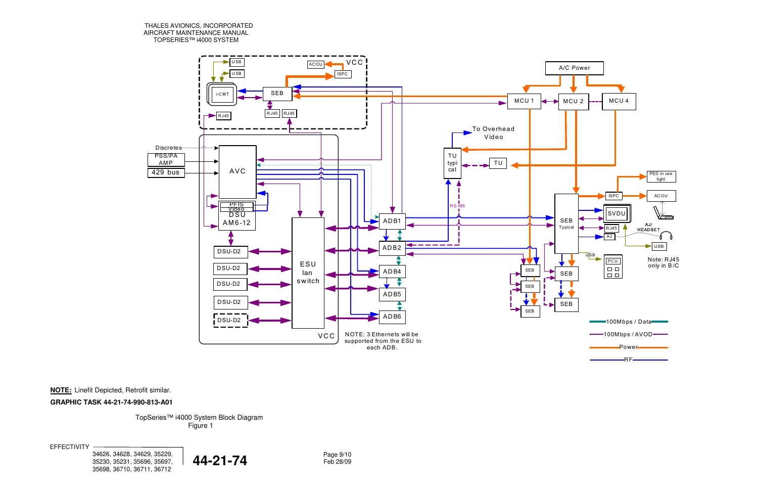
- System Architecture — head-end LRUs, distribution LRUs, seat-end LRUs, system block diagram
- System Functional Description — operator interface and iCMT screens, IFE power activation, broadcast and in-seat audio/video, overhead distributed video, PA and video PA, decompression, moving map, USB and PED connectivity, maintenance screens including content loading and offload
- Line Replaceable Unit Descriptions — AVC, DSU-AM6-12, DSU-D2, ESU-G, ADB, MCU, Programming Module, Tapping Unit, SEB, TPCU-b, 15.4-inch SVDU, 10.4-inch iCMT, 8.9-inch SVDUs, Overhead Electronics Box
- System Wiring — VCC wiring and system wiring for retrofit aircraft
- Component Locations — equipment lists with part numbers and quantities, VCC in the F2 galley, Business Class and Economy Class interconnect diagrams, circuit breaker locations for retrofit aircraft
- Maintenance Practices — system power-up, PDL setup, Phase 1 software download, linefit and retrofit software lists, Phase 2 downloads to DSU-AM6-12, AVC, ESU-G, ADBs, DSU-D2s, SEBs, SVDU-IIWs, TPCU-bs and iCMT, IP sequencing, OEB address assignment, content loading, configuration check, PDL shutdown, full IFE reboot
- Removal/Installation — DSU-AM6-12, ESU-G, AVC, DSU-D2, iCMT, VCC SEB, MCU, TU, ADB, and seat-end SEB, SVDU and TPCU-b replacement
- Adjustment/Test — functional test structured in three levels
- Inspection/Check — visual checks of threaded parts, identification labels, covers and panels, electrical connectors, and wiring
- Cleaning/Painting — equipment exterior cleaning and SVDU screen cleaning
Taken together, those sections give a line technician the architecture of the LAN 767 i4000 installation, the leading particulars of each LRU, where the boxes sit in the VCC and cabin, how to load software and media content through the PDL and iCMT, how to swap the listed LRUs, and how to inspect and clean the hardware after work. Shop-level CMM data for individual boxes is referenced by ATA number rather than reproduced in full.
Head-end, Distribution, and Seat Hardware Named in the Book
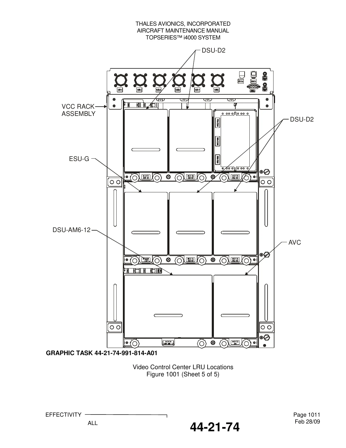
Head-end LRUs in the Video Control Center include the Interactive Cabin Management Terminal (P/N 177792-803), a Seat Electronics Box for the iCMT (P/N 177745-106), Digital Server Unit-AM6-12 (P/N 177900-103), Audio/Video Controller (P/N 177716-103), four Digital Server Unit-D2 units (P/N 177892-102), Ethernet Switching Unit-Gigabit (P/N 178568-102), and the VCC Rack Assembly (P/N 179231-101). The AVC provides video and audio modulation, passenger announcement, overhead video control, and communications, combining traditional audio multiplexer and overhead video control functions. The DSU-AM6-12 stores MPEG-1 or MPEG-2 video on a magnetic hard drive with one to 16 audio tracks in an MPEG-2 transport stream. Each DSU-D2 streams MPEG video, menu-driven databases, interactive games, HTML/HXM, and eCommerce data from disk and uses an ARINC 600 rack interface. The ESU-G is a 4 MCU LRU with two independent 24-port managed Ethernet switches used to form the airborne LAN.
Distribution hardware includes four Master Control Units (P/N 177922-103), Programming Modules (P/N 177923-601 and 177923-602), five Area Distribution Boxes (P/N 177730-106), five Floor Disconnect Boxes (P/N 172781-01), five Tapping Units (P/N 177832-101), and Overhead Electronics Boxes (P/N 179130-101; quantity 98 in the equipment list). A note states retrofit aircraft have OEBs P/N 179130-101 instead of SEBs in seating areas. Business Class seat-group quantities include 15 SEBs, 30 TPCU-b units (P/N 179118-A01), 30 15.4-inch wide-screen SVDUs (P/N 178840-301), and 30 integrated noise-canceling AJMs (P/N 178921-102). Economy Class quantities include 87 SEBs (P/N 176745-106 in that table), 191 TPCU-b units, 188 8.9-inch seat-back SVDUs (P/N 179290-201), three 8.9-inch arm-mount SVDUs (P/N 178850-201), and 191 AJMs (P/N 170777-25).
Leading particulars published for the larger VCC boxes include AVC dimensions of 5.000 in W x 7.850 in H x 12.515 in L, 13.5 lb maximum, 125 W dissipation, and 100–126 VAC 400 Hz power; DSU-AM6-12 dimensions of 10.214 in W x 10.094 in H x 12.530 in L, 28.05 lb maximum, forced-air cooling, and 115 VAC 400 Hz; DSU-D2 12.5 lb maximum, 60 W, 115 VAC 400 Hz single phase, with specified minimum and recommended airflow in CFM; and ESU-G 13 lb maximum, 72 W, 115 VAC 400 Hz, operating temperature −15 to 70 °C (DO-160D Category A2), operating altitude 0 to +50,100 ft, and published MTBF figures for the 24-port switch PCBA and power supply. BITE, AC, DC, SCSI, RUN, POWER, and FAULT indicators are tabulated for the applicable boxes.
Software Load, Content Load, and Return-to-Service Flow
Maintenance Practices explain that aircraft-loadable software can be supplied on CD-ROM or USB and is applied in two phases. Phase 1 loads selected components or packages onto the download server and builds the desired-configuration list that later configuration checks use as the baseline. Phase 2 pushes that list onto each LRU type independently and removes software that is no longer on the list. Download order is head-end components, then distribution components, then seat components. The ADB database must be loaded before IP sequencing. After LRU replacement or any compromise of the system, the manual directs a System Functional Test for return to service. Content loading is driven from the iCMT Content Loading Menu through inventory selection, summary, detail, engineering, and PDL status screens; a dedicated Content Loading Procedure warns not to interrupt aircraft power. Configuration check compares displayed software part numbers for DSU-AM6-12, AVC, ESU-G, ADBs, DSU-D2s, SEBs, SVDUs, TPCU-bs, and iCMT against the current download screen. After all LRUs are loaded, the entire IFE system is rebooted with the MASTER IFE switch beside the iCMT until the LAN Welcome Screen appears.
The VCC sits in the F2 galley. Control-panel drawings identify the MASTER IFE switch, HEAD END POWER switch, SEAT END POWER switch, IFE FAN INOP indicator, USB port, audio jack, three data-loader ports, AC outlet unit, and (on the retrofit panel) ALARM RESET and SMOKE TEST. Linefit component locations that Boeing determined are referred to the Boeing 767 AMM; retrofit LRU locations, Business Class and Economy Class interconnect diagrams, and retrofit circuit-breaker panels are drawn in this book. Additional retrofit parts-breakdown data is pointed to the Thales LAN 767 i4000 Illustrated Parts Catalog 44-22-12.
Use This Manual for LRU Work, Software Loads, and Cabin IFE Checks
With the Thales TopSeries i4000 LAN Airlines Boeing 767 Aircraft Maintenance Manual ATA 44-21-74 Rev 4 in hand, a technician can identify every listed head-end, distribution, and seat LRU by part number, find it in the VCC or cabin, read its connectors and BITE lamps, remove and install the boxes covered in the Removal/Installation section, run Phase 1 and Phase 2 software downloads, load entertainment content from a Portable Data Loader, confirm the configuration list, inspect hardware condition, and clean SVDU screens without solvents or abrasive cloths. Those steps matter because the i4000 system is an Ethernet-based cabin network; loading the wrong package, skipping IP sequencing, or interrupting power mid-load leaves servers, switches, and seat boxes out of the desired configuration. Instant PDF delivery after payment — no shipping wait — so the file can be opened on a laptop or tablet in the hangar or printed for the job card.

Reviews
There are no reviews yet.