Description
Airbus A318 A319 A320 A321 Chapter 24 Electrical Power Aircraft Maintenance Manual AES Rev 40 (2012)
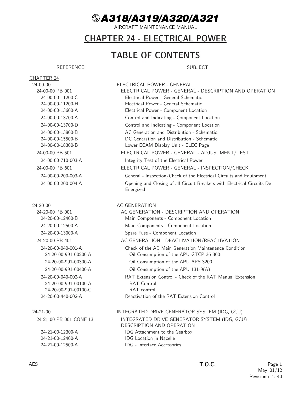
This download is ATA Chapter 24 of the A318/A319/A320/A321 Aircraft Maintenance Manual as issued under AES Revision n˚ 40 dated May 01/12. It is the electrical-power chapter only: generation, conversion, emergency supply, ground power, bus switching, galley load, battery charging and electrical routing/EWIS inspection. Effectivity notes in the text distinguish On A/C ALL, On A/C 003-004, On A/C 005-099 and selected zone differences such as APU generator location on 003-007 versus 008-099.
File Details
- Manual type: Aircraft Maintenance Manual – Chapter 24 Electrical Power
- Brand / models: Airbus A318, A319, A320, A321
- Language: English
- Page count: 1442
- File format: PDF
- Publisher mark: AES
- Revision: n˚ 40
- Date: May 01/12
How the Electrical Network Is Built
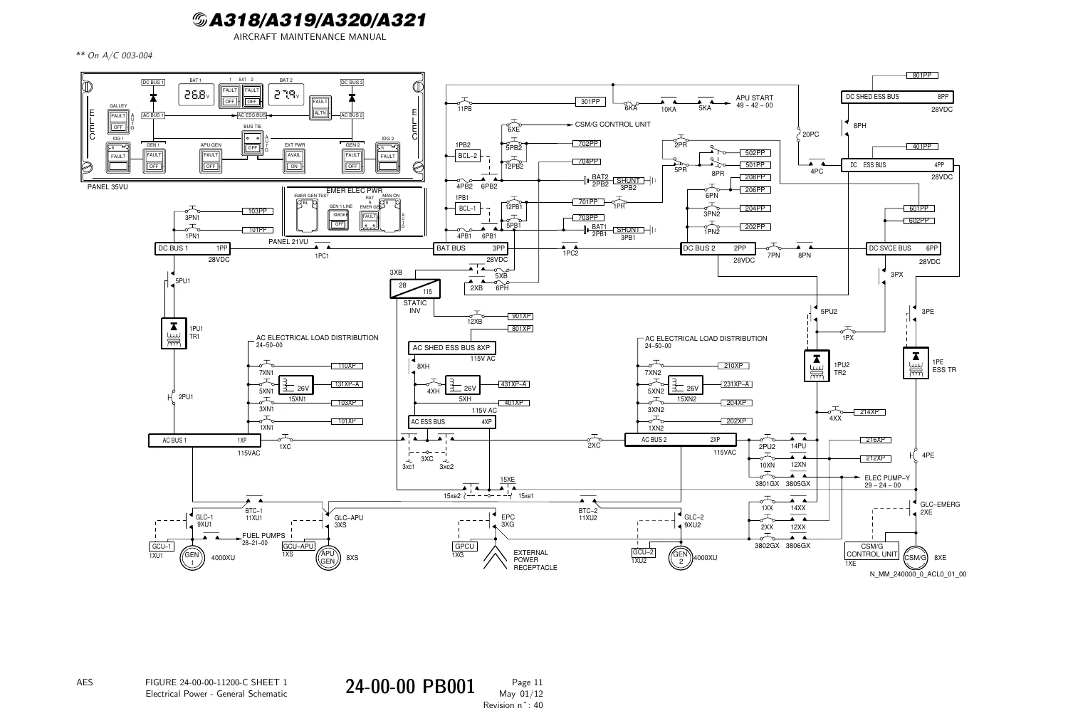
The Airbus A318 A319 A320 A321 Chapter 24 Electrical Power Aircraft Maintenance Manual AES Rev 40 (2012) opens with the general arrangement used on the family. Two Integrated Drive Generators normally supply the aircraft in flight; each engine HP rotor drives one IDG through the accessory gearbox. An APU-driven third generator can replace GEN 1 or GEN 2 in flight and can power the network on the ground when a GPU is not connected. Two Transformer Rectifiers convert AC to DC in normal configuration. After a major generation loss a hydraulically driven Constant Speed Motor/Generator (CSM/G) supplies the systems needed for aircraft control. On the ground a Ground Power Unit can feed the network through the external-power receptacle and GPCU.
Each IDG produces 115/200 VAC, 3-phase, 400 Hz. Leading particulars of the main generator and APU generator are given as 90 KVA at the Point of Regulation (POR) with the same 115 V/200 V three-phase 400 Hz output. The IDG combines a hydromechanical Constant-Speed Drive with the generator so variable engine speed becomes constant generator speed. The APU generator is driven at a nominal 24000 rpm constant speed and is a brushless oil-cooled machine. The CSM/G is listed at 5 KVA at POR, 115/200 VAC, three-phase, 400 Hz, speed-regulated from Blue hydraulic oil. In normal conditions an electric pump supplies Blue; in emergency the RAT supplies Blue. Loss of AC BUS 1 and AC BUS 2 automatically commands the RAT and CSM/G; a guarded MAN ON pushbutton on the EMER ELEC PWR panel provides a manual path that is redundant with automatic RAT logic.
The two IDGs are never electrically coupled. Network 1 comprises AC BUS 1, AC ESS BUS and AC SHED ESS BUS. Network 2 is AC BUS 2. TR1, fed from AC BUS 1, supplies DC BUS 1, DC BAT BUS, DC ESS BUS and DC SHED ESS BUS. Two batteries sit on the DC BAT BUS. TR2, fed from AC BUS 2, supplies DC BUS 2. If TR1 or TR2 fails, the Essential Transformer Rectifier (ESS TR) takes DC ESS and DC SHED ESS. Transfer contactors (BTC 1/2) can feed either AC network from GEN 1, GEN 2, APU GEN or EXT PWR according to source priority: own generator, ground power, APU GEN, then the opposite generator. A BUS TIE pushbutton can lock both BTCs and isolate the channels.
Batteries 2PB1 and 2PB2 are nickel-cadmium packs of twenty cells in a stainless-steel case: 24 V nominal, 23 Ah, 60 cm³ electrolyte reserve and two ventilation ducts. They start the APU in flight and on the ground and back the essential network during RAT deployment and when the emergency generator is not available. Each pack has a Battery Charge Limiter and a shunt. BCL logic includes charge-cycle close/open thresholds (VBAT < 26.5 V with V3PP > 27 V; end of charge when ICH < 4 A), thermal-runaway opening, APU-start closing and hot-bus integrity opening. The static-inverter section describes a unit that converts battery DC into single-phase 115 VAC/400 Hz; the general chapter also records a 350 VA inverter fed from the BAT BUS for loss of both AC buses, while the dedicated 24-28 task block describes a 1000 VA inverter fed from battery 1.
Galley supply is 115 VAC with 50 KVA available for all galleys, split as 30 KVA aft and 20 KVA forward. Automatic and manual galley and bus shedding, commercial-load shedding and C/B TRIPPED warning inhibit/reactivate tasks sit in the distribution ATA blocks. Ground-service AC and DC buses can be energized from external power independently of the full flight network.
Chapters Covered
- 24-00-00 Electrical Power – General: description and operation, general schematics, component and control/indicating locations, AC and DC generation/distribution schematics, Lower ECAM ELEC page, integrity test, inspection of circuits and equipment, opening and closing of circuit breakers with circuits de-energized
- 24-20-00 AC Generation: main-component and spare-fuse locations; AC main-generation maintenance condition; APU oil-consumption data for GTCP 36-300, APS 3200 and 131-9(A); RAT manual-extension check, RAT control and reactivation
- 24-21-00 Integrated Drive Generator System (IDG, GCU): gearbox attachment, nacelle location, interface accessories, ELEC control panel, fuel-cooled IDG oil cooler and cables, speed-regulation loop, oil-system and internal schematics, drive control and indicating, IDG oil low-pressure / overheat advisory / overheat and disconnect ECAM pages; preservation/storage; servicing after oil chemical contamination and with DPI extended; drain, discard filter and replenish; oil-type change; disconnect/reconnect tests engine static and in operation; frequency system test (P/N 766219); governor adjustment screw; filter-element inspection and oil-leak visual check
- 24-21-15 / 24-21-41 / 24-21-42 / 24-21-43 / 24-21-49 / 24-21-51: IDG oil-temperature thermocouple; QAD adapter removal/installation and tension-bolt torque check; fuel-cooled oil-cooler R&I and cleaning; IDG cables; cooler-oil tubing R&I and general check; IDG 1(2) removal/installation; oil-filter R&I; oil-level and DPI checks
- 24-22-00 AC Main Generation: component locations, normal-configuration schematics, zone of protection, EGIU schematic, flip-flop and SDAC communication, current-transformer block diagrams, Channel 1 schematic, GLC/BTC logic, GLC-1 and BTC supplies, GEN FAULT/OFF and AC BUS FAULT ECAM pages, smoke detection; GLC-1 opening in the smoke procedure and transfer-inhibition tests; AC current transformers, TDC AC sensors, EGIU, GCU, lightning-protection modules and contactors
- 24-23-00 AC Auxiliary Generation: APU generator configuration, current transformers, auxiliary-generation and APU GLC schematics, APU GEN FAULT ECAM; deactivation by substitution kit or quill-shaft removal and reactivation; APU GCU, APU generator 8XS (including minilift hoist) and APU GLC
- 24-24-00 AC Emergency Generation: component locations, emergency generating and switching schematics, EMER & AC ESS contactor logic, RAT extension and CSM/G control logic, GCU EMER MCDU test, emergency and smoke ECAM configurations, available functions in emergency configuration; operational tests of the emergency generation system and GCU from CFDS; CSM/G control unit, CSM/G 8XE, EMER GLC and AC ESS BUS contactors
- 24-25-00 AC Essential Generation Switching: loss-of-AC-BUS-1XP logic, operational test, AC essential bus switching contactor
- 24-26-00 / 24-27-00 / 24-28-00: galley supply control and overload ECAM; AC generation monitoring and indicating; GEN FAULT and automatic galley-shedding tests; static inverter schematic, operational tests from external power or APU, inverter and inverter-contactor R&I
- 24-30-00 / 24-32-00 / 24-34-00 / 24-35-00 DC generation family: TR1/TR2 loss diagrams, CFDS architecture with TRs and BCLs, battery charging cycle on the operative BCL, TR2 deactivation/reactivation, emergency generation with one normal TR failed; TR component description, contactor logic, TR fault ECAM and TR reset; DC generation switching test; essential TR and contactors; DC NORM BUS and DC ESS BUS supply logic
- 24-37-00 / 24-38-00 Batteries and indicating: battery and shunt locations, BCL cockpit schematics, BAT 1/2 FAULT ECAM, BCL operational tests with and without CFDS, visual battery inspection, BCL/battery/shunt/line-contactor R&I, batteries 1 and 2 removal for restoration
- 24-40-00 / 24-41-00 / 24-42-00 / 24-43-00 External and ground-service power: GPCU locations and schematics, EPC supply, Class 3 fault reading on MCDU, energize/de-energize from EXT PWR, APU or engine 1(2), receptacle inspection, GPCU CFDS check, receptacle and EPC R&I; AC and DC ground-service bus control, energize/de-energize of the ground-service network
- 24-50-00 through 24-56-00 AC load distribution: normal-flight, emergency and smoke configurations for the whole AC/DC network; C/B provisions on panels 49VU, 105/106VU, 121–125VU, 2000VU and 2001VU; galley-supply deactivation/reactivation; commercial-load shedding test; 115/26 VAC autotransformers; AC service and shed-essential contactors; galley power-supply schematics and panel-200VU contactors
- 24-60-00 / 24-61-00 / 24-62-00 / 24-67-00 DC load distribution: DC EMER CONFIG, CSM/G and landing-gear-extended supply pages; DC BUS 1/2, combined BUS and BAT BUS FAULT ECAM; DC service and shed-bus contactors and bus-1/bus-2 contactor modules; DC ESS BUS FAULT and SHED pages; refueling on battery schematic and refuel/defuel panel location
- 24-92-00 Electrical routing: IDG feeder removal/installation on pylon and wing; conduit end-fitting inspections from wing leading/trailing edges, wing tip, air-conditioning compartment, vertical and horizontal stabilizer, flap-track fairing, MLG well, dry bay and fuselage tail; harness GVI and detailed EWIS inspections in avionics bays, passenger and cargo compartments, fuel tank, vent surge tank, pylons, keel beam and bulk cargo; bonding-lead inspection on movable surfaces; loop-tester connector tightness check; EWIS cleaning tasks when contaminated
Taken together, the chapter gives a line technician the description-and-operation baseline, the ECAM electrical pages, the R&I and servicing tasks for generators, coolers, filters, contactors, TRs, batteries and the GPCU, plus the EWIS inspection map that occupies the last several hundred pages. Configuration notes keep the reader on the correct schematic when an aircraft falls in the 003-004 versus 005-099 group.
Complete PDF Bookmark Tree
Complete Bookmarks
The complete bookmarks in the “Airbus A318 A319 A320 A321 Chapter 24 Electrical Power Aircraft Maintenance Manual AES Rev 40 (2012)” are as follows:
Manual Front Matter
Chapter 05 – TIME LIMITS – MAINTENANCE CHECKS
Chapter 06 – DIMENSIONS AND AREAS
Chapter 07 – LIFTING AND SHORING
Chapter 08 – LEVELING AND WEIGHING
Chapter 09 – TOWING AND TAXIING
Chapter 10 – PARKING, MOORING, STORAGE & RETURN TO SERVICE
Chapter 11 – PLACARDS AND MARKINGS
Chapter 12 – SERVICING
Chapter 20 – STANDARD PRACTICES – AIRFRAME
Chapter 21 – AIR CONDITIONING
Chapter 22 – AUTO FLIGHT
Chapter 23 – COMMUNICATIONS
+Chapter 24 – ELECTRICAL POWERp. 1
Table of Contentsp. 1
+24-00 – ELECTRICAL POWER – GENERALp. 26
+24-00-00 – ELECTRICAL POWER – GENERALp. 26
+24-00-00 PB 001 CONF 00 – ELECTRICAL POWER – GENERAL – DESCRIPTION AND OPERATIONp. 26
Generalp. 26
Component Locationp. 28
System Descriptionp. 29
Controls and Indications Related to Electrical Generation and Distributionp. 34
Figure 24-00-00-11200-C – Electrical Power – General Schematicp. 36
Figure 24-00-00-11200-H – Electrical Power – General Schematicp. 37
Figure 24-00-00-13600-A – Electrical Power – Component Locationp. 38
Figure 24-00-00-13700-A – Control and Indicating – Component Locationp. 39
Figure 24-00-00-13700-D – Control and Indicating – Component Locationp. 40
Figure 24-00-00-13800-B – AC Generation and Distribution – Schematicp. 41
Figure 24-00-00-15500-B – DC Generation and Distribution – Schematicp. 42
Figure 24-00-00-18300-B – Lower ECAM Display Unit – ELEC Pagep. 43
+24-00-00 PB 501 CONF 00 – ELECTRICAL POWER – GENERAL – ADJUSTMENT/TESTp. 45
24-00-00-710-003-A – Integrity Test of the Electrical Powerp. 45
+24-00-00 PB 601 CONF 00 – ELECTRICAL POWER – GENERAL – INSPECTION/CHECKp. 53
24-00-00-200-003-A – General – Inspection/Check of the Electrical Circuits and Equipmentp. 53
24-00-00-200-004-A – Opening and Closing of all Circuit Breakers with Electrical Circuits De-Energizedp. 56
+24-20 – AC GENERATIONp. 58
+24-20-00 – AC GENERATIONp. 58
+24-20-00 PB 001 CONF 00 – AC GENERATION – DESCRIPTION AND OPERATIONp. 58
Generalp. 58
Component Locationp. 59
Figure 24-20-00-12400-B – Main Components – Component Locationp. 61
Figure 24-20-00-12500-A – Main Components – Component Locationp. 62
Figure 24-20-00-13000-A – Spare Fuse – Component Locationp. 63
+24-20-00 PB 401 CONF 00 – AC GENERATION – DEACTIVATION/REACTIVATIONp. 64
+24-20-00-040-001-A – Check of the AC Main Generation Maintenance Conditionp. 64
Figure 24-20-00-991-00200-A – Oil Consumption of the APU GTCP 36-300p. 68
Figure 24-20-00-991-00300-A – Oil Consumption of the APU APS 3200p. 69
Figure 24-20-00-991-00400-A – Oil Consumption of the APU 131-9(A)p. 70
+24-20-00-040-002-A – RAT Extension Control – Check of the RAT Manual Extensionp. 71
Figure 24-20-00-991-00100-A – RAT Controlp. 74
Figure 24-20-00-991-00100-C – RAT controlp. 75
24-20-00-440-002-A – Reactivation of the RAT Extension Controlp. 76
+24-21 – INTEGRATED DRIVE GENERATOR SYSTEM (IDG, GCU)p. 77
+24-21-00 – INTEGRATED DRIVE GENERATOR SYSTEM (IDG, GCU)p. 77
+24-21-00 PB 001 CONF 13 – INTEGRATED DRIVE GENERATOR SYSTEM (IDG, GCU) – DESCRIPTION AND OPERATIONp. 77
Generalp. 77
Component Locationp. 78
System Descriptionp. 79
Power Supplyp. 80
Interfacep. 81
Descriptionp. 82
Operation/Control and Indicatingp. 85
Figure 24-21-00-12300-A – IDG Attachment to the Gearboxp. 87
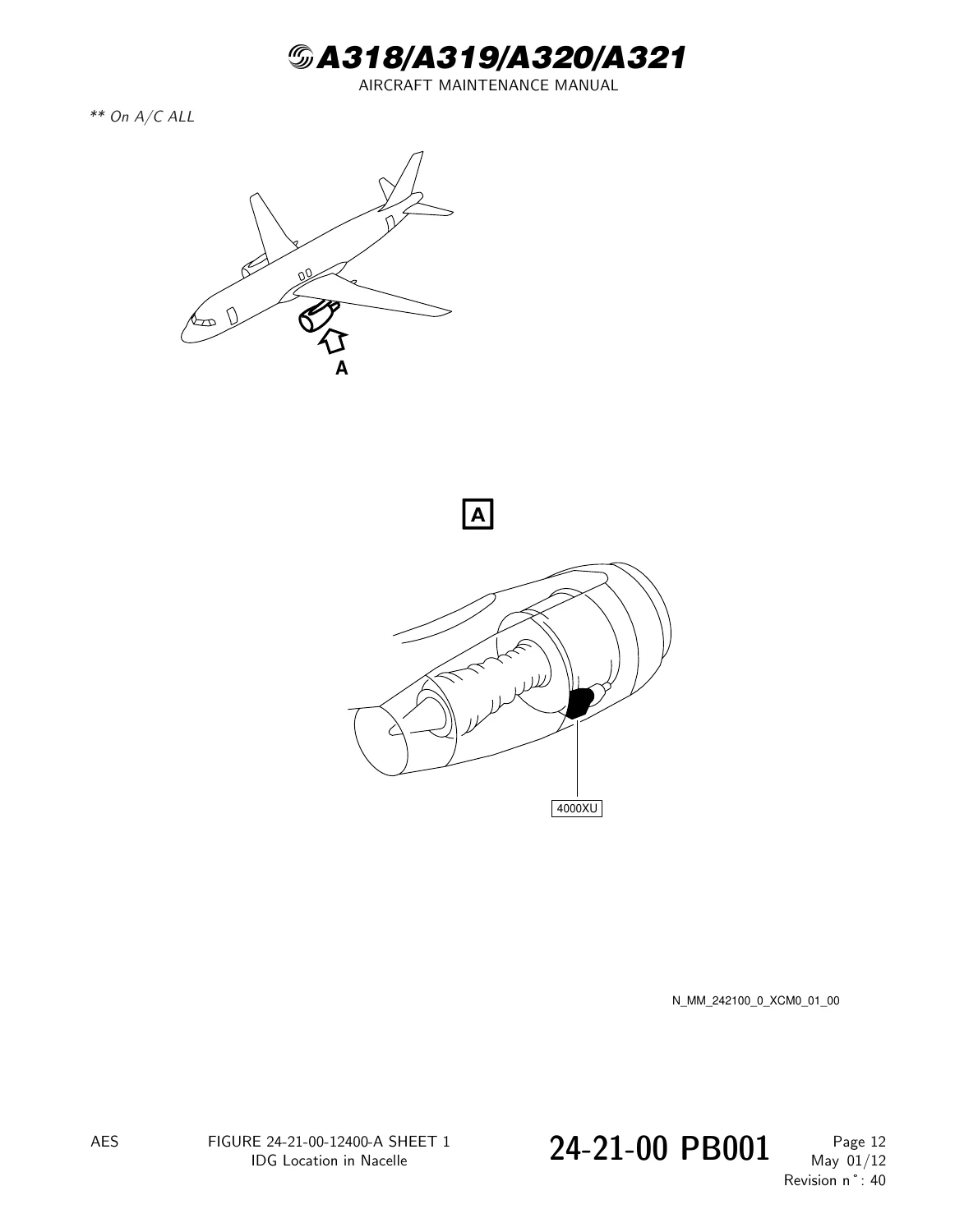
Figure 24-21-00-12400-A – IDG Location in Nacellep. 88
Figure 24-21-00-12500-A – IDG – Interface Accessoriesp. 89
Figure 24-21-00-12600-A – ELEC Control Panel – Locationp. 90
Figure 24-21-00-12800-A – Fuel-Cooled IDG Oil Cooler and Cables – Locationp. 91
Figure 24-21-00-19900-A – IDG – Speed Regulation Loopp. 92
Figure 24-21-00-21400-A – IDG Oil System – Schematicp. 93
Figure 24-21-00-21600-A – IDG – Internal Schematicp. 94
Figure 24-21-00-24600-A – IDG System – Generator Drive Control and Indicatingp. 95
Figure 24-21-00-24700-A – IDG 1 Oil Low Pressure – Upper and Lower ECAM Display Unitsp. 96
Figure 24-21-00-24800-A – IDG 1 Oil Overheat Advisory – Upper and Lower ECAM Display Unitsp. 98
Figure 24-21-00-24900-A – IDG 1 Oil Overheat – Upper and Lower ECAM Display Unitsp. 100
Figure 24-21-00-25000-A – IDG 1 Disconnect – Lower ECAM Display Unitp. 102
+24-21-00 PB 201 CONF 13 – INTEGRATED DRIVE GENERATOR SYSTEM (IDG, GCU) – MAINTENANCE PRACTICESp. 103
24-21-00-600-040-A – Preservation/Storage/Return to Service of the IDGp. 103
+24-21-00 PB 301 CONF 13 – INTEGRATED DRIVE GENERATOR SYSTEM (IDG, GCU) – SERVICINGp. 106
+24-21-00-612-044-A – Servicing of the IDG after Oil Chemical Contaminationp. 106
Figure 24-21-00-991-90000-A – Servicing of IDG after Oil Chemical Contaminationp. 111
+24-21-00-612-044-A-01 – Servicing of the IDG after Oil Chemical Contamination and Extension of the Oil-Filter Differential-Pressure Indicator (DPI)p. 112
Figure 24-21-00-991-90900-A – Servicing of the IDG after Oil Contamination and with the DPI Outp. 116
+24-21-00-920-041-A – Drain IDG Oil System, Discard Filter Element(s) and Replenishp. 117
Figure 24-21-00-991-91000-B – IDG Oil Filterp. 124
+24-21-00-612-047-A – IDG Oil-Type Changep. 126
Figure 24-21-00-991-91100-A – Oil Type Change – IDGp. 131
+24-21-00 PB 501 CONF 13 – INTEGRATED DRIVE GENERATOR SYSTEM (IDG, GCU) – ADJUSTMENT/TESTp. 132
24-21-00-710-042-A – Operational Test of the IDG Disconnect and Reconnect (Reset) Function – Engine Staticp. 132
+24-21-00-730-041-A – System Test of the IDG Frequency (P/N 766219)p. 136
Figure 24-21-00-991-92100-A – Governor Adjustment Screw – IDGp. 139
24-21-00-720-042-A – Operational Test of the IDG Disconnect and Reconnect (Reset) Function – Engine in Operationp. 140
+24-21-00 PB 601 CONF 13 – INTEGRATED DRIVE GENERATOR SYSTEM (IDG, GCU) – INSPECTION/CHECKp. 143
24-21-00-210-045-A – Inspection of the Filter Element(s)p. 143
24-21-00-210-048-A – Visual Inspection of the IDG for Oil Leaks and Check of the Electrical Circuitsp. 146
+24-21-00-210-048-A-01 – Visual Inspection of the IDG for Oil Leakage Engine Static and Check of the Electrical Circuitsp. 149
Figure 24-21-00-991-20000-B – Connection of the Test Tool on the IDGp. 153
+24-21-15 – THERMOCOUPLE – IDG OIL TEMPERATUREp. 154
+24-21-15 PB 401 CONF 13 – THERMOCOUPLE – IDG OIL TEMPERATURE – REMOVAL/INSTALLATIONp. 154
+24-21-15-000-010-A – Removal of the IDG Oil Temperature Thermocouplep. 154
Figure 24-21-15-991-15000-A – IDG Oil Temperature thermocouplep. 156
24-21-15-400-010-A – Installation of the IDG Oil Temperature Thermocouplep. 157
+24-21-41 – ADAPTER – QUICK ATTACH/DETACH, IDGp. 161
+24-21-41 PB 401 CONF 13 – COUPLING – QAD, IDG – REMOVAL/INSTALLATIONp. 161
+24-21-41-000-010-A – Removal of the Quick Attach/Detach (QAD) Adapter of the IDGp. 161
Figure 24-21-41-991-15000-A – Quick Attach/Detach (QAD) Adapter (Coupling)p. 163
Figure 24-21-41-991-15200-A – Removal of the QAD Adapter (Coupling)p. 164
24-21-41-400-010-A – Installation of the Quick Attach/Detach (QAD) Adapter of the IDGp. 165
+24-21-41 PB 601 CONF 13 – COUPLING – QAD, IDG – INSPECTION/CHECKp. 168
+24-21-41-200-010-A – Torque Check of the Quick Attach-Detach (QAD) Adapter Tension-Boltp. 168
Figure 24-21-41-991-15100-A – IDG QAD Couplingp. 171
+24-21-42 – COOLER – FUEL COOLED IDG OILp. 172
+24-21-42 PB 401 CONF 13 – IDG OIL COOLER – FUEL COOLED – REMOVAL/INSTALLATIONp. 172
+24-21-42-000-010-B – Removal of the Fuel-Cooled IDG Oil-Coolerp. 172
Figure 24-21-42-991-15000-A – Fuel-Cooled IDG Oil-Coolerp. 175
Figure 24-21-42-991-15300-A – Fuel-Cooled IDG Oil-Coolerp. 176
Figure 24-21-42-991-15100-A – Fuel-Cooled IDG Oil-Coolerp. 177
Figure 24-21-42-991-15200-B – Fuel-Cooled IDG Oil-Coolerp. 178
24-21-42-400-010-B – Installation of the Fuel-Cooled IDG Oil-Coolerp. 179
+24-21-42 PB 701 CONF 13 – IDG OIL COOLER – FUEL COOLED – CLEANING/PAINTINGp. 184
24-21-42-100-040-A – Cleaning of the Fuel Cooled IDG Oil Coolerp. 184
+24-21-43 – IDG – CABLESp. 185
+24-21-43 PB 401 CONF 13 – IDG – CABLES – REMOVAL/INSTALLATIONp. 185
+24-21-43-000-010-A – Removal of the IDG Cablesp. 185
Figure 24-21-43-991-15000-A – IDG Cablesp. 187
24-21-43-400-010-A – Installation of the IDG Cablesp. 190
+24-21-49 – TUBING – IDG COOLER OILp. 194
+24-21-49 PB 401 CONF 13 – TUBING – IDG COOLER OIL – REMOVAL/INSTALLATIONp. 194
+24-21-49-000-041-A – Removal of the Tubings – IDG Cooling Oilp. 194
Figure 24-21-49-991-90100-A – Tubings – IDG Cooling Oilp. 197
24-21-49-400-041-A – Installation of the Tubing – IDG Cooler Oilp. 198
+24-21-49 PB 601 CONF 13 – TUBING – IDG COOLER OIL – INSPECTION/CHECKp. 202
+24-21-49-200-010-A – General Check of the IDG Oil Cooling Tubesp. 202
Figure 24-21-49-991-15000-A – IDG Oil-Cooling Tubesp. 206
+24-21-51 – GENERATOR – INTEGRATED DRIVE (IDG)p. 207
+24-21-51 PB 401 CONF 13 – GENERATOR – INTEGRATED DRIVE (IDG) – REMOVAL/INSTALLATIONp. 207
+24-21-51-000-010-A – Removal of the Integrated Drive Generator -IDG 1(2)p. 207
Figure 24-21-51-991-15200-A – Integrated Drive Generator (IDG)p. 212
Figure 24-21-51-991-15100-A – Integrated Drive Generator (IDG)p. 214
Figure 24-21-51-991-15000-A – Integrated Drive Generator (IDG)p. 217
24-21-51-400-010-A – Installation of the Integrated Drive Generator -IDG 1(2)p. 218
+24-21-51-000-011-A – Removal of the IDG Oil Filter(s)p. 228
Figure 24-21-51-991-15400-B – IDG Oil Filterp. 230
24-21-51-400-011-A – Installation of the IDG Oil Filter(s)p. 231
+24-21-51 PB 601 CONF 13 – GENERATOR – INTEGRATED DRIVE (IDG) – INSPECTION/CHECKp. 234
24-21-51-200-010-A – Check of the Oil Level and Filter Differential Pressure Indicator (DPI)p. 234
+24-21-51-200-011-A – Check IDG Oil Filter Differential Pressure Indicator (DPI)p. 236
Figure 24-21-51-991-15300-A – Differential Pressure Indicator (DPI) of the Oil Filterp. 238
+24-22 – AC MAIN GENERATIONp. 239
+24-22-00 – AC MAIN GENERATIONp. 239
+24-22-00 PB 001 CONF 00 – AC MAIN GENERATION – DESCRIPTION AND OPERATIONp. 239
Generalp. 239
Component Locationp. 240
System Descriptionp. 241
Component Descriptionp. 242
Operation/Control and Indicatingp. 254
Figure 24-22-00-12400-A – AC Main Generation – Component Locationp. 256
Figure 24-22-00-12400-B – AC Main Generation – Component Locationp. 258
Figure 24-22-00-12500-B – AC Main Generation – Component Locationp. 260
Figure 24-22-00-13700-C – AC Main Generation (Normal Configuration) – General Schematicp. 262
Figure 24-22-00-13700-H – AC Main Generation (Normal Configuration) – General Schematicp. 263
Figure 24-22-00-15500-A – Zone of Protectionp. 264
Figure 24-22-00-15700-B – Electrical Generation Interface Unit – Schematic Diagramp. 265
Figure 24-22-00-15800-A – Flip-Flop Circuit – Block Diagramp. 266
Figure 24-22-00-16000-A – SDAC Communication – Block Diagramp. 267
Figure 24-22-00-17900-A – Current Transformers – Block Diagramp. 268
Figure 24-22-00-19500-E – AC Main Generation Channel 1 – Schematic Diagramp. 269
Figure 24-22-00-19600-B – GLC/BTC Logic – Schematic Diagramp. 272
Figure 24-22-00-19700-A – GLC-1 Supply – Schematic Diagramp. 274
Figure 24-22-00-19900-A – GEN 1 FAULT – Upper and Lower ECAM Display Unitp. 275
Figure 24-22-00-20000-A – GEN 1 OFF – Upper and Lower ECAM Display Unitp. 278
Figure 24-22-00-20100-A – GEN 2 OFF _ Upper and Lower ECAM Display Unitp. 280
Figure 24-22-00-20500-A – BTC-1 Supply – Schematic Diagramp. 282
Figure 24-22-00-20800-C – BTC-2 Supply – Schematic Diagramp. 283
Figure 24-22-00-21000-A – AC BUS 1 Fault – Upper and Lower ECAM Display Unitp. 284
Figure 24-22-00-21100-A – AC BUS 2 Fault – Upper and Lower ECAM Display Unitp. 286
Figure 24-22-00-21500-B – Smoke Detection – Upper and Lower ECAM Display Unitp. 288
+24-22-00 PB 501 CONF 00 – AC MAIN GENERATION – ADJUSTMENT/TESTp. 291
24-22-00-710-001-A – Operational Test of the Generator Line Contactor (GLC-1) Opening in the Smoke Procedurep. 291
24-22-00-710-002-A – Operational Test of the Transfer Inhibitionp. 294
+24-22-17 – CURRENT TRANSFORMER – ACp. 296
+24-22-17 PB 401 CONF 00 – CURRENT TRANSFORMER – AC – REMOVAL/INSTALLATIONp. 296
+24-22-17-000-001-A – Removal of the AC Current Transformersp. 296
Figure 24-22-17-991-00300-A – AC Current Transformer (42XU3, 42XU4)p. 301
Figure 24-22-17-991-00400-A – AC Current Transformer (42XU1, 42XU2)p. 302
Figure 24-22-17-991-00300-B – AC Current Transformer (42XU3, 42XU4)p. 303
Figure 24-22-17-991-00400-B – AC Current Transformer (42XU1, 42XU2)p. 304
24-22-17-400-001-A – Installation of the AC Current Transformersp. 305
+24-22-17-000-002-A – Removal of the AC Current Transformersp. 315
Figure 24-22-17-991-00200-A – AC Current Transformer (41XU1, 41XU2)p. 317
24-22-17-400-002-A – Installation of the AC Current Transformersp. 318
+24-22-17-000-003-A – Removal of the AC Current Transformersp. 322
Figure 24-22-17-991-00500-B – AC Current Transformer (51XU1, 51XU2)p. 324
24-22-17-400-003-A – Installation of the AC Current Transformersp. 325
+24-22-18 – SENSOR – TDC ACp. 328
+24-22-18 PB 401 CONF 00 – SENSOR – TDC AC – REMOVAL/INSTALLATIONp. 328
+24-22-18-000-001-A – Removal of the TDC AC Sensor 1(2)p. 328
Figure 24-22-18-991-00100-A – Time Delay Closing (TDC) AC Sensorp. 330
24-22-18-400-001-A – Installation of the TDC AC Sensor 1(2)p. 331
+24-22-33 – ELECTRICAL GENERATION INTERFACE UNIT (EGIU)p. 333
+24-22-33 PB 401 CONF 00 – ELECTRICAL GENERATION INTERFACE UNIT (EGIU) – REMOVAL/INSTALLATIONp. 333
+24-22-33-000-001-A – Removal of the EGIU-1(2)p. 333
Figure 24-22-33-991-00100-A – Electrical Generation Interface Unit 1(2)p. 335
24-22-33-400-002-A – Installation of the EGIU-1(2)p. 336
+24-22-34 – CONTROL UNIT – GENERATOR (GCU)p. 340
+24-22-34 PB 401 CONF 00 – CONTROL UNIT – GENERATOR (GCU) – REMOVAL/INSTALLATIONp. 340
+24-22-34-000-001-A – Removal of the GCU-1(2)p. 340
Figure 24-22-34-991-00100-A – Generator Control Unit 1(2) GCU-1(2)p. 342
24-22-34-400-001-A – Installation of the GCU-1(2)p. 343
+24-22-51 – MODULE – LIGHTNING PROTECTIONp. 346
+24-22-51 PB 401 CONF 00 – MODULE – LIGHTNING PROTECTION – REMOVAL/INSTALLATIONp. 346
+24-22-51-000-001-A – Removal of the Lightning Protection Modulesp. 346
Figure 24-22-51-991-00100-A – Lightning Protection Modulep. 349
Figure 24-22-51-991-00100-B – Lightning Protection Modulep. 350
24-22-51-400-001-A – Installation of the Lightning Protection Modulesp. 351
+24-22-51 PB 601 CONF 00 – MODULE – LIGHTNING PROTECTION – INSPECTION/CHECKp. 354
24-22-51-200-001-A – Check of the Lightning Protection Modulesp. 354
+24-22-55 – CONTACTORp. 356
+24-22-55 PB 401 CONF 00 – CONTACTOR – REMOVAL/INSTALLATIONp. 356
+24-22-55-000-001-A – Removal of the Contactorsp. 356
Figure 24-22-55-991-00100-A – Contactorsp. 359
Figure 24-22-55-991-00100-B – Contactorsp. 360
24-22-55-400-002-A – Installation of the Contactorsp. 361
+24-23 – AC AUXILIARY GENERATIONp. 366
+24-23-00 – AC AUXILIARY GENERATIONp. 366
+24-23-00 PB 001 CONF 00 – AC AUXILIARY GENERATION – DESCRIPTION AND OPERATIONp. 366
Generalp. 366
Component Locationp. 367
System Descriptionp. 368
Component Descriptionp. 369
Operation/Control and Indicatingp. 371
Figure 24-23-00-12300-A – AC Auxiliary Generation (APU Generator GCU) Component Locationp. 372
Figure 24-23-00-12300-B – AC Auxiliary Generation (APU Generator GCU) Component Locationp. 374
Figure 24-23-00-12400-A – AC Auxiliary Generation (APU Generator GCU) Component Locationp. 376
Figure 24-23-00-13800-C – APU Generator Configuration – Block Diagramp. 377
Figure 24-23-00-13800-G – APU Generator Configuration – Block Diagramp. 378
Figure 24-23-00-16800-A – Current Transformers – Block Diagramp. 379
Figure 24-23-00-18300-E – Auxiliary Generation Operation – Schematic Diagramp. 380
Figure 24-23-00-18500-A – GLC – APU Supply – Schematic Diagramp. 382
Figure 24-23-00-18700-A – APU GEN FAULT – Upper and Lower ECAM Display Unitp. 383
+24-23-00 PB 401 CONF 00 – AC AUXILIARY GENERATION – DEACTIVATION/REACTIVATIONp. 386
+24-23-00-040-001-A – Deactivation of the APU Generator by Installation of the Substitution Kitp. 386
Figure 24-23-00-991-00100-A – Components for Flight without an APU Generator Installedp. 392
24-23-00-440-001-A – Reactivation of the APU Generator after Removal of the Substitution Kitp. 393
+24-23-00-040-002-A – Deactivation of the APU Generator by Removal of the Quill Shaftp. 397
Figure 24-23-00-991-00200-A – APU Generator without Quill Shaftp. 400
24-23-00-440-002-A – Reactivation of the APU Generator after Quill Shaft Removalp. 401
+24-23-17 – CURRENT TRANSFORMER – ACp. 404
+24-23-17 PB 401 CONF 00 – CURRENT TRANSFORMER – AC – REMOVAL/INSTALLATIONp. 404
+24-23-17-000-001-A – Removal of the AC Current Transformerp. 404
Figure 24-23-17-991-00300-A – AC Current Transformer – Block Diagramp. 407
Figure 24-23-17-991-00400-A – AC Current Transformerp. 408
Figure 24-23-17-991-00400-B – AC Current Transformerp. 409
24-23-17-400-001-A – Installation of the AC Current Transformerp. 410
+24-23-34 – CONTROL UNIT – GENERATOR (GCU)p. 415
+24-23-34 PB 401 CONF 00 – CONTROL UNIT – GENERATOR (GCU) – REMOVAL/INSTALLATIONp. 415
+24-23-34-000-001-A – Removal of the GCU-APUp. 415
Figure 24-23-34-991-00100-A – APU Generator Control Unit (GCU)p. 417
24-23-34-400-001-A – Installation of the GCU-APUp. 418
+24-23-51 – GENERATOR – APUp. 421
+24-23-51 PB 401 CONF 00 – GENERATOR – APU – REMOVAL/INSTALLATIONp. 421
+24-23-51-000-001-A – Removal of the APU Generatorp. 421
Figure 24-23-51-991-00100-B – APU Generator 8XSp. 425
Figure 24-23-51-991-00300-B – APU Generator Safety Cablep. 426
+24-23-51-000-001-A-01 – Removal of the APU Generator with the Minilift Hoistp. 427
Figure 24-23-51-991-00500-B – APU Generator 8XSp. 431
Figure 24-23-51-991-00600-B – APU Generator Hoistp. 432
24-23-51-400-001-A – Installation of the APU Generatorp. 433
24-23-51-400-001-A-01 – Installation of the APU Generator with the Minilift Hoistp. 438
+24-23-55 – CONTACTORp. 444
+24-23-55 PB 401 CONF 00 – CONTACTOR – REMOVAL/INSTALLATIONp. 444
+24-23-55-000-001-A – Removal of the APU GLCp. 444
Figure 24-23-55-991-00100-A – Contactorp. 447
Figure 24-23-55-991-00100-B – Contactorp. 448
24-23-55-400-001-A – Installation of the APU GLCp. 449
+24-24 – AC EMERGENCY GENERATIONp. 453
+24-24-00 – AC EMERGENCY GENERATIONp. 453
+24-24-00 PB 001 CONF 00 – AC EMERGENCY GENERATION – DESCRIPTION AND OPERATIONp. 453
Generalp. 453
Component Locationp. 454
System Descriptionp. 455
Component Descriptionp. 456
Operationp. 457
Figure 24-24-00-12300-B – AC Emergency Generation – Component Locationp. 463
Figure 24-24-00-12400-A – AC Emergency Generation – Component Locationp. 464
Figure 24-24-00-12500-A – AC Emergency Generation – Component Locationp. 465
Figure 24-24-00-13900-C – Electrical Emergency Generating System – Schematicp. 466
Figure 24-24-00-13900-D – Electrical Emergency Generating System – Schematicp. 467
Figure 24-24-00-17000-D – Electrical Emergency Switching – Schematicp. 468
Figure 24-24-00-17100-C – EMER & AC ESS BUS Contactors Control – Logic Diagramp. 469
Figure 24-24-00-17200-D – RAT Extension Logic & CSM/G Control Logic – Schematicp. 470
Figure 24-24-00-17200-E – RAT Extension Logic and CSM/G Control Logic – Schematicp. 471
Figure 24-24-00-17400-F – Electrical Emergency Generation System – Control Systemp. 472
Figure 24-24-00-17400-G – Electrical Emergency Generation System – Control Systemp. 473
Figure 24-24-00-17600-B – Test Procedure for GCU EMER by MCDUp. 474
Figure 24-24-00-18000-B – Electrical Emergency Configuration – Upper and Lower ECAM Display Unitp. 475
Figure 24-24-00-18000-C – Electrical Emergency Configuration – Upper and Lower ECAM Display Unitp. 476
Figure 24-24-00-18200-B – ELectrical Emergency Configuration During RAT Deployment and in Landing Gear Extented Configurationp. 477
Figure 24-24-00-18300-A – ESS BUSES ON BAT – Upper and Lower ECAM Display Unitp. 478
Figure 24-24-00-18500-B – Electrical Emergency Configuration with CSM/G Runningp. 479
Figure 24-24-00-18700-B – Electrical Emergency Configuration on the Ground with speed < 50ktsp. 480
Figure 24-24-00-18800-A – Available Functions in Emergency Configurationp. 481
Figure 24-24-00-18800-B – Available Functions in Emergency Configurationp. 482
Figure 24-24-00-18900-A – Available Functions in Emergency Configurationp. 483
Figure 24-24-00-18900-B – Available Functions in Emergency Configurationp. 484
Figure 24-24-00-19000-A – Available Functions in Emergency Configurationp. 485
Figure 24-24-00-19000-B – Available Functions in Emergency Configurationp. 486
Figure 24-24-00-19100-A – Available Functions in Emergency Configurationp. 487
Figure 24-24-00-19100-B – Available Functions in Emergency Configurationp. 488
Figure 24-24-00-19200-A – Available Functions in Emergency Configurationp. 489
Figure 24-24-00-19200-B – Available Functions IN Emergency Configurationp. 490
Figure 24-24-00-19300-C – Available Functions in Emergency Configurationp. 491
Figure 24-24-00-19300-D – Available Functions in Emergency Configurationp. 492
Figure 24-24-00-19700-B – Smoke Detection – Upper and Lower ECAM Display Unitp. 493
Figure 24-24-00-19800-B – Electrical Smoke Configurationp. 495
+24-24-00 PB 501 CONF 00 – AC EMERGENCY GENERATION – ADJUSTMENT/TESTp. 496
24-24-00-710-001-A – Operational Test of the Emergency Generation Systemp. 496
24-24-00-710-002-A – Operational Test of the Emergency Generator Control Unit (GCU) from Centralized Fault Display System (CFDS)p. 500
+24-24-34 – CONTROL UNIT – CSM/Gp. 502
+24-24-34 PB 401 CONF 00 – CONTROL UNIT – CSM/G – REMOVAL/INSTALLATIONp. 502
+24-24-34-000-001-A – Removal of the CSM/G Control Unitp. 502
Figure 24-24-34-991-00100-A – CSM/G Control Unitp. 504
24-24-34-400-001-A – Installation of the CSM/G Control Unitp. 505
+24-24-51 – GENERATOR – CONSTANT SPEED MOTOR (CSM/G)p. 507
+24-24-51 PB 401 CONF 00 – GENERATOR – CONSTANT SPEED MOTOR (CSM/G) – REMOVAL/INSTALLATIONp. 507
+24-24-51-000-001-A – Removal of the Constant Speed Motor/Generator (CSM/G)p. 507
Figure 24-24-51-991-00100-A – Constant Speed Motor/Generator – CSM/G 8XE.p. 509
24-24-51-400-001-A – Installation of the Constant Speed Motor/Generator (CSM/G)p. 510
+24-24-55 – CONTACTORp. 514
+24-24-55 PB 401 CONF 00 – CONTACTOR – REMOVAL/INSTALLATIONp. 514
+24-24-55-000-001-A – Removal of the Emergency Generator Line Contactor (EMER GLC)p. 514
Figure 24-24-55-991-00100-A – Contactorp. 516
24-24-55-400-001-A – Installation of the Emergency Generator Line Contactor (EMER GLC)p. 517
+24-24-55-000-002-A – Removal of the AC ESS BUS Contactorp. 520
Figure 24-24-55-991-00300-A – Contactorp. 522
24-24-55-400-002-A – Installation of the AC ESS BUS Contactorp. 523
+24-25 – AC ESSENTIAL GENERATION SWITCHINGp. 526
+24-25-00 – AC ESSENTIAL GENERATION SWITCHINGp. 526
+24-25-00 PB 001 CONF 00 – AC ESSENTIAL GENERATION SWITCHING – DESCRIPTION AND OPERATIONp. 526
Generalp. 526
Component Locationp. 527
Operationp. 528
Figure 24-25-00-12400-A – AC Essential Generation Switching – Component Locationp. 529
Figure 24-25-00-12500-A – AC Essential Generation Switching – Component Locationp. 530
Figure 24-25-00-13800-C – Loss of AC Normal BUS 1XP – Block Diagram Control and Indicating Circuitsp. 531
Figure 24-25-00-13800-F – Loss of AC Normal BUS 1XP – Block Diagram Control and Indicating Circuitsp. 532
+24-25-00 PB 501 CONF 00 – AC ESSENTIAL GENERATION SWITCHING – ADJUSTMENT/TESTp. 533
24-25-00-710-001-A – Operational Test of the AC Essential-Generation Switchingp. 533
+24-25-55 – CONTACTORp. 538
+24-25-55 PB 401 CONF 00 – CONTACTOR – REMOVAL/INSTALLATIONp. 538
+24-25-55-000-001-A – Removal of the AC Essential Bus Switching Contactorp. 538
Figure 24-25-55-991-00100-A – Contactorp. 540
24-25-55-400-001-A – Installation of the AC Essential Bus Switching Contactorp. 541
+24-26 – GALLEY SUPPLY CONTROLp. 544
+24-26-00 – GALLEY SUPPLY CONTROLp. 544
+24-26-00 PB 001 CONF 00 – GALLEY SUPPLY CONTROL – DESCRIPTION AND OPERATIONp. 544
Generalp. 544
Component Locationp. 545
System Descriptionp. 546
Operation/Control and Indicatingp. 547
Figure 24-26-00-12500-A – Galley Supply Control – Component Locationp. 548
Figure 24-26-00-12500-B – Galley Supply Control – Component Locationp. 549
Figure 24-26-00-13800-E – Galley Supply Control – Block Diagramp. 550
Figure 24-26-00-13800-N – Galley Supply Control – Block Diagramp. 551
Figure 24-26-00-15600-A – Overload – Upper and Lower ECAM Display Unitp. 552
+24-26-00 PB 501 CONF 00 – GALLEY SUPPLY CONTROL – ADJUSTMENT/TESTp. 555
24-26-00-710-001-A – Operational Test of the Manual and Automatic Shedding of the Galleysp. 555
24-26-00-710-002-A – Operational Test of the Manual and Automatic Galley and Bus Sheddingp. 558
+24-27 – AC GENERATION MONITORING AND INDICATINGp. 561
+24-27-00 – AC GENERATION MONITORING AND INDICATINGp. 561
+24-27-00 PB 001 CONF 00 – AC GENERATION MONITORING AND INDICATING – DESCRIPTION AND OPERATIONp. 561
Generalp. 561
System Descriptionp. 562
Operation/Control and Indicatingp. 563
Figure 24-27-00-12300-A – AC Generation Monitoring and Indicating – ECAMp. 564
+24-27-00 PB 501 CONF 00 – AC GENERATION MONITORING AND INDICATING – ADJUSTMENT/TESTp. 565
24-27-00-710-001-A – Operational Test of the GEN FAULT Warningp. 565
24-27-00-710-002-A – Operational Test of the Automatic Galley Sheddingp. 567
+24-28 – STATIC INVERTERp. 569
+24-28-00 – STATIC INVERTERp. 569
+24-28-00 PB 001 CONF 00 – STATIC INVERTER – DESCRIPTION AND OPERATIONp. 569
Generalp. 569
Component Locationp. 570
System Descriptionp. 571
Operation/Control and Indicatingp. 572
Testp. 573
Figure 24-28-00-12300-B – Contactor and Fuse – Component Locationp. 574
Figure 24-28-00-12400-A – Static Inverter – Component Locationp. 575
Figure 24-28-00-14900-A – Static Inverter – Schematic Diagramp. 576
+24-28-00 PB 501 CONF 00 – STATIC INVERTER – ADJUSTMENT/TESTp. 577
24-28-00-710-001-A – Operational Test of the Static Inverter when the Aircraft Electrical Circuits are Energized from the External Powerp. 577
24-28-00-710-001-A-01 – Operational Test of the Static Inverter when the Aircraft Electrical Circuits are Energized from the APUp. 581
+24-28-51 – STATIC INVERTERp. 585
+24-28-51 PB 401 CONF 00 – STATIC INVERTER – REMOVAL/INSTALLATIONp. 585
+24-28-51-000-001-A – Removal of the Static Inverterp. 585
Figure 24-28-51-991-00100-A – Static Inverterp. 587
24-28-51-400-001-A – Installation of the Static Inverterp. 588
+24-28-55 – CONTACTORp. 590
+24-28-55 PB 401 CONF 00 – CONTACTOR – REMOVAL/INSTALLATIONp. 590
+24-28-55-000-001-A – Removal of the Static Inverter Contactorp. 590
Figure 24-28-55-991-00100-B – Static Inverter Contactorp. 592
24-28-55-400-001-A – Installation of the Static Inverter Contactorp. 593
+24-30 – DC GENERATIONp. 596
+24-30-00 – DC GENERATIONp. 596
+24-30-00 PB 001 CONF 00 – DC GENERATION – DESCRIPTION AND OPERATIONp. 596
Generalp. 596
Component Locationp. 598
BITE Testp. 600
Figure 24-30-00-11200-B – DC Generation and Distribution – Generalp. 601
Figure 24-30-00-11200-C – DC Generation and Distribution – Generalp. 602
Figure 24-30-00-11900-B – Loss of Transformer Rectifier 1 – Block Diagramp. 603
Figure 24-30-00-12300-B – Loss of Transformer Rectifier 2 – Block Diagramp. 604
Figure 24-30-00-13800-B – DC Generation – Component Locationp. 605
Figure 24-30-00-14400-A – Spare Fuses – Component Locationp. 606
Figure 24-30-00-15600-A – CFDS Architecture (Liaison with TR's and BCL's)p. 607
+24-30-00 PB 401 CONF 00 – DC GENERATION – DEACTIVATION/REACTIVATIONp. 608
24-30-00-040-001-A – Perform a Charging Cycle on the Battery Associated With the Operative Battery Charge Limiter (BCL)p. 608
24-30-00-440-001-A – Reactivation of the Battery Charge Limiter 1(2)p. 612
24-30-00-040-002-A – Deactivation of the Transformer Rectifier TR2p. 613
24-30-00-440-002-A – Reactivation of the Transformer Rectifier TR2p. 616
+24-30-00 PB 501 CONF 00 – DC GENERATION – ADJUSTMENT/TESTp. 617
24-30-00-710-001-A – Operational Test of the Emergency Generation System with One Normal Transformer Rectifier (TR) Failedp. 617
+24-32 – DC MAIN GENERATIONp. 620
+24-32-00 – DC MAIN GENERATIONp. 620
+24-32-00 PB 001 CONF 00 – DC MAIN GENERATION – DESCRIPTION AND OPERATIONp. 620
Generalp. 620
Component Locationp. 621
Component Descriptionp. 622
Operation/Control and Indicatingp. 623
Figure 24-32-00-12400-A – DC Main Generation (TR) – Component Locationp. 626
Figure 24-32-00-12400-B – DC Main Generation (TR) – Component Locationp. 628
Figure 24-32-00-13800-B – Transformer Rectifier 1 (TR1) – Component Descriptionp. 630
Figure 24-32-00-13900-A – Transformer Rectifier 2 (TR2) – Component Descriptionp. 631
Figure 24-32-00-14000-A – Transformer Rectifier Contactor Control – Simplified Logicp. 632
Figure 24-32-00-16800-A – TR1 Fault (Class 1 – Level 1) – ECAMp. 633
Figure 24-32-00-16900-A – Normal Operation – Lower ECAM Display unitp. 635
Figure 24-32-00-17000-B – TR Reset Procedurep. 636
+24-32-00 PB 501 CONF 00 – DC MAIN GENERATION – ADJUSTMENT/TESTp. 637
24-32-00-710-001-A – Operational Test of the DC Generation Switchingp. 637
+24-32-51 – TRANSFORMER RECTIFIERp. 642
+24-32-51 PB 401 CONF 00 – TRANSFORMER RECTIFIER – REMOVAL/INSTALLATIONp. 642
+24-32-51-000-001-A – Removal of the Transformer Rectifierp. 642
Figure 24-32-51-991-00100-A – Transformer Rectifierp. 644
24-32-51-400-001-A – Installation of the Transformer Rectifierp. 645
+24-32-55 – CONTACTORp. 647
+24-32-55 PB 401 CONF 00 – CONTACTOR – REMOVAL/INSTALLATIONp. 647
+24-32-55-000-001-A – Removal of the TR 1 and TR 2 Contactors and the TR 2/AC Service Bus Normal Supply Contactorp. 647
Figure 24-32-55-991-00100-A – Transformer Rectifier Contactors – Locationp. 651
Figure 24-32-55-991-00100-B – Transformer Rectifier Contactors – Locationp. 652
Figure 24-32-55-991-00200-A – TR 2/AC Service Bus Normal Supply Contactorp. 653
Figure 24-32-55-991-00300-A – TR 1 and TR 2 Contactorsp. 654
Figure 24-32-55-991-00200-B – TR 2/AC Service Bus Normal Supply Contactorp. 655
Figure 24-32-55-991-00300-B – TR 1 and TR 2 Contactorsp. 656
24-32-55-400-001-A – Installation of the TR 1 and TR 2 Contactors and the TR 2/AC Service Bus Normal Supply Contactorp. 657
+24-34 – DC EMERGENCY GENERATIONp. 662
+24-34-00 – DC EMERGENCY GENERATIONp. 662
+24-34-00 PB 001 CONF 00 – DC EMERGENCY GENERATION – DESCRIPTION AND OPERATIONp. 662
Generalp. 662
Component Locationp. 663
Component Desccriptionp. 664
Operation/Control and Indicatingp. 665
Figure 24-34-00-12400-B – DC Emergency Generation – Component Locationp. 666
Figure 24-34-00-14300-B – Essential TR Contactor-Control – Simplified Logicp. 667
+24-34-00 PB 501 CONF 00 – DC EMERGENCY GENERATION – ADJUSTMENT/TESTp. 668
24-34-00-710-001-A – Operational Test of the DC EMER CONFIG Cautionp. 668
+24-34-51 – TRANSFORMER RECTIFIERp. 670
+24-34-51 PB 401 CONF 00 – TRANSFORMER RECTIFIER – REMOVAL/INSTALLATIONp. 670
+24-34-51-000-001-A – Removal of the Essential Transformer Rectifierp. 670
Figure 24-34-51-991-00200-A – Essential Transformer Rectifierp. 672
24-34-51-400-001-A – Installation of the Essential Transformer Rectifierp. 673
+24-34-55 – CONTACTORp. 675
+24-34-55 PB 401 CONF 00 – CONTACTOR – REMOVAL/INSTALLATIONp. 675
+24-34-55-000-001-A – Removal of the Essential TR Contactorp. 675
Figure 24-34-55-991-00100-B – Essential TR Contactorp. 677
24-34-55-400-001-A – Installation of the Essential TR Contactorp. 678
+24-35 – DC ESSENTIAL & NORMAL GENERATION SWITCHINGp. 680
+24-35-00 – DC ESSENTIAL & NORMAL GENERATION SWITCHINGp. 680
+24-35-00 PB 001 CONF 00 – DC ESSENTIAL & NORMAL GENERATION SWITCHING – DESCRIPTION AND OPERATIONp. 680
Generalp. 680
Component Locationp. 681
Operation/Control and Indicatingp. 682
Figure 24-35-00-12500-C – DC Essential & Normal Generation Switching – Component Locationp. 683
Figure 24-35-00-12500-D – DC Essential & Normal Generation Switching – Component Locationp. 684
Figure 24-35-00-14200-B – DC NORM BUS SWITCHING Contactor Control – Simplified Logicp. 685
Figure 24-35-00-14300-B – DC ESS BUS SPLY Contactor Control – Simplified Logicp. 686
+24-35-55 – CONTACTORp. 687
+24-35-55 PB 401 CONF 00 – CONTACTOR – REMOVAL/INSTALLATIONp. 687
+24-35-55-000-001-A – Removal of the Contactorp. 687
Figure 24-35-55-991-00500-A – Contactorsp. 689
Figure 24-35-55-991-00500-B – Contactorsp. 690
24-35-55-400-001-A – Installation of the Contactorp. 691
+24-35-55-000-002-A – Removal of the Contactorp. 694
Figure 24-35-55-991-00600-A – Contactorp. 696
24-35-55-400-002-A – Installation of the Contactorp. 697
+24-37 – DC GENERATION MONITORING AND INDICATINGp. 699
+24-37-00 – DC GENERATION MONITORING AND INDICATINGp. 699
+24-37-00 PB 001 CONF 00 – DC GENERATION MONITORING AND INDICATING – DESCRIPTION AND OPERATIONp. 699
Generalp. 699
Component Locationp. 700
Figure 24-37-00-12400-A – DC Generation Monitoring and Indicating – Component Locationp. 701
+24-37-21 – VOLTMETERp. 702
+24-37-21 PB 401 CONF 00 – VOLTMETER – REMOVAL/INSTALLATIONp. 702
+24-37-21-000-001-A – Removal of the Voltmetersp. 702
Figure 24-37-21-991-00100-A – Voltmeters of Batteriesp. 704
24-37-21-400-001-A – Installation of the Voltmetersp. 705
+24-38 – DC GENERATION – BATTERIESp. 707
+24-38-00 – DC GENERATION – BATTERIESp. 707
+24-38-00 PB 001 CONF 00 – DC GENERATION – BATTERIES – DESCRIPTION AND OPERATIONp. 707
Generalp. 707
Component Locationp. 708
Component Descriptionp. 709
Operation/Control and Indicatingp. 711
BITE Testp. 715
Figure 24-38-00-12600-B – DC Generation – Batteries – Component Locationp. 718
Figure 24-38-00-12700-B – DC Generation – Batteries – Component Locationp. 719
Figure 24-38-00-12800-A – DC Generation – Battery Shunt – Component Locationp. 720
Figure 24-38-00-16300-C – Battery Charge Limiter (BCL1) – Schematic Simplified Cockpit Compartment Controls and Indicatingp. 721
Figure 24-38-00-16300-D – Battery Charge Limiter (BCL1) – Shematic Simplified Cockpit Compartment Controls and Indicatingp. 722
Figure 24-38-00-20100-A – BAT 1 FAULT – Lower and Upper ECAM Display Unitp. 723
Figure 24-38-00-20200-A – BAT 2 FAULT – Lower and Upper ECAM Display Unitp. 725
Figure 24-38-00-20400-B – Maintenance Test Procedure for BCLp. 727
+24-38-00 PB 501 CONF 00 – DC GENERATION – BATTERIES – ADJUSTMENT/TESTp. 728
24-38-00-710-001-A – Operational Test of the Battery Charge Limiter (BCL), (with the CFDS)p. 728
24-38-00-710-001-A-01 – Operational Test of the Battery Charge Limiter (BCL), (without the CFDS)p. 731
+24-38-00 PB 601 CONF 00 – DC GENERATION – BATTERIES – INSPECTION/CHECKp. 734
24-38-00-210-001-A – Visual Inspection of the Batteriesp. 734
+24-38-34 – CHARGE LIMITER – BATTERY (BCL)p. 737
+24-38-34 PB 401 CONF 00 – CHARGE LIMITER – BATTERY (BCL) – REMOVAL/INSTALLATIONp. 737
+24-38-34-000-001-A – Removal of the Battery Charge Limiter (BCL)p. 737
Figure 24-38-34-991-00100-A – Battery Charge Limiterp. 739
24-38-34-400-001-A – Installation of the Battery Charge Limiter (BCL)p. 740
+24-38-51 – BATTERYp. 743
+24-38-51 PB 401 CONF 00 – BATTERY – REMOVAL/INSTALLATIONp. 743
+24-38-51-000-001-A – Removal of the Batteriesp. 743
Figure 24-38-51-991-00100-A – Batteriesp. 746
Figure 24-38-51-991-00100-B – Batteriesp. 747
24-38-51-400-001-A – Installation of the Batteriesp. 748
+24-38-51 PB 601 CONF 00 – BATTERY – INSPECTION/CHECKp. 752
24-38-51-280-001-A – Removal of the Batteries 1 and 2 for Restorationp. 752
+24-38-54 – SHUNT – BATTERYp. 754
+24-38-54 PB 401 CONF 00 – SHUNT – BATTERY – REMOVAL/INSTALLATIONp. 754
+24-38-54-000-001-A – Removal of the Battery Shuntp. 754
Figure 24-38-54-991-00100-A – Battery Shunt (3PB1, 3PB2)p. 756
24-38-54-400-001-A – Installation of the Battery Shuntp. 757
+24-38-55 – CONTACTORp. 760
+24-38-55 PB 401 CONF 00 – CONTACTOR – REMOVAL/INSTALLATIONp. 760
+24-38-55-000-001-A – Removal of the Battery Line Contactorp. 760
Figure 24-38-55-991-00100-B – Contactorsp. 762
24-38-55-400-001-A – Installation of the Battery Line Contactorp. 763
+24-40 – EXTERNAL POWERp. 765
+24-40-00 – EXTERNAL POWERp. 765
+24-40-00 PB 001 CONF 00 – EXTERNAL POWER – DESCRIPTION AND OPERATIONp. 765
Generalp. 765
Component Locationp. 766
Figure 24-40-00-12300-A – Main Components – Component Locationp. 767
+24-41 – AC EXTERNAL POWER CONTROLp. 768
+24-41-00 – AC EXTERNAL POWER CONTROLp. 768
+24-41-00 PB 001 CONF 00 – AC EXTERNAL POWER CONTROL – DESCRIPTION AND OPERATIONp. 768
Generalp. 768
Component Locationp. 769
System Descriptionp. 770
Component Descriptionp. 771
Operation/Control and Indicatingp. 774
Figure 24-41-00-12300-A – AC External Power Control (GPCU) – Component Locationp. 779
Figure 24-41-00-12300-B – AC External Power Control (GPCU) – Component Locationp. 781
Figure 24-41-00-12400-A – AC External Power Control (GPCU) – Component Locationp. 783
Figure 24-41-00-14300-C – External Power Configuration – Block Diagramp. 784
Figure 24-41-00-14300-G – External Power Configuration – Block Diagramp. 785
Figure 24-41-00-14400-B – Ground Power Control Unit (GPCU) – Schematic Diagramp. 786
Figure 24-41-00-17800-A – External Power Contactor (EPC) Supply – Schematic Diagramp. 787
Figure 24-41-00-18600-A – Communication – Block Diagramp. 788
Figure 24-41-00-19200-B – Reading of Class 3 Faults on MCDUp. 789
+24-41-00 PB 201 CONF 00 – AC EXTERNAL POWER CONTROL – MAINTENANCE PRACTICESp. 790
+24-41-00-861-002-A – Energize the Aircraft Electrical Circuits from the External Powerp. 790
Figure 24-41-00-991-00100-A – External Power Receptacle – Locationp. 794
24-41-00-861-002-A-01 – Energize the Aircraft Electrical Circuits from the APUp. 795
24-41-00-861-002-A-02 – Energize the Aircraft Electrical Circuits from Engine 1(2)p. 797
24-41-00-862-002-A – De-energize the Aircraft Electrical Circuits Supplied from the External Powerp. 799
24-41-00-862-002-A-01 – De-energize the Aircraft Electrical Circuits Supplied from the APUp. 801
24-41-00-862-002-A-02 – De-energize the Aircraft Electrical Circuits Supplied from the Engine 1(2)p. 803
+24-41-00 PB 401 CONF 00 – AC EXTERNAL POWER CONTROL – DEACTIVATION/REACTIVATIONp. 804
+24-41-00-040-001-A – Visual Inspection of the External Power Receptaclep. 804
Figure 24-41-00-991-00200-A – External Power Receptaclep. 807
+24-41-00 PB 501 CONF 00 – AC EXTERNAL POWER CONTROL – ADJUSTMENT/TESTp. 808
24-41-00-740-004-A – Operational Check of the GPCU via the CFDSp. 808
+24-41-34 – CONTROL UNIT – GROUND POWER (GPCU OR GAPCU)p. 810
+24-41-34 PB 401 CONF 00 – CONTROL UNIT – GROUND POWER (GPCU OR GAPCU) – REMOVAL/INSTALLATIONp. 810
+24-41-34-000-001-A – Removal of the Ground Power Control Unit (GPCU)p. 810
Figure 24-41-34-991-00100-A – Ground Power Control Unit (GPCU)p. 812
24-41-34-400-001-A – Installation of the Ground Power Control Unit (GPCU)p. 813
+24-41-51 – RECEPTACLE – EXTERNAL POWERp. 816
+24-41-51 PB 401 CONF 00 – RECEPTACLE – EXTERNAL POWER – REMOVAL/INSTALLATIONp. 816
+24-41-51-000-001-A – Removal of the External Power Receptaclep. 816
Figure 24-41-51-991-00100-A – External Power Receptaclep. 818
24-41-51-400-001-A – Installation of the External Power Receptaclep. 819
+24-41-55 – CONTACTORp. 822
+24-41-55 PB 401 CONF 00 – CONTACTOR – REMOVAL/INSTALLATIONp. 822
+24-41-55-000-001-A – Removal of the External Power Contactor (EPC)p. 822
Figure 24-41-55-991-00100-A – Contactorp. 825
Figure 24-41-55-991-00100-B – Contactorp. 826
24-41-55-400-001-A – Installation of the External Power Contactor (EPC)p. 827
+24-42 – AC GROUND SERVICE BUS CONTROLp. 831
+24-42-00 – AC GROUND SERVICE BUS CONTROLp. 831
+24-42-00 PB 001 CONF 00 – AC GROUND SERVICE BUS CONTROL – DESCRIPTION AND OPERATIONp. 831
Generalp. 831
Component Locationp. 832
System Descriptionp. 833
Operation/Control and Indicatingp. 834
Figure 24-42-00-11200-A – AC Ground Service Network – Block Diagramp. 835
Figure 24-42-00-11200-E – AC Ground Service Network – Block Diagramp. 836
Figure 24-42-00-12400-A – AC Ground Service Bus – Component Locationp. 837
Figure 24-42-00-12400-D – AC Ground Service Bus – Component Locationp. 838
Figure 24-42-00-15000-A – AC Ground Service Bus Control – Schematic Diagramp. 839
Figure 24-42-00-15000-E – AC Ground Service Bus Control – Schematic Diagramp. 840
+24-42-00 PB 201 CONF 00 – AC GROUND SERVICE BUS CONTROL – MAINTENANCE PRACTICESp. 841
24-42-00-861-001-A – Energize the Ground Service Network from the External Powerp. 841
24-42-00-862-001-A – De-energize the Ground Service Network Supplied from the External Powerp. 843
+24-42-55 – CONTACTORp. 844
+24-42-55 PB 401 CONF 00 – CONTACTOR – REMOVAL/INSTALLATIONp. 844
+24-42-55-000-001-A – Removal of the Contactorsp. 844
Figure 24-42-55-991-00100-A – Contactorsp. 847
Figure 24-42-55-991-00100-B – Contactorsp. 848
24-42-55-400-001-A – Installation of the Contactorsp. 849
+24-42-58 – MODULEp. 853
+24-42-58 PB 401 CONF 00 – MODULE – REMOVAL/INSTALLATIONp. 853
+24-42-58-000-001-A – Removal of the AC Service Bus Contactor Modulep. 853
Figure 24-42-58-991-00100-A – AC Service Bus Contactor Modulep. 855
24-42-58-400-001-A – Installation of the AC Service Bus Contactor Modulep. 856
+24-43 – DC GROUND SERVICE BUS CONTROLp. 859
+24-43-00 – DC GROUND SERVICE BUS CONTROLp. 859
+24-43-00 PB 001 CONF 00 – DC GROUND SERVICE BUS CONTROL – DESCRIPTION AND OPERATIONp. 859
Generalp. 859
Component Locationp. 860
System Descriptionp. 861
Operation/Control and Indicatingp. 862
Figure 24-43-00-11200-B – Ground Service Network-Generalp. 863
Figure 24-43-00-12500-A – DC Ground Service Bus Control-Component Locationp. 864
Figure 24-43-00-12500-B – DC Ground Service Bus Control – Component Locationp. 865
+24-43-55 – CONTACTORp. 866
+24-43-55 PB 401 CONF 00 – CONTACTOR – REMOVAL/INSTALLATIONp. 866
+24-43-55-000-001-A – Removal of the DC Service Bus Ground Supply Contactorp. 866
Figure 24-43-55-991-00100-A – Contactorp. 868
Figure 24-43-55-991-00100-B – Contactorp. 869
24-43-55-400-001-A – Installation of the DC Service Bus Ground Supply Contactorp. 870
+24-50 – AC ELECTRICAL LOAD DISTRIBUTIONp. 873
+24-50-00 – AC ELECTRICAL LOAD DISTRIBUTIONp. 873
+24-50-00 PB 001 CONF 00 – AC ELECTRICAL LOAD DISTRIBUTION – DESCRIPTION AND OPERATIONp. 873
Generalp. 873
Component Locationp. 874
System Descriptionp. 876
Interfacep. 877
Operation/Control and Indicatingp. 902
Figure 24-50-00-11200-F – AC Electrical Load Distribution – Generalp. 903
Figure 24-50-00-11200-U – AC Electrical Load Distribution – Generalp. 904
Figure 24-50-00-12700-B – AC Power Distribution Contactors – Component Locationp. 905
Figure 24-50-00-12700-C – AC Power Distribution Contactors – Component Locationp. 907
Figure 24-50-00-14600-C – Normal Flight Configuration for the Whole Network (AC/DC)p. 909
Figure 24-50-00-14600-H – Normal Flight Configuration for the Whole Network (AC/DC)p. 910
Figure 24-50-00-14700-C – Emergency Configuration for the Whole Network (AC/DC)p. 911
Figure 24-50-00-14700-G – Emergency Configuration for the Whole Network (AC/DC)p. 912
Figure 24-50-00-14800-C – Smoke Configuration for the Whole Network (AC/DC)p. 913
Figure 24-50-00-14800-G – Smoke Configuration for the Whole Network (AC/DC)p. 914
Figure 24-50-00-16200-B – Provision for C/B(s) Installation on the Panel 49VUp. 915
Figure 24-50-00-16400-A – Provision for C/B(s) Installation on the Panels 105VU and 106VUp. 916
Figure 24-50-00-16700-A – Provision for C/B(s) Installation on the Panel 121VUp. 917
Figure 24-50-00-16800-A – Provision for C/B(s) Installation on the Panel 122VUp. 919
Figure 24-50-00-16900-A – Provision for C/B(s) Installation on the Panel 123VUp. 921
Figure 24-50-00-17000-A – Provision for C/B(s) Installation on the Panels 124VU and 125VUp. 922
Figure 24-50-00-17200-A – Provision for C/B(s) Installation on the Panel 2000VUp. 923
Figure 24-50-00-17400-A – Provision for C/B(s) Installation on the Panel 2001VUp. 924
+24-50-00 PB 401 CONF 00 – AC ELECTRICAL LOAD DISTRIBUTION – DEACTIVATION/REACTIVATIONp. 925
24-50-00-040-001-A – Deactivation of the C/B TRIPPED Warning on the Upper ECAM DUp. 925
24-50-00-440-001-A – Reactivation of the C/B TRIPPED Warning on the Upper ECAM DUp. 928
+24-51 – AC MAIN DISTRIBUTIONp. 929
+24-51-00 – AC MAIN DISTRIBUTIONp. 929
+24-51-00 PB 001 CONF 00 – AC MAIN DISTRIBUTION – DESCRIPTION AND OPERATIONp. 929
Generalp. 929
Component Locationp. 930
Operation/Control and Indicatingp. 931
Figure 24-51-00-11200-A – AC Main Distribution – Block Diagramp. 932
Figure 24-51-00-11200-F – AC Main Distribution – Block Diagramp. 933
Figure 24-51-00-12400-A – AC Main Distribution – Component Locationp. 934
Figure 24-51-00-12400-D – AC Main Distribution – Component Locationp. 935
Figure 24-51-00-12500-A – AC Main Distribution – Component Locationp. 936
Figure 24-51-00-13800-B – AC Main Distribution – ECAM Warningsp. 937
+24-51-00 PB 401 CONF 00 – AC MAIN DISTRIBUTION – DEACTIVATION/REACTIVATIONp. 938
24-51-00-040-001-A – Deactivation of the Galley Supply Systemp. 938
24-51-00-440-001-A – Reactivation of the Galley Supply Systemp. 941
+24-51-00 PB 501 CONF 00 – AC MAIN DISTRIBUTION – ADJUSTMENT/TESTp. 943
24-51-00-710-001-A – Operational Test of the Commercial Electrical Load Sheddingp. 943
+24-51-51 – TRANSFORMER – 115/26VACp. 946
+24-51-51 PB 401 CONF 00 – TRANSFORMER – 115/26VAC – REMOVAL/INSTALLATIONp. 946
+24-51-51-000-001-A – Removal of the 115/26VAC Autotransformerp. 946
Figure 24-51-51-991-00100-A – Autotransformersp. 948
24-51-51-400-001-A – Installation of the 115/26VAC Autotransformerp. 949
+24-51-55 – CONTACTORp. 952
+24-51-55 PB 401 CONF 00 – CONTACTOR – REMOVAL/INSTALLATIONp. 952
+24-51-55-000-001-A – Removal of the AC Service Bus Normal Supply Contactorp. 952
Figure 24-51-55-991-00100-A – Contactorp. 954
Figure 24-51-55-991-00100-B – Contactorp. 955
24-51-55-400-001-A – Installation of the AC Service Bus Normal Supply Contactorp. 956
+24-51-55-000-002-A – Removal of the Contactorp. 959
Figure 24-51-55-991-00300-B – Contactorp. 961
24-51-55-400-002-A – Installation of the Contactorp. 962
+24-52 – AC ESSENTIAL DISTRIBUTIONp. 965
+24-52-00 – AC ESSENTIAL DISTRIBUTIONp. 965
+24-52-00 PB 001 CONF 00 – AC ESSENTIAL DISTRIBUTION – DESCRIPTION AND OPERATIONp. 965
Generalp. 965
Component Locationp. 966
Operationp. 967
Figure 24-52-00-11200-B – AC Essential Distribution – Block Diagramp. 968
Figure 24-52-00-12400-A – AC Essential Distribution – Component Locationp. 969
Figure 24-52-00-12500-A – AC Essential Distribution – Component Locationp. 970
Figure 24-52-00-13900-A – AC Essential Distribution – ECAM Warningsp. 971
Figure 24-52-00-14000-A – 115 VAC SHED BUS – Upper and Lower ECAM Display Unitp. 972
Figure 24-52-00-14100-A – Loss of the 115 VAC ESS BUS (Class 1 – Level 2)p. 974
+24-52-51 – TRANSFORMER – 115/26VACp. 975
+24-52-51 PB 401 CONF 00 – TRANSFORMER – 115/26VAC – REMOVAL/INSTALLATIONp. 975
+24-52-51-000-001-A – Removal of the Essential 115/26VAC Autotransformerp. 975
Figure 24-52-51-991-00100-A – AutoTransformerp. 977
24-52-51-400-001-A – Installation of the Essential 115/26VAC Autotransformerp. 978
+24-52-55 – CONTACTORp. 980
+24-52-55 PB 401 CONF 00 – CONTACTOR – REMOVAL/INSTALLATIONp. 980
+24-52-55-000-001-A – Removal of the AC Shed Essential Bus Contactorp. 980
Figure 24-52-55-991-00100-A – AC SHED ESS BUS Contactorp. 982
24-52-55-400-001-A – Installation of the AC Shed Essential Bus Contactorp. 983
+24-56 – GALLEY SUPPLYp. 986
+24-56-00 – GALLEY SUPPLYp. 986
+24-56-00 PB 001 CONF 00 – GALLEY SUPPLY – DESCRIPTION AND OPERATIONp. 986
Generalp. 986
Component Locationp. 987
System Descriptionp. 988
Operation/Control and Indicatingp. 989
Figure 24-56-00-12300-B – Galley Supply – Component Locationp. 990
Figure 24-56-00-14600-B – Galley Power Supply and Distribution – Schematicp. 992
Figure 24-56-00-14600-H – Galley Power Supply and Distribution – Schematicp. 994
+24-56-00 PB 401 CONF 00 – GALLEY SUPPLY – DEACTIVATION/REACTIVATIONp. 996
24-56-00-040-001-A – Deactivation of the Galley Supply Systemp. 996
24-56-00-040-002-A – Deactivation of the Galley Supply Systemp. 998
24-56-00-040-003-A – Deactivation of the Galley Supply Systemp. 1000
24-56-00-440-001-A – Reactivation of the Galley Supply Systemp. 1002
24-56-00-440-002-A – Reactivation of the Galley Supply Systemp. 1004
24-56-00-440-003-A – Reactivation of the Galley Supply Systemp. 1006
+24-56-00 PB 501 CONF 00 – GALLEY SUPPLY – ADJUSTMENT/TESTp. 1008
24-56-00-710-001-A – Operational Test of the Galley Supplyp. 1008
+24-56-55 – CONTACTOR – GALLEY SUPPLYp. 1010
+24-56-55 PB 401 CONF 00 – CONTACTOR – GALLEY SUPPLY – REMOVAL/INSTALLATIONp. 1010
+24-56-55-000-001-A – Removal of the Micro Contactor Located in the Panel 200VUp. 1010
Figure 24-56-55-991-00100-A – Micro Contactor Located in the Panel 200VUp. 1012
24-56-55-400-001-A – Installation of the Micro Contactor Located in the Panel 200VUp. 1013
+24-56-55-000-002-A – Removal of the Contactor Located in the Panel 200VUp. 1016
Figure 24-56-55-991-00200-A – Contactor Located in the Panel 200VUp. 1018
24-56-55-400-002-A – Installation of the Contactor Located in the Panel 200VUp. 1019
+24-56-55-000-003-A – Removal of the Micro Contactor or/and Contactor Located in the Panel 200VUp. 1022
Figure 24-56-55-991-00300-E – Micro Contactor or/and Contactor Located in the Panel 200VUp. 1024
24-56-55-400-003-A – Installation of the Micro Contactor or/and Contactor Located in the Panel 200VUp. 1025
+24-60 – DC ELECTRICAL LOAD DISTRIBUTIONp. 1028
+24-60-00 – DC ELECTRICAL LOAD DISTRIBUTIONp. 1028
+24-60-00 PB 001 CONF 00 – DC ELECTRICAL LOAD DISTRIBUTION – DESCRIPTION AND OPERATIONp. 1028
Generalp. 1028
Component Locationp. 1029
System Descriptionp. 1030
Figure 24-60-00-11300-B – DC Electrical Load Distribution – Generalp. 1031
Figure 24-60-00-11300-C – DC Electrical Load Distribution – Generalp. 1032
Figure 24-60-00-12600-B – DC Electrical Load Distribution – Component Locationp. 1033
Figure 24-60-00-12800-A – Spare Fuse – Component Locationp. 1034
Figure 24-60-00-14400-A – DC EMER CONFIG – Upper and Lower ECAM Display Unitp. 1035
Figure 24-60-00-14500-A – DC Emergency Configuration – Supply of the Network by the CSM/Gp. 1037
Figure 24-60-00-14600-A – DC Emergency Configuration – Supply of the Network with the Landing Gear Extendedp. 1038
+24-61 – DC MAIN DISTRIBUTIONp. 1039
+24-61-00 – DC MAIN DISTRIBUTIONp. 1039
+24-61-00 PB 001 CONF 00 – DC MAIN DISTRIBUTION – DESCRIPTION AND OPERATIONp. 1039
Generalp. 1039
Component Locationp. 1040
Operation/Control and Indicatingp. 1041
Figure 24-61-00-11200-B – DC Main Distribution – Generalp. 1042
Figure 24-61-00-11200-C – DC Main Distribution – Generalp. 1043
Figure 24-61-00-12500-A – DC Main Distribution – Component Locationp. 1044
Figure 24-61-00-12500-B – DC Main Distribution – Component Locationp. 1045
Figure 24-61-00-13700-A – DC Main Distribution – ECAM Warningsp. 1046
Figure 24-61-00-13800-A – DC BUS 1 FAULT – Upper and Lower ECAM display Unitp. 1047
Figure 24-61-00-13900-A – DC BUS 2 FAULT – Upper and Lower ECAM Display Unitp. 1049
Figure 24-61-00-14000-A – DC BUS 1 and DC BUS 2 FAULT – Upper and Lower ECAM Display Unitp. 1051
Figure 24-61-00-14100-A – DC BAT BUS FAULT – Upper and Lower ECAM Display Unitp. 1053
+24-61-55 – CONTACTORp. 1055
+24-61-55 PB 401 CONF 00 – CONTACTOR – REMOVAL/INSTALLATIONp. 1055
+24-61-55-000-001-A – Removal of the DC Service Bus Normal Supply Contactorp. 1055
Figure 24-61-55-991-00100-A – Contactorp. 1057
Figure 24-61-55-991-00100-B – Contactorp. 1058
24-61-55-400-001-A – Installation of the DC Service Bus Normal Supply Contactorp. 1059
+24-61-55-000-002-A – Removal of the DC Shed-Bus Normal-Supply Contactorp. 1062
Figure 24-61-55-991-00300-B – Contactorp. 1064
24-61-55-400-002-A – Installation of the DC Shed-Bus Normal-Supply Contactorp. 1065
+24-61-58 – MODULEp. 1068
+24-61-58 PB 401 CONF 00 – MODULE – REMOVAL/INSTALLATIONp. 1068
+24-61-58-000-001-A – Removal of the DC Bus 1 Contactor Modulep. 1068
Figure 24-61-58-991-00100-A – DC Bus 1 Contactor Modulep. 1071
24-61-58-400-001-A – Installation of the DC Bus 1 Contactor Modulep. 1072
+24-61-58-000-002-A – Removal of the DC Bus 2 Contactor Modulep. 1075
Figure 24-61-58-991-00200-A – DC Bus 2 Contactor Modulep. 1078
24-61-58-400-002-A – Installation of the DC Bus 2 Contactor Modulep. 1079
+24-62 – DC ESSENTIAL DISTRIBUTIONp. 1082
+24-62-00 – DC ESSENTIAL DISTRIBUTIONp. 1082
+24-62-00 PB 001 CONF 00 – DC ESSENTIAL DISTRIBUTION – DESCRIPTION AND OPERATIONp. 1082
Generalp. 1082
Component Locationp. 1083
Operationp. 1084
Figure 24-62-00-11200-B – DC Essential Distribution – Generalp. 1085
Figure 24-62-00-12400-B – DC Essential Distribution – Component Locationp. 1086
Figure 24-62-00-13800-A – DC Essential Distribution – ECAM Warningsp. 1087
Figure 24-62-00-13900-A – DC ESS BUS FAULT – Upper and Lower ECAM Display Unitp. 1088
Figure 24-62-00-14000-A – DC ESS BUS SHED – Upper and Lower ECAM Display Unitp. 1090
+24-62-55 – CONTACTORp. 1092
+24-62-55 PB 401 CONF 00 – CONTACTOR – REMOVAL/INSTALLATIONp. 1092
+24-62-55-000-001-A – Removal of the DC Shed Essential Bus Contactorp. 1092
Figure 24-62-55-991-00100-B – DC Shed Essential Bus Contactorp. 1094
24-62-55-400-001-A – Installation of the DC Shed Essential Bus Contactorp. 1095
+24-67 – REFUELING ON BATTERYp. 1098
+24-67-00 – REFUELING ON BATTERYp. 1098
+24-67-00 PB 001 CONF 00 – REFUELING ON BATTERY – DESCRIPTION AND OPERATIONp. 1098
Generalp. 1098
Component Locationp. 1099
Figure 24-67-00-11200-C – Refueling on Battery – Simplified Schematicp. 1100
Figure 24-67-00-12500-B – Refuel/Defuel Panel – Component Locationp. 1101
+24-92 – ELECTRICAL ROUTINGp. 1102
+24-92-00 – ELECTRICAL ROUTINGp. 1102
+24-92-00 PB 401 CONF 00 – ELECTRICAL ROUTING – DEACTIVATION/REACTIVATIONp. 1102
+24-92-00-000-001-A – Removal of the IDG Feeders from the Pylonp. 1102
Figure 24-92-00-991-04000-A – IDG Feeders on the Pylonp. 1104
24-92-00-400-001-A – Installation of the IDG Feeders on the Pylonp. 1105
+24-92-00-000-002-A – Removal of the IDG Feeders from the Wing and the Pylonp. 1108
Figure 24-92-00-991-04200-B – IDG Feedersp. 1111
24-92-00-400-002-A – Installation of the IDG Feeders on the Wing and the Pylonp. 1116
+24-92-00 PB 601 CONF 00 – ELECTRICAL ROUTING – INSPECTION/CHECKp. 1121
+24-92-00-210-003-A – Inspection of the End Fittings of Electrical Conduits in Wing Inboard Leading- Edgep. 1121
Figure 24-92-00-991-00500-A – Electrical Harness Conduits – Corrosion Protectionp. 1124
Figure 24-92-00-991-00600-A – Typical Fittingsp. 1125
Figure 24-92-00-991-00700-A – Location of Conduit Fittingsp. 1126
+24-92-00-210-004-A – Inspection of the End Fittings of Electrical Conduits in Wing Outboard Leading-Edgep. 1128
Figure 24-92-00-991-00800-A – Electrical Harness Conduits – Corrosion Protectionp. 1131
Figure 24-92-00-991-00900-A – Location of Conduit Fittingsp. 1132
+24-92-00-210-005-A – Inspection of the End Fittings of Electrical Conduits in the Wing Tipp. 1134
Figure 24-92-00-991-01000-A – Electrical Harness Conduitsp. 1137
Figure 24-92-00-991-01100-A – Location of Conduit Fittingsp. 1138
+24-92-00-210-006-A – Inspection of the End Fittings of Electrical Conduits in Wing Outboard Trailing -Edgep. 1139
Figure 24-92-00-991-01200-A – Electrical Harness Conduits – Corrosion Protectionp. 1142
Figure 24-92-00-991-01300-C – Location of Conduit Fittingsp. 1143
+24-92-00-210-007-A – Inspection of the End Fittings of Electrical Conduits in the Air Conditioning Compartmentp. 1147
Figure 24-92-00-991-01400-A – Electrical Harness Conduits – Corrosion Protectionp. 1150
Figure 24-92-00-991-01500-A – Location of Conduit Fittingsp. 1151
+24-92-00-210-008-A – Inspection of the End Fittings of electrical Conduits in Vertical Stabilizer Trailing-Edgep. 1153
Figure 24-92-00-991-01600-A – Electrical Harness Conduits – Corrosion Protectionp. 1156
Figure 24-92-00-991-01700-A – Location of Conduit Fittingsp. 1157
+24-92-00-210-010-A – Inspection of the End Fittings of Electrical Conduits in the Fuselage Tail Areap. 1158
Figure 24-92-00-991-02000-A – Electrical Harness Conduits – Corrosion Protectionp. 1161
Figure 24-92-00-991-02100-A – Location of Conduit Fittingsp. 1162
+24-92-00-210-011-A – Inspection of the End Fittings of Electrical Conduits in Trimmable Horizontal Stabilizer (THS)p. 1164
Figure 24-92-00-991-02200-A – Electrical Harness Conduits – Corrosion Protectionp. 1167
Figure 24-92-00-991-02300-A – Location of Conduit Fittingsp. 1168
+24-92-00-210-012-A – Inspection of the End Fittings of Electrical Conduits in Vertical Stabilizer Leading-Edgep. 1169
Figure 24-92-00-991-02400-A – Electrical Harness Conduits – Corrosion Protectionp. 1172
Figure 24-92-00-991-02500-A – Location of Conduit Fittingsp. 1173
+24-92-00-210-013-A – Inspection of the End Fittings of Electrical Conduits in Flap Track No. 2 Fairingp. 1174
Figure 24-92-00-991-02600-A – Electrical Harness Conduits – Corrosion Protectionp. 1177
Figure 24-92-00-991-02700-D – Location of Conduit Fittingsp. 1178
+24-92-00-210-014-A – Inspection of the End Fittings of Electrical Conduits in the Main Landing Gear (MLG) Well and False Spar Boxp. 1179
Figure 24-92-00-991-02800-A – Electrical Harness Conduits – Corrosion Protectionp. 1182
Figure 24-92-00-991-02900-A – Location of Conduit Fittingsp. 1183
Figure 24-92-00-991-03000-C – Location of Conduit Fittingsp. 1185
+24-92-00-210-015-A – Inspection of tne End Fittings of Electrical Conduits in the Dry Bay (Outboard)p. 1186
Figure 24-92-00-991-03100-A – Electrical Harness Conduits – Corrosion Protectionp. 1189
+24-92-00-210-018-A – General Visual Inspection of Elements Fitted on the Following Harnesses: 405VB to 409VB (LH side) and 400VB to 404VB (RH side)p. 1190
Figure 24-92-00-991-03200-A – Electrical Harnesses – Inspectionp. 1192
Figure 24-92-00-991-03800-B – Electrical Harnesses – Inspectionp. 1193
+24-92-00-210-019-A – General Visual Inspection of Elements Fitted on the Following Harnesses: 4202VB, 4204VBp. 1194
Figure 24-92-00-991-03300-A – Electrical Harnesses – Inspectionp. 1196
+24-92-00-210-020-A – General Visual Inspection of Elements Fitted on the Following Harnesses: 4202VB, 4204VBp. 1197
Figure 24-92-00-991-03400-A – Electrical Harnesses – Inspectionp. 1199
+24-92-00-210-021-A – General Visual Inspection of Elements Fitted on the Following Harnesses: 4202VB, 4204VBp. 1200
Figure 24-92-00-991-03500-A – Electrical Harnesses – Inspectionp. 1202
+24-92-00-210-023-A – Check that Connector is Correctly Tightened by Measurement of the Resistance with a Loop Testerp. 1203
Figure 24-92-00-991-03700-A – Location of the Loop Tester Measurement Pointsp. 1206
+24-92-00-210-024-A – Detailed Inspection of the Bonding Leads Installed on the Movable Surfacesp. 1207
Figure 24-92-00-991-09000-A – Bonding Leads located on Movable Surfacesp. 1215
+24-92-00-210-025-A – General Visual Inspection of G and P Routes Installed in the Tail Cone and APU Accessory Compartment (EWIS)p. 1217
Figure 24-92-00-991-04300-A – Tail Cone and APU Accessory Compartment – Inspection Area – Zones 315-316p. 1219
+24-92-00-220-001-A – Detailed Inspection of EWIS Installed in the Upper Forward Pylon (EWIS)p. 1220
Figure 24-92-00-991-04400-B – Upper Forward Pylon – Access Panelsp. 1223
Figure 24-92-00-991-10600-A – Upper Forward Pylon – Inspection Area – Zones 413-414-423-424p. 1225
+24-92-00-220-003-A – Detailed Inspection of EWIS in the Fan and Accessory Gear Box (EWIS)p. 1226
Figure 24-92-00-991-04600-B – Fan and Accessory Gear Box – Accessp. 1229
+24-92-00-220-004-A – Detailed Inspection of EWIS Installed in the Hot Section (EWIS)p. 1230
Figure 24-92-00-991-04700-B – Hot Section – Accessp. 1233
+24-92-00-210-026-A – General Visual Inspection of EWIS installed in the Wing Center Box (EWIS)p. 1234
Figure 24-92-00-991-04800-A – Wing Center Box – Access – Zones 141-142p. 1236
+24-92-00-210-027-A – General Visual Inspection of EWIS Installed in the Forward Avionic Compartment (EWIS)p. 1237
Figure 24-92-00-991-06100-A – Forward Avionic Compartment – Accessp. 1239
Figure 24-92-00-991-11000-A – Forward Avionic Compartment – Inspection Area – Zones 121-122p. 1240
+24-92-00-210-028-A – General Visual Inspection of 90VU, 108VU and 109VU in the Forward Avionic Compartment (EWIS)p. 1241
Figure 24-92-00-991-05300-A – 90VU, 108VU and 109VU Locationp. 1243
24-92-00-220-005-A – Detailed Inspection of G, E and P Routes in the Forward Avionic Compartment (EWIS)p. 1244
+24-92-00-210-029-A – General Visual Inspection of EWIS of the 2000VU (EWIS)p. 1246
Figure 24-92-00-991-05500-A – Forward Cabin Overhead Compartment – Inspection Area -Zones 223-224p. 1248
+24-92-00-210-030-A – General Visual Inspection of 105VU, 106VU, 103VU, 107VU and 70VU Installed in the Lateral Avionic Compartment (EWIS)p. 1249
Figure 24-92-00-991-05800-A – 105VU, 106VU, 103VU, 107VU and 70VU – Locationp. 1251
+24-92-00-210-031-A – General Visual Inspection of G Route(s) Installed at FR47 (EWIS)p. 1252
Figure 24-92-00-991-06200-A – Center Passenger Compartment – Inspection -Route 6Gp. 1254
+24-92-00-210-033-A – General Visual Inspection of EWIS Installed in the Rear Avionic Compartment (EWIS)p. 1255
Figure 24-92-00-991-07700-C – Rear Avionic Compartment – Accessp. 1258
Figure 24-92-00-991-11300-B – Rear Avionic Compartment – Inspection Area – Zones 127-128p. 1259
24-92-00-220-007-A – Detailed Inspection of G, E and P Routes Installed in the Rear Avionic Compartment (EWIS)p. 1260
+24-92-00-210-034-A – General Visual Inspection of 63VU, 80VU, 187VU and 188VU Installed in the Rear Avionic Compartment (EWIS)p. 1262
Figure 24-92-00-991-07900-A – 63VU, 80VU, 187VU and 188VU – Locationp. 1264
+24-92-00-210-035-A – General Visual Inspection of EWIS of the 49VU and the 120VU (EWIS)p. 1265
Figure 24-92-00-991-08200-A – 49VU and 120VU – Locationp. 1267
+24-92-00-210-036-A – General Visual Inspection of EWIS Between Seat and A/C Installed in the Forward Passenger Compartment (EWIS)p. 1268
Figure 24-92-00-991-08300-A – Forward Passenger Compartment – Inspection Area – Zones 231-232p. 1270
+24-92-00-210-810-A – General Visual Inspection of All G and P Routes Installed in the Forward Passenger Overhead-Compartment (EWIS)p. 1271
Figure 24-92-00-991-16000-A – Forward Passenger Overhead-Compartment – Access Panels – Zones 233-234p. 1274
Figure 24-92-00-991-16100-A – Forward Passenger Overhead-Compartment – Inspection Area – Zones 233-234p. 1275
+24-92-00-210-037-A – General Visual Inspection of EWIS Connections Between Seats and A/C Installed in the Center Passenger Compartment (EWIS)p. 1276
Figure 24-92-00-991-08400-A – Center Passenger Compartment – Inspection Area – Zones 241-242p. 1278
+24-92-00-210-039-A – General Visual Inspection of EWIS connections Between Seats and A/C Installed in the Aft Passenger Compartment (EWIS)p. 1279
Figure 24-92-00-991-09300-A – Aft Passenger Compartment – Inspection Area – Zones 251-252p. 1281
+24-92-00-210-040-A – General Visual Inspection of EWIS Connections Between Seats and A/C Installed in the Aft Cabin Utility (EWIS)p. 1282
Figure 24-92-00-991-09500-A – Aft Cabin Utility – Inspection Area – Zones 261-262p. 1284
+24-92-00-210-041-A – General Visual Inspection of G and P Routes Installed in the Center Passenger Overhead Compartment (EWIS)p. 1285
Figure 24-92-00-991-09800-A – Center Passenger Overhead-Compartment – Inspection Area – Zones 243-244p. 1287
Figure 24-92-00-991-09900-A – Center Passenger Overhead-Compartment – Access Panels – Zones 243-244p. 1288
+24-92-00-210-042-A – General Visual Inspection of G and P Routes Installed in the Aft Passenger Overhead-Compartment (EWIS)p. 1289
Figure 24-92-00-991-10000-A – Aft Passenger Overhead-Compartment – Inspection Area -Zones 253-254p. 1291
Figure 24-92-00-991-10100-A – Aft Passenger Overhead-Compartment – Access Panels – Zones 253-254p. 1292
+24-92-00-210-043-A – General Visual Inspection of G and P Routes Installed in the Aft Cabin Overhead-Compartment (EWIS)p. 1293
Figure 24-92-00-991-11500-A – Aft Cabin Overhead-Compartment – Inspection Area – Zones 261-262p. 1295
Figure 24-92-00-991-11600-A – Aft Cabin Overhead-Compartment – Access Panels – Zones 261-262p. 1296
+24-92-00-210-044-A – General Visual Inspection of P Route Installed in the Aft Cabin Utility-Area (EWIS)p. 1297
Figure 24-92-00-991-11800-A – Aft Cabin Utility Area – Inspection Area – Zones 261-262p. 1299
Figure 24-92-00-991-11900-A – Aft Cabin Utility-Area – Access Panels – Zones 261-262p. 1300
+24-92-00-210-045-A – General Visual Inspection of EWIS of 2001VU (EWIS)p. 1301
Figure 24-92-00-991-12100-A – Forward Cabin Overhead-Compartment – Inspection Area – Zones 263-264p. 1303
+24-92-00-210-801-A – General Visual Inspection of All Exposed EWIS Within the Wing Fuel Tank (EWIS)p. 1304
Figure 24-92-00-991-13100-A – Wing Fuel Tank – Inspection Area – Zones 540-640p. 1308
Figure 24-92-00-991-13500-A – Wing Fuel Tank – Access Panels – Zone 540p. 1309
Figure 24-92-00-991-13600-A – Wing Fuel Tank – Access Panels – Zone 640p. 1310
+24-92-00-210-802-A – General Visual Inspection of All Exposed EWIS Within the Vent Surge Tank (EWIS)p. 1311
Figure 24-92-00-991-13800-A – Vent Surge Tank – Access Panels – Zones 550-650p. 1314
Figure 24-92-00-991-13900-A – Vent Surge Tank – Inspection Area – Zones 550-650p. 1315
+24-92-00-210-803-A – General Visual Inspection of All Exposed EWIS Within Dry Bay (Outboard)(EWIS)p. 1316
Figure 24-92-00-991-14000-A – Dry Bay (Outboard) – Access Panels – Zones 560-660p. 1319
Figure 24-92-00-991-14100-A – Dry Bay (Outboard) – Inspection Area – Zones 560-660p. 1320
+24-92-00-210-804-A – General Visual Inspection of P Route Pump Feeder EWIS (EWIS)p. 1321
Figure 24-92-00-991-14200-A – MLG Bay – Inspection Area – Zones 571-671p. 1323
+24-92-00-210-805-A – General Visual Inspection of G, E and P Routes Installed in the Forward Cargo Compartment (EWIS)p. 1324
Figure 24-92-00-991-14600-A – Forward Cargo Compartment – Inspection Area – Zones 131-132p. 1326
+24-92-00-210-806-A – General Visual Inspection of P Route(s) Installed in the Aft Cargo Compartment (EWIS)p. 1327
Figure 24-92-00-991-14700-A – Aft Cargo Compartment – Inspection Area – Zones 151-152p. 1329
+24-92-00-210-808-A – General Visual Inspection of EWIS Installed in the Lateral Avionic Compartment (EWIS)p. 1330
Figure 24-92-00-991-15600-A – Lateral Avionic Compartment – Inspection Area – Zones 125-126p. 1332
24-92-00-220-008-A – Detailed Inspection of G, E and P Routes Installed in the Lateral Avionic Compartment (EWIS)p. 1333
+24-92-00-210-812-A – Visual Inspection of EWIS Installed in the Forward Pylon After an Engine Bleed Leak (EWIS)p. 1335
Figure 24-92-00-991-16400-A – Visual Inspection of the Wiring Installed in the Forward Pylon Between Rib01 and Rib07 at Zone B2p. 1339
+24-92-00-210-813-A – General Visual Inspection of EWIS Installed in the Keel Beam Area of MLG-Well and Hydraulic Compartment (EWIS)p. 1340
Figure 24-92-00-991-16600-A – Aft Cargo Compartment – Inspection Area – Zones 147-148p. 1342
+24-92-00-210-814-A – General Visual Inspection of P Routes Installed in Bulk Cargo Compartment (EWIS)p. 1343
Figure 24-92-00-991-16700-A – Bulk Cargo Compartment – Inspection Area – Zones 161-162p. 1345
+24-92-00-210-815-A – General Visual Inspection of G Routes Installed in Inboard-Fixed-Leading Edge Structure (EWIS)p. 1346
Figure 24-92-00-991-16500-A – Access Panels – Wing Upper and Lower Surfacesp. 1348
+24-92-00 PB 701 CONF 00 – ELECTRICAL ROUTING – CLEANING/PAINTINGp. 1350
+24-92-00-100-001-A – Cleaning of EWIS Installed in the Aft Cabin Underfloor Compartment (Only If Contaminated)(EWIS)p. 1350
Figure 24-92-00-991-04900-A – Aft Cabin Underfloor Compartment – Access Panels – Zones 171-172p. 1352
Figure 24-92-00-991-05000-A – Aft Cabin Underfloor Compartment – Cleaning Area – Zones 171-172p. 1353
+24-92-00-100-002-A – Cleaning of EWIS Installed in the Forward Passenger Compartment (Only If Contaminated)(EWIS)p. 1354
Figure 24-92-00-991-05100-A – Forward Passenger Compartment – Cleaning Area – Zones 231-232p. 1358
Figure 24-92-00-991-05200-A – Forward Passenger Compartment – Access Panels – Zones 231-232p. 1359
+24-92-00-100-003-A – Cleaning of EWIS installed in the Center Passenger Compartment (Only If Contaminated)(EWIS)p. 1360
Figure 24-92-00-991-05600-A – Center Passenger Compartment – Cleaning Area – Zones 241-242p. 1363
Figure 24-92-00-991-05700-A – Center Passenger Compartment – Access Panels – Zones 241-242p. 1364
+24-92-00-100-004-A – Cleaning of EWIS Installed in the Forward Avionic Compartment (Only If Contaminated)(EWIS)p. 1365
Figure 24-92-00-991-05400-A – Forward Avionic Compartment – Accessp. 1367
Figure 24-92-00-991-11700-A – Forward Avionic Compartment – Cleaning Area – Zones 121-122p. 1368
+24-92-00-100-005-A – Cleaning of EWIS Installed in the Forward Passenger Overhead Compartment (Only If Contaminated)(EWIS)p. 1369
Figure 24-92-00-991-05900-A – Forward Passenger Overhead Compartment – Cleaning – Zones 233-234p. 1372
Figure 24-92-00-991-06000-A – Forward Passenger Overhead-Compartment – Access Panels – Zones 231-232p. 1373
+24-92-00-100-007-A – Cleaning of EWIS Installed in the Forward Cabin Utility-Area (Only If Contaminated)(EWIS)p. 1374
Figure 24-92-00-991-06500-A – Forward Cabin Utility-Area – Cleaning Area – Zones 221-222p. 1376
Figure 24-92-00-991-06600-B – Forward Cabin Utility-Area – Access Panels – Zones 221-222p. 1377
+24-92-00-100-009-A – Cleaning of EWIS Installed in the Center Passenger Overhead-Compartment (Only If Contaminated)(EWIS)p. 1379
Figure 24-92-00-991-06900-A – Center Passenger Overhead-Compartment – Cleaning Area – Zones 243-244p. 1381
Figure 24-92-00-991-07000-A – Center Passenger Overhead-Compartment – Access Panels – Zones 243-244p. 1382
+24-92-00-100-010-A – Cleaning of EWIS Installed in the Forward Cabin Overhead-Compartment (Only If Contaminated)(EWIS)p. 1383
Figure 24-92-00-991-07300-A – Forward Cabin Overhead-Compartment – Cleaning Area – Zones 223-224p. 1385
Figure 24-92-00-991-11100-A – Forward Cabin Overhead-Compartment – Access Panels – Zones 223-224p. 1386
+24-92-00-100-013-A – Cleaning of EWIS Installed in the Rear Avionic Compartment (Only If Contaminated)(EWIS)p. 1387
Figure 24-92-00-991-07800-E – Rear Avionic Compartment – Accessp. 1390
+24-92-00-100-015-A – Cleaning of EWIS Installed in the Zone Under Cabin Floor (Only If Contaminated)(EWIS)p. 1391
Figure 24-92-00-991-08700-A – Zone Under Cabin Floor – Cleaning Area – Zones 145-146p. 1393
+24-92-00-100-016-A – Cleaning of EWIS Installed in the Cockpit (Only If Contaminated)(EWIS)p. 1394
Figure 24-92-00-991-08800-A – Cockpit – Sidewall Panels and Ceiling Panels – Zones 211-212p. 1396
Figure 24-92-00-991-13000-A – Cockpit – Cleaning Area – Zones 211-212p. 1397
+24-92-00-100-017-A – Cleaning of EWIS Installed in 49VU and 120VU (Only If Contaminated)(EWIS)p. 1398
Figure 24-92-00-991-08900-A – 49VU and 120VU – Locationp. 1400
+24-92-00-100-019-A – Cleaning of EWIS Installed in the Aft Passenger Compartment (Only If Contaminated)(EWIS)p. 1401
Figure 24-92-00-991-09600-A – Aft Passenger Compartment – Cleaning Area – Zones 251-252p. 1404
Figure 24-92-00-991-09700-A – Aft Passenger Compartment – Access Panels – Zones 251-252p. 1405
+24-92-00-100-021-A – Cleaning of EWIS Installed in the Aft Passenger Overhead-Compartment (Only If Contaminated)(EWIS)p. 1406
Figure 24-92-00-991-10200-A – Aft Passenger Overhead-Compartment – Cleaning Area – Zones 253-254p. 1408
Figure 24-92-00-991-10300-A – Aft Passenger Overhead-Compartment – Access Panels – Zones 253-254p. 1409
+24-92-00-100-022-A – Cleaning of EWIS Installed in the Aft Cabin Utility-Area (Only If Contaminated)(EWIS)p. 1410
Figure 24-92-00-991-10400-A – Aft Cabin Utility-Area – Cleaning Area – Zones 261-262p. 1413
Figure 24-92-00-991-10500-A – Aft Cabin Utility-Area – Access Panels – Zones 261-262p. 1414
+24-92-00-100-023-A – Cleaning of EWIS Installed in the Aft Cabin Overhead-Compartment (Only IF Contaminated)(EWIS)p. 1415
Figure 24-92-00-991-10800-A – Aft Cabin Overhead Compartment – Cleaning Area – Zones 263-264p. 1418
Figure 24-92-00-991-10900-A – Aft Cabin Overhead Compartment – Access Panels -Zones 263-264p. 1419
+24-92-00-100-024-A – Cleaning of EWIS Installed in the Underfloor Bay of Forward Cargo Compartment (Only If Contaminated)(EWIS)p. 1420
Figure 24-92-00-991-12200-A – Forward Cargo Compartment – Cleaning Area – Zones 133-134p. 1422
+24-92-00-100-025-A – Cleaning of EWIS Installed in the Forward Cargo Compartment (Only IF Contaminated)(EWIS)p. 1423
Figure 24-92-00-991-14400-A – Forward Cargo Compartment – Cleaning Area – Zones 131-132p. 1425
+24-92-00-100-026-A – Cleaning of EWIS Installed in the Aft Cargo Compartment (Only IF Contaminated)(EWIS)p. 1426
Figure 24-92-00-991-14500-A – Aft Cargo Compartment – Cleaning Area – Zones 151-152p. 1428
+24-92-00-100-027-A – Cleaning of EWIS Installed in the Air Conditioning Compartment and Fairings (Only If Contaminated)(EWIS)p. 1429
Figure 24-92-00-991-14800-A – Air Conditioning Compartment and Fairings – Access Panels on the Left Sidep. 1431
Figure 24-92-00-991-15000-A – Air Conditioning Compartment and Fairings – Access Panels on the Right Sidep. 1432
Figure 24-92-00-991-15100-A – Air Conditioning Compartment and Fairings – Cleaning Area – Zones 191-192p. 1433
+24-92-00-100-029-A – Cleaning of EWIS Installed in the Bay Behind FWD Cargo Compartment (Only If Contaminated)(EWIS)p. 1434
Figure 24-92-00-991-15200-A – Bay Behind FWD Cargo Compartment – Cleaning Area – Zones 137-138p. 1436
+24-92-00-100-030-A – Cleaning of EWIS Installed in the Bulk Cargo Compartment (Only If Contaminated)(EWIS)p. 1437
Figure 24-92-00-991-15300-A – Bulk Cargo Compartment – Cleaning Area – Zones 161-162p. 1439
+24-92-00-100-031-A – Cleaning of EWIS Installed in the Lateral Avionic Compartment (Only If contaminated)(EWIS)p. 1440
Figure 24-92-00-991-15500-A – Lateral Avionic Compartment – Cleaning Area – Zones 125-126p. 1442
Chapter 25 – EQUIPMENT/FURNISHINGS
Chapter 26 – FIRE PROTECTION
Chapter 27 – FLIGHT CONTROLS
Chapter 28 – FUEL
Chapter 29 – HYDRAULIC POWER
Chapter 30 – ICE AND RAIN PROTECTION
Chapter 31 – INDICATING/RECORDING SYSTEMS
Chapter 32 – LANDING GEAR
Chapter 33 – LIGHTS
Chapter 34 – NAVIGATION
Chapter 35 – OXYGEN
Chapter 36 – PNEUMATIC
Chapter 38 – WATER/WASTE
Chapter 46 – INFORMATION SYSTEMS
Chapter 49 – AIRBORNE AUXILIARY POWER
Chapter 51 – STANDARDS PRACTICES AND STRUCTURES
Chapter 52 – DOORS
Chapter 53 – FUSELAGE
Chapter 54 – NACELLES/PYLONS
Chapter 55 – STABILIZERS
Chapter 56 – WINDOWS
Chapter 57 – WINGS
Chapter 70 – (IAE) – STANDARD PRACTICES – ENGINE
Chapter 71 – (IAE) – POWER PLANT
Chapter 72 – (IAE) – ENGINE
Chapter 73 – (IAE) – ENGINE FUEL AND CONTROL
Chapter 74 – (IAE) – IGNITION
Chapter 75 – (IAE) – AIR
Chapter 76 – (IAE) – ENGINE CONTROLS
Chapter 77 – (IAE) – ENGINE INDICATING
Chapter 78 – (IAE) – EXHAUST
Chapter 79 – (IAE) – OIL
Chapter 80 – (IAE) – STARTING
IDG Servicing, Tests and Hardware Tasks
Practices inside 24-21 go well beyond theory. Oil chemical-contamination servicing covers both the standard case and the case with the oil-filter Differential Pressure Indicator extended. Drain-and-replenish, filter discard, oil-type change and filter-element inspection are written as stand-alone tasks. Disconnect and reconnect (reset) is tested with the engine static and with the engine running. A frequency system test is listed for IDG P/N 766219, and a governor adjustment-screw figure supports that test. Visual leak checks distinguish engine-static inspection from the general oil-leak and electrical-circuit check. QAD adapter tension-bolt torque, thermocouple R&I, cooler cleaning, cooler-oil tubing torque values (examples printed in the tubing task include 85–105 lbf.in on cooler bolts and several hundred lbf.in on IDG inlet/outlet tubes) and oil-level/DPI checks sit next to the generator R&I for IDG 1(2).
APU-side work includes flight without an APU generator installed (substitution kit), quill-shaft removal, safety-cable handling and hoist-assisted generator R&I. Emergency-side work includes CSM/G control-unit and 8XE generator R&I, EMER GLC and AC ESS BUS contactors, and an operational test of the emergency generation system plus a CFDS test of the emergency GCU. Lightning-protection modules have both R&I and an inspection/check task.
Monitoring, Fault Pages and Ground Power
ECAM coverage is extensive: IDG oil low pressure, overheat advisory, overheat and disconnect; GEN 1 FAULT, GEN 1/2 OFF, AC BUS 1/2 FAULT, APU GEN FAULT; electrical emergency configuration during RAT deployment and with landing gear extended; ESS BUSES ON BAT; smoke detection and electrical smoke configuration; TR1 fault; BAT 1/2 FAULT; DC BUS and DC ESS/SHED pages; galley overload. Integrity testing of electrical power walks through circuit-breaker actions on panels such as 122VU, 123VU and 125VU and records expected TR voltage in the 29–31 V band after breaker reset. External-power practices tell the reader how to energize or de-energize the aircraft from the receptacle, from the APU or from engine 1(2), how to inspect the receptacle, and how to interrogate the GPCU through CFDS.
What This Chapter Lets You Do
Use the Airbus A318 A319 A320 A321 Chapter 24 Electrical Power Aircraft Maintenance Manual AES Rev 40 (2012) to locate IDG, GCU, EGIU, GPCU, TR, BCL, CSM/G, static inverter, contactors and feeders by FIN, panel and zone; to service and replace the IDG oil system and QAD hardware; to test GLC opening in the smoke procedure, transfer inhibition, emergency generation, DC switching, galley shedding and BCL charge cycles; and to inspect or clean EWIS routes from the pylons through the fuel tanks, avionics bays and cabin overheads. Following the printed torque figures, oil-servicing steps, contactor logic and ECAM expected results keeps generation and distribution work aligned with this AES Rev 40 issue. The file is delivered as an instant PDF after payment—no shipping—so it can be opened on a laptop, tablet or workshop PC and printed for the job card in the hangar.
Reviews
There are no reviews yet.