Canadair Regional Jet Aircraft Maintenance Manual Chapter 28 Fuel System
$39.95 Original price was: $39.95.$24.95Current price is: $24.95.
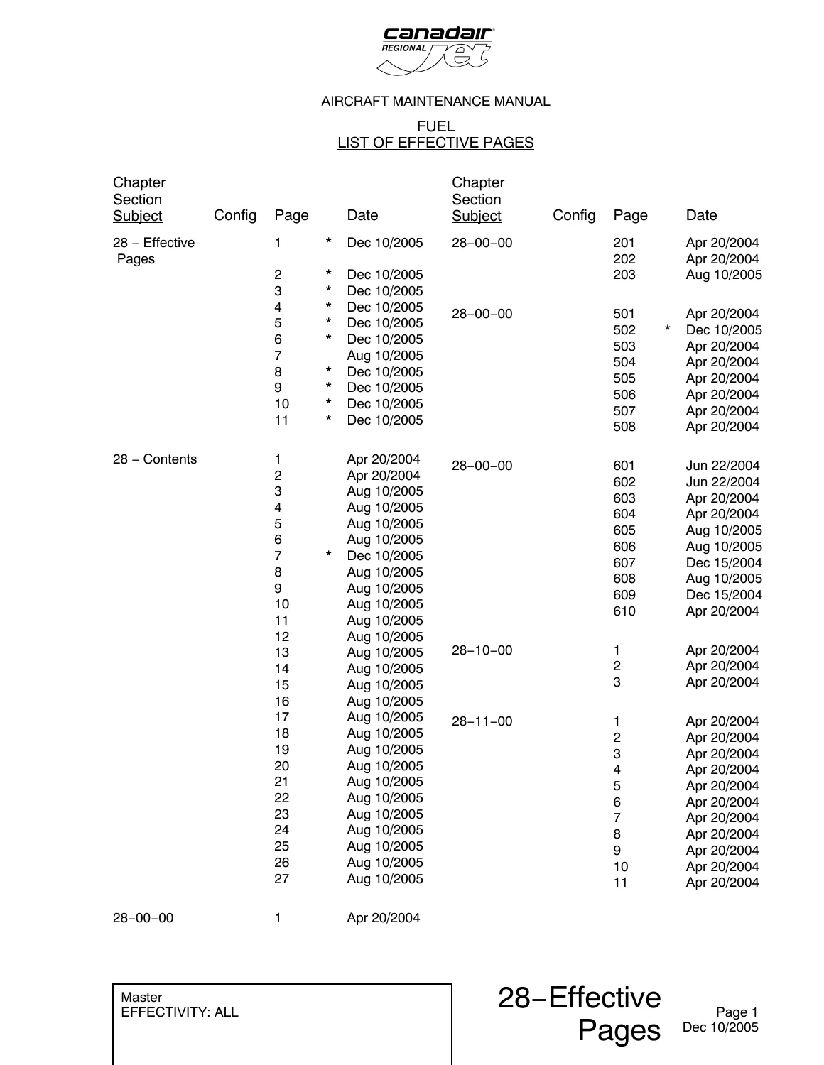
Official factory Aircraft Maintenance Manual (AMM) Chapter 28 Fuel for the Canadair Regional Jet. Provides comprehensive maintenance practices, operational testing, removal/installation, inspection criteria, and schematics for storage, vent, distribution, and crossflow systems across 868 pages.
Description
Canadair Regional Jet Aircraft Maintenance Manual Chapter 28 Fuel System Overview
The Canadair Regional Jet Aircraft Maintenance Manual Chapter 28 Fuel System is the definitive technical authority for line technicians, MRO engineers, and flight line specialists servicing the complete fuel storage, transfer, and management architectures of the Canadair Regional Jet fleet. Covering all aircraft effectivities, this 868-page factory manual chapter details rigorous maintenance practices, component removal and installation procedures, leak rate classifications, contamination testing protocols, and full-system operational checks. Built directly from engineering data, this manual ensures uncompromised safety compliance, accurate defect troubleshooting, and standard airworthiness maintenance across all operational environments.
File Details
- Document Title: Canadair Regional Jet Aircraft Maintenance Manual – Chapter 28 Fuel
- Manual Type: Aircraft Maintenance Manual (AMM) Chapter
- Brand / Manufacturer: Canadair
- Equipment Model: Canadair Regional Jet
- ATA Chapter: Chapter 28 (Fuel)
- Revision Date: December 10, 2005 (incorporating revisions from April 20, 2004, and August 10, 2005)
- Language: English
- Page Count: 868 pages
- File Format: Adobe PDF
- Serial Effectivity: ON A/C ALL (with specific subtask effectivities covering serial blocks 7003 through 7990 and 8000 through 8068)
Chapters Covered
- 28-00-00 Fuel System – General
- Description and Operation (Storage, Distribution, and Indicating Systems)
- Maintenance Practices (Fuel Safety Precautions – General, Health, Electrical, Tools, and Contamination)
- Adjustment/Test (Operational Test of the Fuel System, EICAS Synoptic Verification, Fire Switch Interfaces)
- Inspection/Check (Water Contamination Check; Spectrochemical Hydraulic Fluid Contamination Analysis)
- 28-10-00 Storage System
- Description and Operation (Fuel Tank Architecture, Ram Air Vent System, Multi-Function Transfer System)
IMAGES PREVIEW
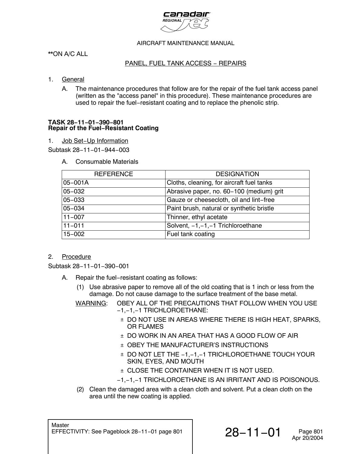
- 28-11-00 Fuel Tank System
- Description and Operation (Main Wet-Wing Tanks, Center Wing Box Tank, Composite Collector Tanks, Restrictors, Balancing Pipes, Drain Valves)
- Maintenance Practices (Tank Entry Preparation, Fuel Fume Removal, Gas Detector Monitoring, Biobor JF and Kathon FP 1.5 Biocide Treatments)
- Inspection/Check (Exterior Checks, In-Tank LRU Sealant Inspection, Critical Bonding Jumpers DLRO Testing, Air Pressurization, Fuel Leak Rate Classification)
- Repairs (Fuel Tank Seal Repair)
- 28-11-01 Fuel Tank Access Panel
- Removal and Installation (Honeycomb Core and Aluminum Lower Skin Access Panels)
- Inspection and Check (Damage Checks, Gasket Integrity, Wing Fastener Detailed Visual Checks)
- Repairs (Fuel-Resistant Coating Touch-Up, Phenolic Strip Adhesive Replacement)
- 28-11-03 Collector Tank (Removal, Fitting Teardown, Gasket Replacement, and Installation)
- 28-11-05 Collector Tank Check Valve (Flapper Valve Removal/Installation and 2-Hour Fuel Head Functional Leak Test)
- 28-11-07 One-Way Flow Valve (Removal and Installation across Wing Stations WS85.5, WS148.0, and WS220.0)
- 28-11-13 Water Drain Valve (Preformed Packing In-Situ Replacement, Valve Body and Housing Removal/Installation)
- 28-11-14 Fuel Drain Valve (Center and Main Tank Poppet Valve Removal and Installation)
- 28-11-17 Center Tank Gravity Fuel Feed Filler Installation (Scupper, Filler Neck, Adapter, and Filler-Cap O-Ring Checks)
- 28-12-00 Vent System
- Description and Operation (Main and Center Tank Overpressure Relief Valves, Purge Check Valves, Bipetal Flapper Valves, Vent Tubing, Shrouds)
- 28-12-01 Main Tank Relief Valve (Wing-Tip Relief Valve Removal/Installation and Manual Override Operational Test)
- 28-12-02 Center Tank Relief Valve (Sleeve, Transition Tube, Removal/Installation, and Operational Check)
- 28-12-04 Vent-Line-Purge Check Valve (Aft Scavenge Purge Line Removal and Installation)
- 28-12-06 Vent Line Flapper Check Valve (Bipetal Flapper Valve and Forward Vent-Tube Assembly Removal and Installation)
- 28-12-10 Fuel Tank Vent and Fuel Line Shrouds (Pressure Box Assembly and Shroud Drain Fitting Leak Testing)
- 28-13-00 Transfer System
- Description and Operation (Motive Flow Transfer Ejector Pumps, Scavenge Ejectors, Gravity Crossflow SOVs, Power Crossflow Network, Flight Compartment Controls)
- Adjustment/Test (Manual and Automatic Crossflow Operational Test)
As a whole, this manual gives line and base technicians an exhaustive standard for maintaining and recertifying the Canadair Regional Jet fuel systems. Every procedure contains complete consumable material lists, part replacement tables, required special tooling references, and precise mechanical torque values, ensuring reliable troubleshooting and compliance with continuous airworthiness requirements.
Comprehensive Storage Architecture & Fuel Management
The fuel storage architecture of the Canadair Regional Jet employs an integral wet-wing configuration comprising two main wing tanks and a center wing box tank, supplemented by dual composite collector tanks. Fuel continuously feeds the engines via motive-flow-operated primary ejectors, backed up by electric boost pumps seated inside self-sealing canisters. Automated crossflow and center-tank transfer functions are orchestrated by the fuel system computer. Center tank fuel is migrated to the main tanks through transfer ejector pumps that actuate when main tank levels fall below 93 percent and shut off when levels reach 97 percent. In the event of a lateral fuel imbalance exceeding 200 pounds (91 kg), the fuel computer commands the auxiliary power unit (APU) pump and dedicated crossflow shutoff valves to restore lateral balance automatically, terminating when the lighter tank exceeds the other by 50 pounds.
Complete Bookmarks
The complete bookmarks in the “Canadair Regional Jet Aircraft Maintenance Manual Chapter 28 Fuel System” are as follows:
+Chapter 28
+Section 00p. 41
+28-00-00p. 41
+1: FUEL SYSTEM – DESCRIPTION AND OPERATIONp. 41
+2. Descriptionp. 41
+201: FUEL SYSTEM – MAINTENANCE PRACTICESp. 43
+Task 28-00-00-910-801 Fuel Safety Precautionsp. 43
+501: FUEL SYSTEM – ADJUSTMENT/TESTp. 47
+Task 28-00-00-710-801 Operational Test of the Fuel Systemp. 47
+601: FUEL SYSTEM – INSPECTION/CHECKp. 55
+Task 28-00-00-210-801 Contamination Check of the Fuel System Components (Water)p. 55
+Task 28-00-00-210-802 Contamination Check of the Fuel System Components (Hydraulic Fluid)p. 57
+Section 10p. 65
+28-10-00p. 65
+1: STORAGE SYSTEM – DESCRIPTION AND OPERATIONp. 65
+2. Descriptionp. 65
+3. Operationp. 65
+Storage System – Block Diagramp. 67
+Section 11p. 69
+28-11-00p. 69
+1: FUEL TANK SYSTEM – DESCRIPTION AND OPERATIONp. 69
+2. Component Detailsp. 69
+Fuel Tank System – Component Location/Recognitionp. 75
+Fuel Tank System Movement Provisions – Component Location/Recognitionp. 76
+Fuel Tank System Drain Valves – Component Location/Recognitionp. 77
+Fuel Tank System – Schematicp. 78
+Fuel Tank System – Component Accessp. 79
+201: FUEL TANK SYSTEM – MAINTENANCE PRACTICESp. 81
+Task 28-11-00-840-801 Prepare Fuel Tank for Accessp. 81
+Task 28-11-00-840-802 Removal of Fuel Fumesp. 87
+Task 28-11-00-620-801 Biocide Treatment of the Fuel Tanksp. 89
+601: FUEL TANK SYSTEM – INSPECTION/CHECKp. 95
+Task 28-11-00-210-801 Visual Check of the Fuel Tank Exteriorp. 95
+Task 28-11-00-210-803 General Visual Inspection of the Fuel Access Panels and the Fuel and Water Drain Valvesp. 96
+Fuel Access Panels – General Visual Inspectionp. 97
+Fuel and Water Drain Valves – General Visual Inspectionp. 98
+Task 28-11-00-220-801 Detailed Inspection of the Sealant on In-Tank LRUsp. 99
+Sealant on In-Tank LRUs – Inspection/Checkp. 103
+Sealant on In-Tank LRUs – Inspection/Checkp. 115
+Sealant on In-Tank LRUs – Inspection/Checkp. 116
+Sealant on In-Tank LRUs – Inspection/Checkp. 117
+Sealant on In-Tank LRUs – Inspection/Checkp. 118
+Task 28-11-00-720-801 Functional Check of the Critical Bonding Jumpersp. 119
+Critical Bonding Jumper – Inspection/Checkp. 121
+Task 28-11-00-220-802 Detailed Inspection of the Critical Bonding Jumpersp. 123
+Critical Bonding Jumper – Inspection/Checkp. 125
+Task 28-11-00-780-802 Pressurization of the Fuel Tanks Using Shop Airp. 127
+Pressurization of the Fuel Tanks Using Shop Airp. 132
+Task 28-11-00-790-802 Leak Rate Check of the Fuel Tankp. 133
+Leak Classification of Fuel Tank – Inspection/Checkp. 136
+801: FUEL TANK – REPAIRSp. 137
+Task 28-11-00-390-801 Fuel-Tanks Seal Repairp. 137
+28-11-01p. 139
+401: PANEL, FUEL TANK ACCESS – REMOVAL/INSTALLATIONp. 139
+Task 28-11-01-000-801 Removal of the Honeycomb Access Panelp. 139
+Honeycomb Access Panel – Removal/Installationp. 142
+Task 28-11-01-400-801 Installation of the Honeycomb Access Panelp. 143
+Task 28-11-01-000-802 Removal of the Aluminum Access Panelp. 147
+Aluminum Access Panel – Removal/Installationp. 150
+Aluminum Access Panel – Removal/Installationp. 151
+Task 28-11-01-400-802 Installation of the Aluminum Access Panelp. 152
+601: PANEL, FUEL TANK ACCESS – INSPECTION/CHECKp. 159
+Task 28-11-01-210-801 Damage Check of the Honeycomb Access Panelp. 159
+Honeycomb Access Panel – Inspection/Checkp. 161
+Task 28-11-01-210-802 Damage Check of the Aluminum Access Panelp. 162
+Aluminum Access Panel – Inspection/Checkp. 164
+Task 28-11-01-220-801 Detailed Inspection of the Fuel Access-Panels and the Fuel and Water Drain Valves and Fastenersp. 165
+Fuel Access-Panels and the Fuel and Water Drain Valves and Fasteners – Inspection/Checkp. 166
+801: PANEL, FUEL TANK ACCESS – REPAIRSp. 167
+Task 28-11-01-390-801 Repair of the Fuel-Resistant Coatingp. 167
+Task 28-11-01-960-801 Replacement of the Phenolic Stripp. 169
+28-11-03p. 171
+401: TANK, COLLECTOR – REMOVAL/INSTALLATIONp. 171
+Task 28-11-03-000-801 Removal of the Collector Tankp. 171
+Collector Tank – Removal/Installationp. 174
+Collector Tank Fittings – Removal/Installationp. 175
+Task 28-11-03-400-801 Installation of the Collector Tankp. 176
+28-11-05p. 181
+401: CHECK VALVE, COLLECTOR TANK – REMOVAL/INSTALLATIONp. 181
+Task 28-11-05-000-801 Removal of the Collector Tank Check Valvep. 181
+Collector Tank Check Valve – Removal/Installationp. 183
+Task 28-11-05-400-801 Installation of the Collector Tank Check Valvep. 184
+501: COLLECTOR TANK CHECK VALVE – ADJUSTMENT/TESTp. 187
+Task 28-11-05-720-801 Functional Test of the Collector Tank Check Valvep. 187
+Collector Tank Check-Valve – Functional Testp. 190
+28-11-07p. 191
+401: VALVE, ONE-WAY FLOW – REMOVAL/INSTALLATIONp. 191
+Task 28-11-07-000-801 Removal of the One-Way Flow Valvep. 191
+One-Way Flow Valve – Removal/Installationp. 193
+Task 28-11-07-400-801 Installation of the One-Way Flow Valvep. 194
+28-11-13p. 197
+201: VALVE, WATER DRAIN – MAINTENANCE PRACTICESp. 197
+Task 28-11-13-960-801 Replacement of the Preformed Packingp. 197
+Water Drain Valve – Maintenance Practicesp. 199
+401: VALVE, WATER DRAIN – REMOVAL/INSTALLATIONp. 201
+Task 28-11-13-000-801 Removal of the Water Drain Valvep. 201
+Water Drain Valve – Removal/Installationp. 203
+Task 28-11-13-400-801 Installation of the Water Drain Valvep. 204
+Task 28-11-13-000-802 Removal of the Water Drain Housingp. 206
+Wing Tank Water Drain Housing – Removal/Installationp. 209
+Collector Tank Water Drain Housing – Removal/Installationp. 210
+Boost Pump Water Drain Housing – Removal/Installationp. 211
+Task 28-11-13-400-802 Installation of the Water Drain Housingp. 212
+28-11-14p. 217
+401: VALVE, FUEL DRAIN – REMOVAL/INSTALLATIONp. 217
+Task 28-11-14-000-801 Removal of the Fuel Drain Valvep. 217
+Fuel Drain Valve – Removal/Installationp. 219
+Task 28-11-14-400-801 Installation of the Fuel Drain Valvep. 220
+28-11-17p. 223
+401: FILLER INSTALLATION, GRAVITY FUEL FEED, CENTER TANK – REMOVAL/INSTALLATIONp. 223
+Task 28-11-17-000-802 Removal of the Center-Tank Gravity-Fuel-Feed-Filler Installationp. 223
+Center-Tank Gravity-Fuel-Feed Filler-Cap – Removal/Installationp. 225
+Task 28-11-17-400-802 Installation of the Center-Tank Gravity-Fuel-Feed-Filler Installationp. 226
+601: FUEL FILLER-CAP O RING – INSPECTION/CHECKp. 229
+Task 28-11-17-210-801 Visual Check of the Fuel Filler-Cap "O" Ringp. 229
+Fuel Filler-Cap "O" Ring – Visual Checkp. 230
+Section 12p. 231
+28-12-00p. 231
+1: VENT SYSTEM – DESCRIPTION AND OPERATIONp. 231
+2. Component Detailsp. 231
+Vent System – Component Location/Recognitionp. 236
+Vent System – Component Location/Recognitionp. 237
+Vent System – Schematicp. 238
+Vent System-Schematicp. 239
+Vent System – Component Accessp. 240
+28-12-01p. 241
+401: VALVE, MAIN TANK RELIEF – REMOVAL/INSTALLATIONp. 241
+Task 28-12-01-000-801 Removal of the Main Tank Relief Valvep. 241
+Main Tank Relief Valve – Removal/Installationp. 243
+Task 28-12-01-400-801 Installation of the Main Tank Relief Valvep. 244
+501: VALVE, MAIN TANK RELIEF – ADJUSTMENT/TESTp. 247
+Task 28-12-01-710-801 Operational Test of the Main Tank Relief Valvep. 247
+28-12-02p. 249
+401: VALVE, CENTER TANK RELIEF – REMOVAL/INSTALLATIONp. 249
+Task 28-12-02-000-801 Removal of the Center Tank Relief Valvep. 249
+Center Tank Relief Valve – Removal/Installationp. 251
+Task 28-12-02-400-801 Installation of the Center Tank Relief Valvep. 252
+501: VALVE, CENTER TANK RELIEF – ADJUSTMENT/TESTp. 255
+Task 28-12-02-710-801 Operational Test of the Center-Tank Relief Valvep. 255
+28-12-04p. 257
+401: CHECK VALVE, VENT-LINE-PURGE – REMOVAL/INSTALLATIONp. 257
+Task 28-12-04-000-801 Removal of the Vent-Line-Purge Check Valvep. 257
+Vent Line Purge Check Valve – Removal/Installationp. 260
+Right Vent Line Purge Check Valve – Removal/Installationp. 261
+Left Vent Line Purge Check Valve – Removal/Installationp. 262
+Task 28-12-04-400-801 Installation of the Vent-Line-Purge Check Valvep. 263
+28-12-06p. 267
+401: VALVE, VENT LINE, FLAPPER CHECK – REMOVAL/INSTALLATIONp. 267
+Task 28-12-06-000-801 Removal of the Flapper Valvep. 267
+Forward Vent-Tube Assembly – Removal/Installationp. 271
+Forward Vent-Tube Assembly – Removal/Installationp. 272
+Flapper Valve – Removal/Installationp. 273
+Task 28-12-06-400-801 Installation of the Flapper Valvep. 274
+28-12-10p. 279
+501: FUEL TANK VENT AND FUEL LINE SHROUDS – LEAK TESTp. 279
+Task 28-12-10-790-801 Pressure Leak Test of the Fuel Tank Vent and Fuel Line Shroudsp. 279
+Fuel Line Shrouds – Pressure Leak Testp. 282
+Section 13p. 283
+28-13-00p. 283
+1: TRANSFER SYSTEM – DESCRIPTION AND OPERATIONp. 283
+2. Component Detailsp. 283
+Transfer System – Component Location/Recognitionp. 289
+Transfer System Crossflow – Component Location/Recognitionp. 290
+Transfer System Controls – Component Location/Recognitionp. 291
+Transfer System – Schematicp. 292
+Auto/Manual Power Fuel Crossflow Function – Electrical Schematicp. 293
+Gravity Fuel Crossflow and Fuel Transfer Functions – Electrical Schematicp. 294
+Transfer System – Component Accessp. 295
+501: TRANSFER SYSTEM – ADJUSTMENT/TESTp. 297
+Task 28-13-00-710-801 Operational Test of the Fuel Manual-Crossflow Systemp. 297
+28-13-01p. 301
+401: PUMP, TRANSFER EJECTOR – REMOVAL/INSTALLATIONp. 301
+Task 28-13-01-000-801 Removal of the Transfer Ejector Pumpp. 301
+Transfer Ejector Pump – Removal/Installationp. 303
+Task 28-13-01-400-801 Installation of the Transfer Ejector Pumpp. 304
+501: PUMP, TRANSFER EJECTOR – ADJUSTMENT/TESTp. 307
+Task 28-13-01-710-801 Operational Test of the Transfer Ejector Pumpp. 307
+28-13-16p. 309
+401: VALVE, GRAVITY CROSSFLOW SHUTOFF – REMOVAL/INSTALLATIONp. 309
+Task 28-13-16-000-801 Removal of the Gravity Crossflow Shutoff Valvep. 309
+Gravity Crossflow Shutoff Valve – Removal/Installationp. 313
+Gravity Crossflow Shutoff Valve – Removal/Installationp. 314
+Task 28-13-16-400-801 Installation of the Gravity Crossflow Shutoff Valvep. 315
+Task 28-13-16-000-802 Removal of the Gravity Crossflow Shutoff Valve Electrical Actuator.p. 319
+Gravity Crossflow Shutoff Valve Electrical Actuator – Removal/Installationp. 321
+Task 28-13-16-400-802 Installation of the Gravity Crossflow Shutoff Valve Electrical Actuatorp. 322
+501: VALVE, GRAVITY CROSSFLOW SHUTOFF – ADJUSTMENT/TESTp. 325
+Task 28-13-16-710-801 Operational Test of the Gravity Crossflow Shutoff Valvep. 325
+28-13-19p. 327
+401: CHECK VALVE, CROSSFLOW – REMOVAL/INSTALLATIONp. 327
+Task 28-13-19-000-801 Removal of the Crossflow Check Valvep. 327
+Crossflow Check Valve – Removal/Installationp. 329
+Task 28-13-19-400-801 Installation of the Crossflow Check Valvep. 330
+28-13-22p. 333
+401: PUMP, AFT SCAVENGE EJECTOR – REMOVAL/INSTALLATIONp. 333
+Task 28-13-22-000-801 Removal of the Aft Scavenge Ejector Pumpp. 333
+Aft Scavenge Ejector Pump – Removal/Installationp. 335
+Task 28-13-22-400-801 Installation of the Aft Scavenge Ejector Pumpp. 336
+501: PUMP, AFT SCAVENGE EJECTOR – ADJUSTMENT/TESTp. 339
+Task 28-13-22-710-801 Operational Test of the Aft Scavenge Ejector Pumpp. 339
+28-13-28p. 341
+401: MANIFOLD, GRAVITY FEED – REMOVAL/INSTALLATIONp. 341
+Task 28-13-28-000-801 Removal of the Gravity Feed Manifoldp. 341
+Gravity Feed Manifold – Removal/Installationp. 343
+Task 28-13-28-400-801 Installation of the Gravity Feed Manifoldp. 344
+28-13-31p. 347
+401: SWITCH/LIGHT, FUEL CROSSFLOW – REMOVAL/INSTALLATIONp. 347
+Task 28-13-31-000-801 Removal of the Fuel Crossflow Switch/Lightp. 347
+Fuel Crossflow Switch/Light – Removal/Installationp. 349
+Task 28-13-31-400-801 Installation of the Fuel Crossflow Switch/Lightp. 350
+28-13-43p. 353
+401: VALVE, FUEL TRANSFER SHUTOFF – REMOVAL/INSTALLATIONp. 353
+Task 28-13-43-000-801 Removal of the Fuel-Transfer Shutoff Valvep. 353
+Fuel-Transfer Shutoff Valve – Removal/Installationp. 357
+Fuel-Transfer Shutoff Valve – Removal/Installationp. 358
+Task 28-13-43-400-801 Installation of the Fuel-Transfer Shutoff Valvep. 359
+501: VALVE, FUEL TRANSFER SHUTOFF – ADJUSTMENT/TESTp. 365
+Task 28-13-43-710-801 Operational Test of the Fuel-Transfer Shutoff Valvep. 365
+28-13-45p. 369
+401: VALVE, FUEL CROSSFLOW SHUTOFF – REMOVAL/INSTALLATIONp. 369
+Task 28-13-45-000-801 Removal of the Fuel Crossflow Shutoff Valvep. 369
+Fuel Crossflow Shutoff Valve – Removal/Installationp. 372
+Fuel Crossflow Shutoff Valve – Removal/Installationp. 373
+Task 28-13-45-400-801 Installation of the Fuel Crossflow Shutoff Valvep. 374
+501: VALVE, FUEL CROSSFLOW SHUTOFF – ADJUSTMENT/TESTp. 379
+Task 28-13-45-710-801 Operational Test of the Fuel Crossflow Shutoff Valvep. 379
+Section 20p. 381
+28-20-00p. 381
+1: DISTRIBUTION SYSTEM – DESCRIPTION AND OPERATIONp. 381
+2. Descriptionp. 381
+3. Operationp. 381
+Distribution System – Block Diagramp. 384
+28-20-01p. 385
+401: SHROUD, FUEL LINES – REMOVAL/INSTALLATIONp. 385
+Task 28-20-01-000-801 Removal of the Fuel Lines Shroud (FS559.00 to FS621.00)p. 385
+Fuel Shroud and Fuel Lines Assemblyp. 396
+APU Fuel-Feed Assemblyp. 397
+Cross Adaptor Assemblyp. 398
+Left/Right Engine Fuel-Feed Assemblyp. 400
+Common Fuel-Feed Assembly – Removal/Installationp. 401
+Common Fuel-Feed Assembly – Removal/Installationp. 404
+Task 28-20-01-400-801 Installation of the Fuel Lines Shroud (FS559 to 621)p. 407
+Tightening Sequence for Transition Shroud Screwsp. 427
+501: SHROUD, FUEL LINE-ADJUSTMENT/TESTp. 429
+Task 28-20-01-780-801 Pressure and Blockage Test of the Fuel Line Shroud Forward of FS 621.00p. 429
+Fuel Line Shroud – Adjustment/Testp. 431
+Task 28-20-01-780-802 Pressure and Blockage Test of the Engine Fuel-Feed Linep. 432
+Center Tank Fuel – Feed Tubesp. 437
+Engine Pylon Fuel – Feed Tubesp. 438
+Task 28-20-01-780-803 Pressure and Blockage Test of the Motive Flow-Fuel Feed Linep. 439
+Task 28-20-01-780-804 Pressure and Blockage Test of the APU Fuel-Feed Linep. 445
+APU Fuel – Feed to FCU Connectionp. 450
+28-20-05p. 451
+401: TUBE, SHROUD DRAIN, PRESSURE BOX – REMOVAL/INSTALLATIONp. 451
+Task 28-20-05-000-801 Removal of the Pressure-Box-Shroud-Drain Tubep. 451
+Pressure-Box-Shroud-Drain Tube – Removal/Installationp. 453
+Pressure-Box-Shroud-Drain Tube – Removal/Installationp. 454
+Task 28-20-05-400-801 Installation of the Pressure-Box-Shroud-Drain Tubep. 455
+Section 21p. 459
+28-21-00p. 459
+1: ENGINE FUEL FEED SYSTEM – DESCRIPTION AND OPERATIONp. 459
+2. Component Detailsp. 459
+Engine Fuel Feed System – Component Location/Recognitionp. 461
+Engine Fuel Feed System – Schematicp. 462
+Engine Fuel Feed System – Component Accessp. 463
+501: ENGINE FUEL FEED SYSTEM – ADJUSTMENT/TESTp. 465
+Task 28-21-00-790-801 Leak Test of the Engine Fuel-Feed Tubesp. 465
+28-21-01p. 469
+401: PUMP, PRIMARY EJECTOR – REMOVAL/INSTALLATIONp. 469
+Task 28-21-01-000-801 Removal of the Primary Ejector Pumpp. 469
+Primary Ejector Pump – Removal/Installationp. 471
+Task 28-21-01-400-801 Installation of the Primary Ejector Pumpp. 472
+501: PUMP, PRIMARY EJECTOR – ADJUSTMENT/TESTp. 475
+Task 28-21-01-710-801 Operational Test of the Primary Ejector Pumpp. 475
+28-21-04p. 477
+401: CHECK VALVE, FUEL FEED LINE – REMOVAL/INSTALLATIONp. 477
+Task 28-21-04-000-801 Removal of the Fuel Feed Line Check Valvep. 477
+Fuel Feed Line Check Valve – Removal/Installationp. 479
+Task 28-21-04-400-801 Installation of the Fuel Feed Line Check Valvep. 480
+501: CHECK VALVE, ENGINE-FUEL-FEED LINE – ADJUSTMENT/TESTp. 483
+Task 28-21-04-710-801 Operational Test of the Engine-Fuel-Feed-Line Check Valvep. 483
+28-21-07p. 487
+401: VALVE, ENGINE FUEL FEED SHUTOFF – REMOVAL/INSTALLATIONp. 487
+Task 28-21-07-000-801 Removal of the Engine-Fuel-Feed Shutoff Valvep. 487
+Engine-Fuel-Feed Shutoff Valve – Removal/Installationp. 489
+Task 28-21-07-400-801 Installation of the Engine-Fuel-Feed Shutoff Valvep. 490
+Task 28-21-07-000-802 Removal of the Engine-Fuel-Feed Shutoff Valve Electrical Actuatorp. 492
+Engine Fuel Feed Shutoff Valve Electrical Actuator – Removal/Installationp. 494
+Task 28-21-07-400-802 Installation of the Engine-Fuel-Feed Shutoff Valve Electrical Actuatorp. 495
+501: VALVE, ENGINE FUEL FEED SHUTOFF – ADJUSTMENT/TESTp. 497
+Task 28-21-07-710-801 Operational Test of the Engine-Fuel-Feed Shutoff Valvep. 497
+Engine-fuel-feed Shutoff Valve – Adjustment/Testp. 502
+Task 28-21-07-710-802 Operation Test of the Engine-Fuel-Shutoff-Valve Position Indicatorsp. 503
+28-21-13p. 505
+401: SHROUD, ENGINE FUEL FEED – REMOVAL/INSTALLATIONp. 505
+Task 28-21-13-000-801 Removal of the Shroud and Engine-Fuel-Feed Tube from FS621.00 to the Engine Pylon Firewallp. 505
+Shroud, Engine Fuel-Feed Line – Removal/Installationp. 509
+Task 28-21-13-400-801 Installation of the Shroud and the Engine Fuel-Feed Line from FS621.00 to the Engine Pylon Firewallp. 512
+501: SHROUDS, ENGINE FEED and ABOVE WING- ADJUSTMENT/TESTp. 519
+Task 28-21-13-780-801 Pressure and Blockage Test of the Engine Fuel-Feed Shroud, FS 621.00 to the Engine Pylon Firewallp. 519
+Engine Fuel-Feed Shroud – Adjustment/Testp. 522
+Task 28-21-13-780-802 Pressure and Leak Test of the Above Wing Fuel-Feed Shrouds at FS 501.4, the Motive Flow Shrouds at FS 503.9 and the APU Shroud at FS 506.4p. 523
+Engine Fuel Feed Drain – Adjustment/Testp. 525
+Section 22p. 527
+28-22-00p. 527
+1: MOTIVE FLOW SYSTEM – DESCRIPTION AND OPERATIONp. 527
+2. Component Detailsp. 527
+Motive Flow System – Component Location/Recognitionp. 529
+Motive Flow System – Schematicp. 530
+Motive Flow System – Component Accessp. 531
+28-22-01p. 533
+401: FILTER, WASH – REMOVAL/INSTALLATIONp. 533
+Task 28-22-01-000-801 Removal of the Wash Filterp. 533
+Wash Filter – Removal/Installationp. 535
+Task 28-22-01-400-801 Installation of the Wash Filterp. 536
+28-22-04p. 539
+401: CHECK VALVE, MOTIVE FLOW – REMOVAL/INSTALLATIONp. 539
+Task 28-22-04-000-801 Removal of the Motive Flow Check Valvep. 539
+Motive Flow Check Valve – Removal/Installationp. 541
+Task 28-22-04-400-801 Installation of the Motive Flow Check Valvep. 542
+28-22-07p. 545
+401: VENTURI – REMOVAL/INSTALLATIONp. 545
+Task 28-22-07-000-801 Removal of the Venturip. 545
+Venturi – Removal/Installationp. 547
+Task 28-22-07-400-801 Installation of the Venturip. 548
+28-22-09p. 551
+401: LINES, MOTIVE FLOW – REMOVAL/INSTALLATIONp. 551
+Task 28-22-09-000-801 Removal of the Motive Flow Linesp. 551
+Motive Flow Lines – Removal/Installationp. 553
+Task 28-22-09-400-801 Installation of the Motive Flow Linesp. 554
+501: LINES, MOTIVE FLOW – ADJUSTMENT/TESTp. 557
+Task 28-22-09-780-801 Pressure Blockage Test and Leak Test of the Motive Flow Linesp. 557
+Motive Flow Lines – Adjustment/Testp. 560
+28-22-11p. 561
+501: SHROUD, MOTIVE FLOW – ADJUSTMENT/TESTp. 561
+Task 28-22-11-780-801 Pressure and Blockage Test of the Motive Flow Shroud, FS 621.00 to the Engine Pylon Firewallp. 561
+Motive Flow Shroud – Adjustment/Testp. 564
+Section 23p. 565
+28-23-00p. 565
+1: STANDBY FUEL FEED SYSTEM – DESCRIPTION AND OPERATIONp. 565
+2. Component Detailsp. 565
+Standby Fuel Feed System – Component Location/Recognitionp. 568
+Standby Fuel Feed System Controls – Component Location/Recognitionp. 569
+Standby Fuel Feed System – Schematicp. 570
+Standby Fuel Feed System – Component Accessp. 571
+28-23-01p. 573
+401: PUMP, ELECTRIC BOOST – REMOVAL/INSTALLATIONp. 573
+Task 28-23-01-000-801 Removal of the Electric Boost Pumpp. 573
+Electric Boost Pump – Removal/Installationp. 575
+Task 28-23-01-400-801 Installation of the Electric Boost Pumpp. 576
+501: PUMP, ELECTRIC BOOST – ADJUSTMENT/TESTp. 579
+Task 28-23-01-710-801 Operational Test of the Electric Boost Pumpp. 579
+28-23-03p. 581
+401: CANISTER, BOOST PUMP – REMOVAL/INSTALLATIONp. 581
+Task 28-23-03-000-801 Removal of the Boost Pump Canisterp. 581
+Boost Pump Canister – Removal/Installationp. 586
+Boost Pump Canisterp. 587
+Boost Pump Canister – Removal/Installationp. 588
+Task 28-23-03-400-801 Installation of the Boost Pump Canisterp. 589
+28-23-04p. 601
+401: SWITCH/LIGHT, BOOST PUMP – REMOVAL/INSTALLATIONp. 601
+Task 28-23-04-000-801 Removal of the Boost Pump Switch/Lightp. 601
+Boost Pump Switch/Light – Removal/Installationp. 603
+Task 28-23-04-400-801 Installation of the Boost Pump Switch/Lightp. 604
+28-23-07p. 607
+401: CHECK VALVE, STANDBY FUEL-FEED LINE – REMOVAL/INSTALLATIONp. 607
+Task 28-23-07-000-801 Removal of the Standby-Fuel-Feed-Line Check Valvep. 607
+Standby-Fuel-Feed-Line Check Valve – Removal/Installationp. 610
+Task 28-23-07-400-801 Installation of the Standby-Fuel-Feed-Line Check Valvep. 612
+501: CHECK VALVE, STANDBY FUEL FEED – ADJUSTMENT/TESTp. 615
+Task 28-23-07-710-801 Operational Test of the Standby-Fuel-Feed Check Valvep. 615
+Section 24p. 619
+28-24-00p. 619
+1: AUXILIARY POWER UNIT (APU) FUEL FEED SYSTEM – DESCRIPTION AND OPERATIONp. 619
+2. Component Detailsp. 619
+APU Fuel Feed System – Component Location/Recognitionp. 622
+APU Fuel Feed System – Schematicp. 623
+APU Fuel Feed System – Component Accessp. 624
+28-24-01p. 625
+401: PUMP, AUXILIARY POWER UNIT (APU) FUEL – REMOVAL/INSTALLATIONp. 625
+Task 28-24-01-000-801 Removal of the APU Fuel Pump Cartridgep. 625
+APU Fuel-Pump Cartridge – Removal/Installationp. 627
+Task 28-24-01-400-801 Installation of the APU Fuel Pump Cartridgep. 628
+Task 28-24-01-000-802 Removal of the APU Fuel Pump Canisterp. 630
+APU Fuel Pump Canister – Removal/Installationp. 632
+Task 28-24-01-400-802 Installation of the APU Fuel Pump Canisterp. 633
+501: PUMP, AUXILIARY POWER UNIT (APU) FUEL – ADJUSTMENT/TESTp. 637
+Task 28-24-01-710-801 Operational Test of the APU Fuel Pumpp. 637
+28-24-07p. 639
+401: CHECK VALVE, AUXILIARY POWER UNIT (APU) FEED LINE – REMOVAL/INSTALLATIONp. 639
+Task 28-24-07-000-801 Removal of the APU Feed Line Check Valvep. 639
+APU Feed Line Check Valve – Removal/Installationp. 641
+Task 28-24-07-400-801 Installation of the APU Feed Line Check Valvep. 642
+28-24-10p. 645
+401: CHECK VALVE, AUXILIARY POWER UNIT (APU) NEGATIVE-GRAVITY FEED – REMOVAL/INSTALLATIONp. 645
+Task 28-24-10-000-801 Removal of the APU Negative-Gravity Feed Check Valvep. 645
+APU Negative-Gravity Feed Check Valve – Removal/Installationp. 647
+Task 28-24-10-400-801 Installation of the APU Negative-Gravity Feed Check Valvep. 648
+28-24-23p. 649
+401: SHROUD, AUXILIARY POWER UNIT (APU) FEED – REMOVAL/INSTALLATIONp. 649
+Task 28-24-23-000-801 Removal of the APU Feed Shroudp. 649
+APU Feed Shroud – Removal/Installationp. 652
+Task 28-24-23-400-801 Installation of the APU Feed Shroudp. 653
+501: SHROUD, AUXILIARY POWER UNIT (APU) FEED – ADJUSTMENT/TESTp. 657
+Task 28-24-23-780-801 Pressure and Blockage Test of the APU Feed Shroudp. 657
+APU Feed Shroud – Adjustment/Testp. 660
+APU Feed Shroud – Adjustment/Testp. 661
+28-24-25p. 663
+401: VALVE, AUXILIARY POWER UNIT (APU) FUEL FEED SHUTOFF – REMOVAL/INSTALLATIONp. 663
+Task 28-24-25-000-801 Removal of the APU Fuel Feed Shutoff Valvep. 663
+APU Fuel Feed Shutoff Valve – Removal/Installationp. 665
+Task 28-24-25-400-801 Installation of the APU Fuel Feed Shutoff Valvep. 666
+Task 28-24-25-000-802 Removal of the APU Fuel Feed Shutoff Valve Electrical Actuatorp. 668
+APU Fuel Feed Shutoff Valve Electrical Actuator – Removal/Installationp. 670
+Task 28-24-25-400-802 Installation of the APU Fuel Feed Shutoff Valve Electrical Actuatorp. 671
+501: VALVE, AUXILIARY POWER UNIT (APU) FUEL FEED SHUTOFF – ADJUSTMENT/TESTp. 673
+Task 28-24-25-710-801 Operational Test of the APU Fuel-Feed Shutoff-Valvep. 673
+Task 28-24-25-710-802 Operation Test of APU Fuel-Feed Shutoff-Valve Position-Indicatorp. 676
+Task 28-24-25-790-801 Leak Test of the APU Fuel-Feed Shutoff-Valvep. 678
+601: VALVE, AUXILIARY POWER UNIT (APU) FUEL FEED SHUTOFF – INSPECTION/CHECKp. 681
+Task 28-24-25-200-801 Internal Leak Checkp. 681
+APU Fuel Feed Shutoff Valve – Inspection/Checkp. 685
+Section 25p. 687
+28-25-00p. 687
+1: PRESSURE REFUEL/DEFUEL SYSTEM – DESCRIPTION AND OPERATIONp. 687
+2. Component Detailsp. 688
+Pressure Refuel/Defuel System Refueling – Component Location/Recognitionp. 697
+Pressure Refuel/Defuel System Refueling – Component Location/Recognitionp. 698
+Pressure Refuel/Defuel System – Component Location/Recognitionp. 699
+Pressure Refuel/Defuel System – Schematicp. 700
+Pressure Refuel/Defuel System – Electrical Schematicp. 701
+Pressure Refuel/Defuel System – Component Accessp. 702
+501: PRESSURE REFUEL/DEFUEL SYSTEM – ADJUSTMENT/TESTp. 703
+Task 28-25-00-710-801 Operational Test of the Refuel/Defuel Systemp. 703
+Pressure Refuel/Defuel System – Adjustment/Testp. 710
+Grounding of the Aircraft – Maintenance Practicesp. 711
+28-25-01p. 713
+401: ADAPTER, REFUELING – REMOVAL/INSTALLATIONp. 713
+Task 28-25-01-000-801 Removal of the Refueling Adapterp. 713
+Refueling Adapter – Removal/Installationp. 716
+Task 28-25-01-400-801 Installation of the Refueling Adapterp. 717
+28-25-04p. 721
+401: CHECK VALVE, REFUEL/DEFUEL – REMOVAL/INSTALLATIONp. 721
+Task 28-25-04-000-801 Removal of the Refuel/Defuel Check Valvep. 721
+Refuel/Defuel Check Valve – Removal/Installationp. 724
+Task 28-25-04-400-801 Installation of the Refuel/Defuel Check Valvep. 725
+28-25-07p. 727
+401: VALVE, REFUEL SHUTOFF – REMOVAL/INSTALLATIONp. 727
+Task 28-25-07-000-801 Removal of the Refuel Shutoff Valvep. 727
+Refuel Shutoff Valve – Removal/Installationp. 731
+Refuel Shutoff Valve – Removal/Installationp. 732
+Task 28-25-07-400-801 Installation of the Refuel Shutoff Valvep. 733
+28-25-13p. 739
+401: SENSOR, HIGH-LEVEL – REMOVAL/INSTALLATIONp. 739
+Task 28-25-13-000-801 Removal of the High-Level Sensorp. 739
+High-Level Sensor – Removal/Installationp. 742
+Task 28-25-13-400-801 Installation of the High-Level Sensorp. 743
+28-25-16p. 747
+401: PANEL, REFUEL/DEFUEL CONTROL – REMOVAL/INSTALLATIONp. 747
+Task 28-25-16-000-801 Removal of the Fuselage-Refuel/Defuel Control Panelp. 747
+Refuel/Defuel Control Panel – Removal/Installationp. 749
+Task 28-25-16-400-801 Installation of the Fuselage-Refuel/Defuel Control Panelp. 750
+Task 28-25-16-000-802 Removal of the Flight-Compartment-Refuel/Defuel Control Panelp. 752
+Flight Compartment Refuel/Defuel Control Panel – Removal/Installationp. 754
+Task 28-25-16-400-802 Installation of the Flight-Compartment-Refuel/Defuel Control Panelp. 755
+Section 31p. 757
+28-31-01p. 757
+401: PANEL, FUEL CONTROL – REMOVAL/INSTALLATIONp. 757
+Task 28-31-01-000-801 Removal of the FUEL Control Panelp. 757
+FUEL Control Panel – Removal/Installationp. 759
+Task 28-31-01-400-801 Installation of the FUEL Control Panelp. 760
+Section 40p. 763
+28-40-00p. 763
+1: FUEL INDICATING SYSTEM – DESCRIPTION AND OPERATIONp. 763
+2. Descriptionp. 763
+3. Operationp. 763
+Indicating System – Block Diagramp. 765
+Section 41p. 767
+28-41-00p. 767
+1: FUEL QUANTITY GAUGING SYSTEM – DESCRIPTION AND OPERATIONp. 767
+2. Component Detailsp. 767
+Fuel Quantity Gauging System – Component Location/Recognitionp. 770
+Fuel System Computer – Component Location/Recognitionp. 771
+Fuel Quantity Gauging System – Schematicp. 772
+Fuel Quantity Gauging System – Component Accessp. 773
+28-41-04p. 775
+401: PROBE, FUEL QUANTITY TRANSMITTER – REMOVAL/INSTALLATIONp. 775
+Task 28-41-04-000-801 Removal of the Fuel Quantity Transmitter Probep. 775
+Fuel Quantity Transmitter Probe – Removal/Installationp. 778
+Task 28-41-04-400-801 Installation of the Fuel Quantity Transmitter Probep. 779
+501: PROBES, FUEL QUANTITY TRANSMITTERS – ADJUSTMENT/TESTp. 783
+Task 28-41-04-720-801 Functional Test of the Fuel Quantity Transmitter Probesp. 783
+28-41-10p. 789
+401: INDICATOR, FUEL MAGNETIC LEVEL – REMOVAL/INSTALLATIONp. 789
+Task 28-41-10-400-804 Removal of the Fuel Magnetic Level Indicatorp. 789
+Fuel Magnetic Level Indicator – Removal/Installationp. 791
+Task 28-41-10-400-805 Installation of the Fuel Magnetic Level Indicatorp. 792
+28-41-16p. 795
+401: COMPUTER, FUEL SYSTEM – REMOVAL/INSTALLATIONp. 795
+Task 28-41-16-000-801 Removal of the Fuel System Computerp. 795
+Fuel System Computer – Removal/Installationp. 797
+Task 28-41-16-400-801 Installation of the Fuel System Computerp. 798
+501: COMPUTER, FUEL SYSTEM – ADJUSTMENT/TESTp. 801
+Task 28-41-16-740-801 Fuel Computer Bite Checkp. 801
+28-41-17p. 807
+401: FILTER, ELECTRONIC – REMOVAL/INSTALLATIONp. 807
+Task 28-41-17-000-801 Removal of the Fuel System Electronic Filterp. 807
+Electronic Filter – Removal / Installationp. 809
+Task 28-41-17-400-801 Installation of the Fuel System Electronic Filterp. 810
+28-41-19p. 813
+401: COMPENSATOR – REMOVAL/INSTALLATIONp. 813
+Task 28-41-19-000-801 Removal of the Compensatorp. 813
+Compensator – Removal/Installationp. 816
+Task 28-41-19-400-801 Installation of the Compensatorp. 817
+28-41-23p. 819
+401: ATTITUDE INDICATORS – REMOVAL/INSTALLATIONp. 819
+Task 28-41-23-000-801 Removal of the Attitude Indicatorsp. 819
+Attitude Indicators – Removal/Installationp. 821
+Attitude Indicators – Removal/Installationp. 822
+Task 28-41-23-400-801 Installation of the Attitude Indicatorsp. 823
+Section 42p. 827
+28-42-00p. 827
+1: FUEL WARNING SYSTEM – DESCRIPTION AND OPERATIONp. 827
+2. Component Detailsp. 827
+Fuel Warning System – Component Location/Recognitionp. 830
+Fuel Warning System – Schematicp. 831
+Fuel Warning System – Component Accessp. 832
+28-42-01p. 833
+401: PRESSURE SWITCH, BOOST PUMP – REMOVAL/INSTALLATIONp. 833
+Task 28-42-01-000-801 Removal of the Boost Pump Pressure Switchp. 833
+Boost Pump Pressure Switch – Removal/Installationp. 835
+Task 28-42-01-400-801 Installation of the Boost Pump Pressure Switchp. 836
+28-42-04p. 839
+401: PRESSURE SWITCH, ENGINE FUEL FEED – REMOVAL/INSTALLATIONp. 839
+Task 28-42-04-000-801 Removal of the Engine Fuel Feed Pressure Switchp. 839
+Engine Fuel Feed Pressure Switch – Removal/Installationp. 841
+Task 28-42-04-400-801 Installation of the Engine Fuel Feed Pressure Switchp. 842
+28-42-07p. 845
+401: PRESSURE SWITCH, SCAVENGE EJECTOR DIFFERENTIAL – REMOVAL/INSTALLATIONp. 845
+Task 28-42-07-000-801 Removal of the Scavenge Ejector Differential Pressure Switchp. 845
+Scavenge Ejector Differential Pressure Switch – Removal/Installationp. 847
+Task 28-42-07-400-801 Installation of the Scavenge Ejector Differential Pressure Switchp. 848
+28-42-10p. 851
+401: PRESSURE SWITCH, AUXILIARY POWER UNIT (APU) FUEL PUMP – REMOVAL/INSTALLATIONp. 851
+Task 28-42-10-000-801 Removal of the APU Fuel Pump Pressure Switchp. 851
+APU Fuel Pump Pressure Switch – Removal/Installationp. 854
+Task 28-42-10-400-801 Installation of the APU Fuel Pump Pressure Switchp. 855
+28-42-15p. 859
+401: SENSOR, FUEL TEMPERATURE – REMOVAL/INSTALLATIONp. 859
+Task 28-42-15-000-801 Removal of the Fuel Temperature Sensorp. 859
+Fuel Temperature Sensor – Removal/Installationp. 861
+Task 28-42-15-400-801 Installation of the Fuel Temperature Sensorp. 862
+501: SENSOR, FUEL TEMPERATURE – ADJUSTMENT/TESTp. 865
+Task 28-42-15-720-801 Functional Test of the Fuel Temperature Sensorp. 865
Strict Confined-Space Safety & Tank Entry Protocols
Working on commercial aircraft fuel cells requires rigid compliance with safety parameters detailed in this Canadair Regional Jet AMM Chapter 28 Fuel System manual. The document establishes mandatory protocols: maintaining grounding cables to aircraft and ground points, utilizing explosion-proof lamps and drop cords, eliminating all spark-producing electrical apparatus within 100 feet, wearing spark-resistant 100% cotton garments, and completely prohibiting steel wool filament. Tank entry mandates breathing apparatus for entrants and external safety observers. Continuous forced-air ventilation via external air compressors and dedicated air movers is enforced, with an absolute prohibition on operating air blowers until gas detector instrumentation confirms that hydrocarbon fume concentration is at 25 percent or less of the Lower Explosive Limit (LEL).
Contamination Detection, Biocide Sterilization & Leak Evaluation
Maintaining clean fuel is vital to flight safety. This chapter details visual and spectrochemical analysis (ASTM D3605/D5708) to diagnose phosphate-ester hydraulic fluid leaks into wing fuel tanks from adjacent hydraulic plumbing. Action thresholds dictate specific corrective actions: phosphorus levels below 20 PPM permit continued flight monitoring; 20 to 100 PPM requires wing tank draining, access panel removal, sealant inspection, and tank flushing; levels between 100 and 350 PPM demand engine borescope inspections, wet motor cycles, and fuel control unit/pump replacements; while contamination above 350 PPM mandates full APU removal and hot section inspection. For biological fungal and bacterial contamination, full batch blending and metered injection procedures are outlined for Biobor JF (135 ppm maintenance, 270 ppm shock treatment, not to exceed 1000 ppm) and Kathon FP 1.5. Furthermore, external fuel leaks are strictly evaluated into four objective classes: Seep (wet area up to 1.5 inches), Heavy Seep (1.5 to 3.0 inches), Drip (up to 4 drops per minute), and Running Leak (exceeding 4 drops per minute), matched with decisive structural repair criteria.
Professional Capability, Factory Precision & Instant Delivery
Equipping your flight department, repair station, or maintenance facility with this complete Canadair Regional Jet Aircraft Maintenance Manual Chapter 28 Fuel System ensures that all line maintenance tasks, scheduled inspections, leak checks, and component overhaul procedures are executed according to factory standards. Having immediate access to exact part sequence numbers, Wiggins coupling maintenance instructions, electrical connector designations, and specific torque specifications (such as 18–21 lbf·in for aluminum access panels, 25–30 lbf·in for honeycomb panels, and 20–25 lbf·in for fuel drain valves) eliminates guesswork and prevents unnecessary AOG delays. This technical manual is provided as an instant digital PDF download immediately following purchase, allowing instant deployment on shop laptops, field tablets, and hangar workstations with high-resolution zooming and clean card printing capabilities.
What Our Customers Say
🌟 Related Products
Discover more professional manuals for your equipment

Airbus A318 A319 A320 A321 Aircraft Maintenance Manual Chapter 28 Fuel Rev 40 - 2012

Airbus A318/A319/A320/A321 Fire Protection Maintenance Manual - PDF Download

CubCrafters CC11-100 Sport Cub Aircraft Maintenance Manual SC10000AMM Rev H 2013


Reviews
There are no reviews yet.