★ TRUSTED BY 321,897+ PROFESSIONALS WORLDWIDE
🏢
Trusted Business
Verified & Licensed
🛡️
Virus Free Files
100% Safe Downloads
🔒
Secure Payment
SSL Protected
Instant Delivery
Available Immediately
Sale!

Airbus A318 A319 A320 A321 Servicing Manual Chapter 12 – AES Rev 40 (2012) PDF

Original price was: $39.95.Current price is: $24.95.

Official Airbus A318, A319, A320, A321 Maintenance Manual Chapter 12 covering all servicing operations: replenishing, scheduled & unscheduled servicing, cleaning, lubrication, and system flushing. AES Rev 40 (2012).

Instant PDF Download
Available immediately
💾
Save to Your Device
Download & keep forever
🛡️
Antivirus Scanned
100% virus-free
🌍
Trusted Worldwide
175,000+ customers

Description

Airbus A318/A319/A320/A321 Servicing Manual – Chapter 12

This is the complete Airbus A318 A319 A320 A321 Servicing Manual Chapter 12 – AES Rev 40 (2012), the definitive guide for all maintenance and servicing operations on the A320 family aircraft. This document is essential for maintenance engineers, technicians, and ground crews responsible for the upkeep of these popular airliners.

File Details

  • Manual Type: Aircraft Maintenance Manual – Servicing Chapter
  • Applicable Models: Airbus A318, A319, A320, A321
  • Document Number: AES Rev 40
  • Publication Date: May 01/12
  • Language: English
  • Page Count: 936
  • File Format: PDF (Download)

Chapters & Procedures Covered

This maintenance manual chapter provides comprehensive, step-by-step instructions for scheduled and unscheduled servicing. It covers a wide range of tasks, including:

IMAGES PREVIEW

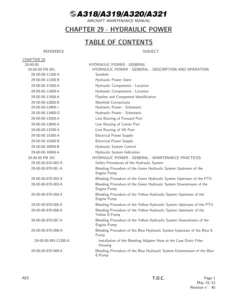
Airbus A318 A319 A320 A321 Servicing Manual Chapter 12 - AES Rev 40 (2012) PDF — PDF page 1 preview
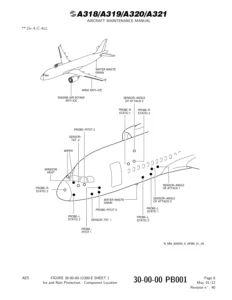
Airbus A318 A319 A320 A321 Servicing Manual Chapter 12 - AES Rev 40 (2012) PDF — PDF page 24 preview
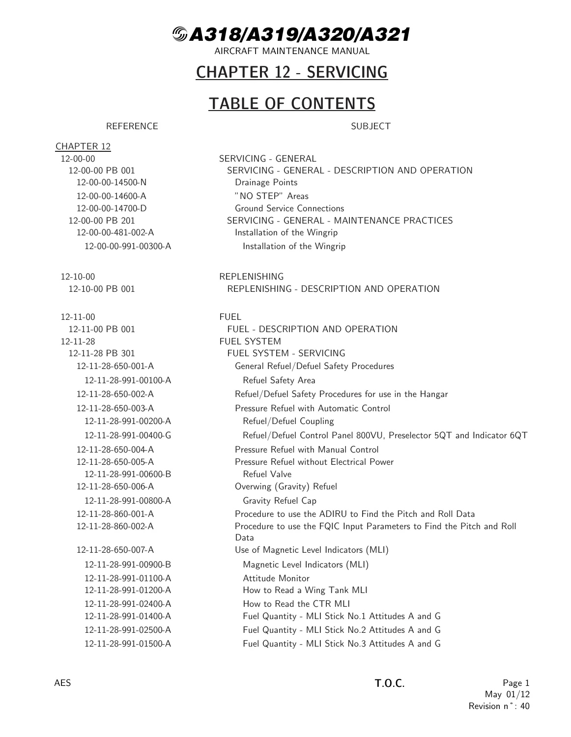
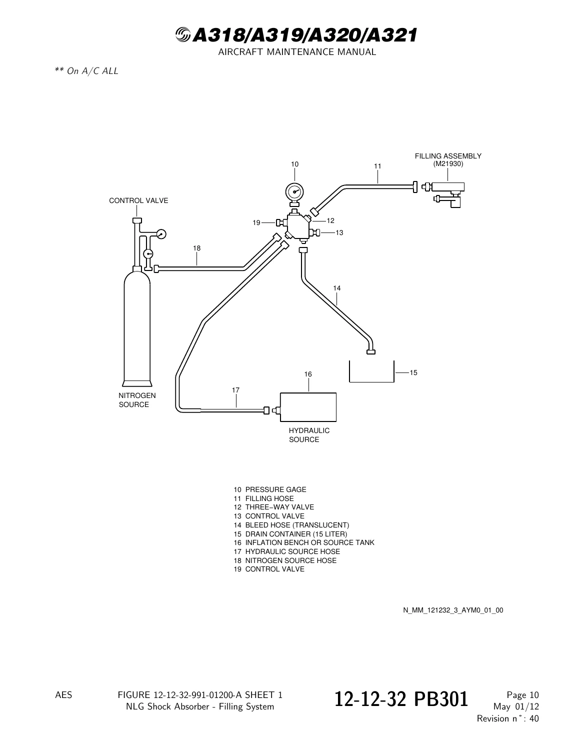
Airbus A318 A319 A320 A321 Servicing Manual Chapter 12 - AES Rev 40 (2012) PDF — PDF page 122 preview

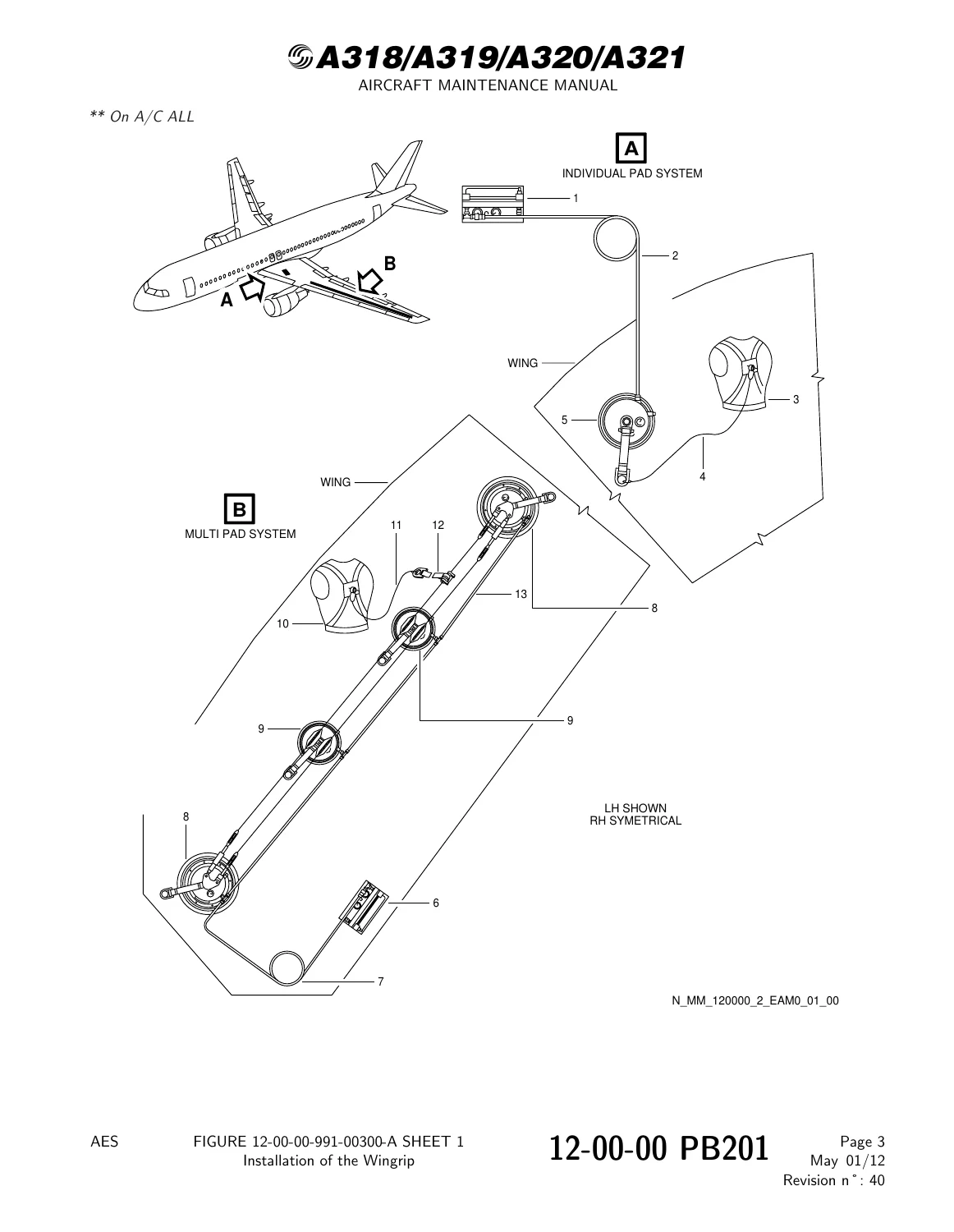
  • Servicing – General (12-00-00): Covers general servicing information including ‘NO STEP’ areas, ground service connections, drainage points, and the installation of the Wingrip safety system for working on the wing.
  • Replenishing (12-10-00): Complete procedures for refueling and defueling, including safety protocols, pressure refueling with automatic and manual control, refueling without electrical power, and gravity/overwing refueling. Also covers the use of Magnetic Level Indicators (MLI) for fuel quantity measurement and attitude monitoring.
  • Hydraulic Fluids (12-12-00): Detailed information on phosphate ester and mineral base fluids, their characteristics, in-service limits, and contamination standards. Includes procedures for filling hydraulic reservoirs with a hand pump or a service cart.
  • Landing Gear Servicing (12-12-32): Thorough coverage of nitrogen filling and oil replenishment for NLG and MLG shock absorbers, as well as maintenance and checks for the alternate brake reservoir, MLG torque link damper, and more.
  • Oil Servicing (12-13-00): Procedures for oil servicing of the IDG (Integrated Drive Generator), THS actuator, flap and slat PCU gearboxes, engine, APU, and starter systems.
  • Gas Servicing (12-14-00): Covers nitrogen filling of hydraulic accumulators, tires, and shock absorbers. Also includes oxygen system servicing and brake accumulator maintenance.
  • Water & Waste Servicing (12-15-00 & 12-16-00): Instructions for filling, draining, and maintaining the potable water and toilet systems.
  • Scheduled Servicing (12-20-00): Defines the frequency and procedures for cleaning, lubrication, and drainage.
  • Cleaning (12-21-00): Detailed guidance for external and internal cleaning of the aircraft, including the cockpit, cargo compartments, galleys, and lavatories. Also covers disinfection, disinsectization, and fumigation procedures.
  • Lubrication (12-22-00): Identifies all lubrication points for flight controls, landing gear, doors, fuselage, and stabilizers, specifying the correct grease and oil types.
  • Unscheduled Servicing (12-30-00): Includes cold weather maintenance procedures, aircraft protection, and pre-conditioning.
  • Sampling for Analysis (12-32-00): Procedures for taking oil, fuel, and hydraulic fluid samples for contamination analysis (IDG, engine, APU, fuel, hydraulic fluid).
  • System Line Flushing (12-36-00): Comprehensive flushing procedures for the Green, Blue, and Yellow hydraulic systems, including engine-driven pumps, PTU, and flight control PCUs.

Complete PDF Bookmark Tree

Complete Bookmarks

The complete bookmarks in the “Airbus A318 A319 A320 A321 Servicing Manual Chapter 12 – AES Rev 40 (2012) PDF” are as follows:

Manual Front Matter
Chapter 05 – TIME LIMITS – MAINTENANCE CHECKS
Chapter 06 – DIMENSIONS AND AREAS
Chapter 07 – LIFTING AND SHORING
Chapter 08 – LEVELING AND WEIGHING
Chapter 09 – TOWING AND TAXIING
Chapter 10 – PARKING, MOORING, STORAGE & RETURN TO SERVICE
Chapter 11 – PLACARDS AND MARKINGS
Chapter 12 – SERVICINGp. 1
Table of Contentsp. 1
12-00 – SERVICING – GENERALp. 15
12-00-00 – SERVICING – GENERALp. 15
12-00-00 PB 001 CONF 00 – SERVICING – GENERAL – DESCRIPTION AND OPERATIONp. 15
Generalp. 15
"NO STEP" Areasp. 16
Ground Service Connectionsp. 17
Drainage Pointsp. 18
Figure 12-00-00-14500-N – Drainage Pointsp. 19
Figure 12-00-00-14600-A – "NO STEP" Areasp. 20
Figure 12-00-00-14700-D – Ground Service Connectionsp. 21
12-00-00 PB 201 CONF 00 – SERVICING – GENERAL – MAINTENANCE PRACTICESp. 22
12-00-00-481-002-A – Installation of the Wingripp. 22
Figure 12-00-00-991-00300-A – Installation of the Wingripp. 24
12-10 – REPLENISHINGp. 25
12-10-00 – REPLENISHINGp. 25
12-10-00 PB 001 CONF 00 – REPLENISHING – DESCRIPTION AND OPERATIONp. 25
Generalp. 25
12-11 – FUELp. 26
12-11-00 – FUELp. 26
12-11-00 PB 001 CONF 00 – FUEL – DESCRIPTION AND OPERATIONp. 26
Generalp. 26
12-11-28 – FUEL SYSTEMp. 27
12-11-28 PB 301 CONF 00 – FUEL SYSTEM – SERVICINGp. 27
12-11-28-650-001-A – General Refuel/Defuel Safety Proceduresp. 27
Figure 12-11-28-991-00100-A – Refuel Safety Areap. 31
12-11-28-650-002-A – Refuel/Defuel Safety Procedures for use in the Hangarp. 32
12-11-28-650-003-A – Pressure Refuel with Automatic Controlp. 33
Figure 12-11-28-991-00200-A – Refuel/Defuel Couplingp. 38
Figure 12-11-28-991-00400-G – Refuel/Defuel Control Panel 800VU, Preselector 5QT and Indicator 6QTp. 39
12-11-28-650-004-A – Pressure Refuel with Manual Controlp. 40
12-11-28-650-005-A – Pressure Refuel without Electrical Powerp. 45
Figure 12-11-28-991-00600-B – Refuel Valvep. 49
12-11-28-650-006-A – Overwing (Gravity) Refuelp. 50
Figure 12-11-28-991-00800-A – Gravity Refuel Capp. 55
12-11-28-860-001-A – Procedure to use the ADIRU to Find the Pitch and Roll Datap. 56
12-11-28-860-002-A – Procedure to use the FQIC Input Parameters to Find the Pitch and Roll Datap. 58
12-11-28-650-007-A – Use of Magnetic Level Indicators (MLI)p. 61
Figure 12-11-28-991-00900-B – Magnetic Level Indicators (MLI)p. 66
Figure 12-11-28-991-01100-A – Attitude Monitorp. 67
Figure 12-11-28-991-01200-A – How to Read a Wing Tank MLIp. 68
Figure 12-11-28-991-02400-A – How to Read the CTR MLIp. 69
Figure 12-11-28-991-01400-A – Fuel Quantity – MLI Stick No.1 Attitudes A and Gp. 70
Figure 12-11-28-991-02500-A – Fuel Quantity – MLI Stick No.2 Attitudes A and Gp. 71
Figure 12-11-28-991-01500-A – Fuel Quantity – MLI Stick No.3 Attitudes A and Gp. 72
Figure 12-11-28-991-02600-A – Fuel Quantity – MLI Stick No.4 Attitudes A and Gp. 73
Figure 12-11-28-991-03600-A – Fuel Quantity – MLI Stick No.5 Attitudes A and Gp. 74
Figure 12-11-28-991-01600-A – Fuel Quantity – MLI Stick No.1 Attitudes B and Fp. 75
Figure 12-11-28-991-02700-A – Fuel Quantity – MLI Stick No.2 Attitudes B and Fp. 76
Figure 12-11-28-991-01700-A – Fuel Quantity – MLI Stick No.3 Attitudes B and Fp. 77
Figure 12-11-28-991-02800-A – Fuel Quantity – MLI Stick No.4 Attitudes B and Fp. 78
Figure 12-11-28-991-03700-A – Fuel Quantity – MLI Stick No.5 Attitudes B and Fp. 79
Figure 12-11-28-991-01800-A – Fuel Quantity – MLI Stick No.1 Attitudes C and Ep. 80
Figure 12-11-28-991-02900-A – Fuel Quantity – MLI Stick No.2 Attitudes C and Ep. 81
Figure 12-11-28-991-01900-A – Fuel Quantity – MLI Stick No.3 Attitudes C and Ep. 82
Figure 12-11-28-991-03000-A – Fuel Quantity – MLI Stick No.4 Attitudes C and Ep. 83
Figure 12-11-28-991-03800-A – Fuel Quantity – MLI Stick No.5 Attitudes C and Ep. 84
Figure 12-11-28-991-02000-A – Fuel Quantity – MLI Stick No.1 Attitude Dp. 85
Figure 12-11-28-991-03100-A – Fuel Quantity – MLI Stick No.2 Attitude Dp. 86
Figure 12-11-28-991-03400-A – Fuel Quantity – MLI Stick No.3 Attitude Dp. 87
Figure 12-11-28-991-03500-A – Fuel Quantity – MLI Stick No.4 Attitude Dp. 88
Figure 12-11-28-991-03900-A – Fuel Quantity – MLI Stick No.5 Attitude Dp. 89
Figure 12-11-28-991-02100-A – Fuel Quantity – CTR MLI Attitudes A and Gp. 90
Figure 12-11-28-991-03200-A – Fuel Quantity – CTR MLI Attitudes B and Fp. 91
Figure 12-11-28-991-02200-A – Fuel Quantity – CTR MLI Attitudes C and Ep. 92
Figure 12-11-28-991-03300-A – Fuel Quantity – CTR MLI Attitude Dp. 93
12-12 – HYDRAULIC FLUIDSp. 94
12-12-00 – HYDRAULIC FLUIDSp. 94
12-12-00 PB 001 CONF 00 – HYDRAULIC FLUIDS – DESCRIPTION AND OPERATIONp. 94
Generalp. 94
Figure 12-12-00-12500-A – Characteristics of Phosphate Ester Base – Hydraulic Fluidsp. 96
Figure 12-12-00-12900-A – Characteristics of Mineral Base Fluidsp. 98
Figure 12-12-00-13200-A – Hydraulic Fluid Property In-Service Limitsp. 99
12-12-29 – HYDRAULIC POWERp. 100
12-12-29 PB 301 CONF 00 – HYDRAULIC POWER – SERVICINGp. 100
12-12-29-611-001-A – Fill the Hydraulic Fluid Reservoir with a Hand Pumpp. 100
Figure 12-12-29-991-00100-A – Ground Service Panel of the Green Hydraulic Systemp. 106
12-12-29-611-002-A – Fill the Hydraulic Fluid Reservoir with a Hydraulic Service Cartp. 107
12-12-32 – LANDING GEARp. 113
12-12-32 PB 301 CONF 00 – LANDING GEAR – SERVICINGp. 113
12-12-32-611-001-A – NLG Shock Absorber Oil Replenishment and Nitrogen Filling (Aircraft on Wheels)p. 113
Figure 12-12-32-991-00100-A – NLG Shock Absorber Replenishment – Location and Detailp. 121
Figure 12-12-32-991-01200-A – NLG Shock Absorber – Filling Systemp. 122
Figure 12-12-32-991-03400-A – NLG Shock Absorber – Dimension Hp. 123
Figure 12-12-32-991-04100-A – NLG Pressure/Extension Data (Weight on Wheels) – Positive Temperaturesp. 124
Figure 12-12-32-991-04200-A – NLG Pressure/Extension Data (Weight on Wheels) – Negative Temperaturesp. 132
12-12-32-611-005-A – NLG Shock Absorber Oil Replenishment and Nitrogen Filling (Aircraft on Jacks)p. 140
Figure 12-12-32-991-04000-A – Pressure/Temperature Table – Shock Absorber Fully Extendedp. 150
12-12-32-611-002-A – Replenishment of the Alternate Brake Reservoirp. 151
Figure 12-12-32-991-00400-A – Alternate-Brake Reservoir Replenishment – Detail and Locationp. 155
12-12-32-611-004-A – Check of MLG Shock Absorber Fluid Levelp. 156
Figure 12-12-32-991-03000-A – MLG Two Stage Shock Absorber Charging Valves – Detail and Locationp. 160
Figure 12-12-32-991-03100-A – MLG Two Stage Shock Absorber – Typical Filling Systemp. 161
Figure 12-12-32-991-03300-A – MLG Two Stage Shock Absorber – Dimension Hp. 162
Figure 12-12-32-991-04300-D – MLG Two-Stage Shock Absorber – Pressure/Extension Graph (Metric Units)p. 163
12-12-32-611-008-A – Hydraulic Replenishment of the MLG Two-Stage Shock Absorberp. 164
Figure 12-12-32-991-00800-A – MLG Two Stage Shock Absorber – Filling Systemp. 172
Figure 12-12-32-991-00900-A – MLG Two Stage Shock Absorber – Replenishment Location and Detailp. 173
12-12-32-611-006-A – Replenishment of the MLG Torque Link Damperp. 174
Figure 12-12-32-991-01400-C – Torque Link Damperp. 178
12-12-32-610-001-A – Check NLG Shock Absorber Fluid Level and Charge Pressure ("Two-Point Check" – Aircraft on Jacks to start)p. 179
Figure 12-12-32-991-02400-A – NLG Maintenance Plan – Aircraft on Jacks to Startp. 187
12-12-32-610-001-A-01 – Check NLG Shock Absorber Fluid Level and Charge Pressure ("Two-Point Check" – Aircraft on Ground to start)p. 188
Figure 12-12-32-991-02500-A – NLG Maintenance Plan – Aircraft on Ground to startp. 196
12-12-32-610-002-A – Check of NLG Shock Absorber Charge Pressure and Fluid Levelp. 197
Figure 12-12-32-991-02600-A – Limit of the H Dimensionp. 206
Figure 12-12-32-991-03800-A – NLG Maintenance Plan – Aircraft in Heavy Configuration to Startp. 207
Figure 12-12-32-991-02800-A – NLG Shock Absorber – Filling Systemp. 208
12-12-32-610-002-A-01 – Check of NLG Shock Absorber Charge Pressure and Fluid Levelp. 209
Figure 12-12-32-991-03900-A – NLG Maintenance Plan – Aircraft in Light Configuration to Startp. 218
12-13 – OILp. 219
12-13-00 – OILp. 219
12-13-00 PB 001 CONF 00 – OIL – DESCRIPTION AND OPERATIONp. 219
Generalp. 219
12-13-24 – ELECTRICAL POWERp. 220
12-13-24 PB 301 CONF 13 – ELECTRICAL POWER – SERVICINGp. 220
12-13-24-680-010-A – Draining of the Oil from the IDGp. 220
Figure 12-13-24-991-15200-B – IDG Servicing – IDG Drain and Fill Portsp. 224
12-13-24-612-011-A – IDG Servicing – Filling of the IDG with Oil or Addition of Oil after a Level Checkp. 225
Figure 12-13-24-991-15000-B – IDG – Servicingp. 230
12-13-24-612-010-A – Do Quick Oil Servicing – Filling of the Integrated Drive Generator (IDG) with Oil for Oil Complement after Level Checkp. 232
Figure 12-13-24-991-15100-A – Quick Oil Servicing – IDGp. 236
12-13-27 – FLIGHT CONTROLSp. 238
12-13-27 PB 301 CONF 00 – FLIGHT CONTROLS – SERVICINGp. 238
12-13-27-612-001-A – Oil Replenishment of the THS Actuatorp. 238
Figure 12-13-27-991-00100-A – THS Actuatorp. 242
12-13-27-612-002-A – Oil Replenishment of the Flap PCU Gearboxp. 243
Figure 12-13-27-991-00200-A – Flap Power-Control Unit (6201CM)p. 246
12-13-27-612-003-A – Oil Replenishment of the Slat PCU Gearboxp. 247
Figure 12-13-27-991-00300-A – Slat Power-Control Unit (6001CM)p. 250
12-13-27-612-004-A – Drain and Refill Offset Gearboxes of Rotary Actuators with Semi-fluidp. 251
Figure 12-13-27-991-00400-A – Flap Actuators – Tracks 1, 2, 3 and 4p. 261
12-13-27-612-005-A – Drain and Refill Flap Actuator Assemblies with Semi-fluidp. 265
Figure 12-13-27-991-00500-A – Flap Actuator – Track 1p. 273
Figure 12-13-27-991-00600-A – Flap Actuators – Tracks 2 thru 4p. 274
12-13-29 – HYDRAULIC POWERp. 277
12-13-29 PB 301 CONF 00 – HYDRAULIC POWER – SERVICINGp. 277
12-13-29-600-001-A – Servicing of the Ram Air Turbine (RAT)p. 277
Figure 12-13-29-991-00100-A – Ram Air Turbinep. 280
12-13-49 – APUp. 281
12-13-49 PB 301 CONF 00 – APU – SERVICINGp. 281
12-13-49-612-001-A – Check APU Oil Level and Replenishp. 281
12-13-79 – ENGINE OILp. 282
12-13-79 PB 301 CONF 13 – ENGINE OIL – SERVICINGp. 282
12-13-79-610-010-A – Drain the Engine Oil Systemp. 282
Figure 12-13-79-991-15000-A – Oil Tank Filler Capp. 286
Figure 12-13-79-991-15100-A – Oil Tank and Oil Pressure Pump Filter Drainsp. 287
Figure 12-13-79-991-15200-A – External Gearbox Chip Detectorsp. 288
Figure 12-13-79-991-15300-A – Oil Scavenge Filter Drainp. 289
12-13-79-610-011-A – Check Oil Level and Replenishp. 290
Figure 12-13-79-991-15400-A – Illustration of the Sight Glass Markingsp. 293
12-13-79-610-012-A – Prime the Engine Oil Systemp. 294
12-13-80 – ENGINE STARTINGp. 295
12-13-80 PB 301 CONF 13 – ENGINE STARTING – SERVICINGp. 295
12-13-80-600-011-B – Drain and Replenish Oil Systemp. 295
Figure 12-13-80-991-15100-C – Starter Drain Plug and magnetic Chip Detectorp. 299
12-13-80-600-010-B – Replenishment of Starter Oil Systemp. 300
Figure 12-13-80-991-15300-A – Starter – Oil Servicingp. 303
12-14 – GASp. 304
12-14-00 – GASp. 304
12-14-00 PB 001 CONF 00 – GAS – DESCRIPTION AND OPERATIONp. 304
Generalp. 304
12-14-29 – HYDRAULIC POWERp. 305
12-14-29 PB 301 CONF 00 – HYDRAULIC POWER – SERVICINGp. 305
12-14-29-614-001-A – Fill the Hydraulic Power Accumulators with Nitrogenp. 305
Figure 12-14-29-991-00100-B – Hydraulic Power Accumulators – Locationp. 309
Figure 12-14-29-991-00300-A – Hydraulic Power Accumulator – Pressure Graphp. 311
12-14-32 – LANDING GEARp. 312
12-14-32 PB 301 CONF 00 – LANDING GEAR – SERVICINGp. 312
12-14-32-614-001-A – Nitrogen Filling of the Tiresp. 312
12-14-32-614-002-A – Nitrogen Filling of the Yellow Hydraulic System, Brake Pressure Accumulatorp. 315
Figure 12-14-32-991-00100-A – Brake Accumulator – Filling System Schematicp. 319
Figure 12-14-32-991-00200-A – Brake Accumulator Assembly – Detail and Locationp. 320
Figure 12-14-32-991-00300-B – Yellow System Brake Accumulator – Pressure Graphp. 321
12-14-32-614-003-A – Check of MLG Shock Absorber Charge Pressurep. 322
Figure 12-14-32-991-01900-A – Possible Points of Leakage from the Gland Sealsp. 333
Figure 12-14-32-991-02000-B – Details of the Spare-Seal Activating-Valvep. 334
Figure 12-14-32-991-00400-A – MLG Two Stage Shock Absorber Charging Valves – Detail and Locationp. 335
Figure 12-14-32-991-02100-B – MLG Two Stage Shock Absorber – Typical Filling Systemp. 336
Figure 12-14-32-991-00500-D – MLG Two-Stage Shock Absorber – Pressure/Extension Graph (Metric Units)p. 337
Figure 12-14-32-991-02500-D – MLG Two Stage Shock Absorber – Pressure Extension Graph (Imp. Units)p. 340
Figure 12-14-32-991-02700-H – Charging Pressures – Weight off Wheelsp. 343
12-14-32-200-001-A – Inspection of the MLG Shock Absorbers Before Flightp. 345
Figure 12-14-32-991-02400-A – MLG Two-Stage Shock Absorber – Dimension Hp. 347
12-14-32-614-004-A – Check NLG Shock Absorber Charge Pressurep. 348
Figure 12-14-32-991-00600-A – NLG Charging Valve – Detail and Locationp. 356
Figure 12-14-32-991-01700-A – NLG Shock Absorber – Filling Systemp. 357
Figure 12-14-32-991-03000-A – Pressure/Temperature Table – Shock Absorber Fully Extendedp. 358
Figure 12-14-32-991-03100-A – NLG Shock Absorber – Dimension Hp. 359
Figure 12-14-32-991-03200-A – NLG Pressure/Extension Data (Weight on Wheels) – Positive Temperaturesp. 360
Figure 12-14-32-991-03300-A – NLG Pressure/Extension Data (Weight on Wheels) – Negative Temperaturesp. 368
12-14-32-200-002-A – Check NLG Shock Absorber Bottomingp. 376
12-14-35 – OXYGENp. 378
12-14-35 PB 301 CONF 00 – OXYGEN – SERVICINGp. 378
12-14-35-600-001-A – Servicing of the Oxygen-Replenishingp. 378
Figure 12-14-35-991-00100-A – Location of the Oxygen Systemp. 382
Figure 12-14-35-991-00300-A – Filling Pressurep. 383
Figure 12-14-35-991-00200-A – Location of the Oxygen Fill Port.p. 384
12-15 – WATERp. 385
12-15-00 – WATERp. 385
12-15-00 PB 001 CONF 00 – WATER – DESCRIPTION AND OPERATIONp. 385
Generalp. 385
Descriptionp. 386
12-15-38 – POTABLE WATERp. 387
12-15-38 PB 301 CONF 00 – POTABLE WATER – SERVICINGp. 387
12-15-38-613-001-A – Fill the Potable Water Tank System (Aircraft Electrical Power Available)p. 387
Figure 12-15-38-991-00100-D – Potable Water Service-Panel 2023VUp. 391
12-15-38-613-002-A – Fill the Potable Water Tank System (Aircraft Electrical Power not Available)p. 392
Figure 12-15-38-991-00200-B – Potable water Service-Panel 2023VUp. 394
12-16 – LAVATORYp. 395
12-16-00 – LAVATORYp. 395
12-16-00 PB 001 CONF 00 – LAVATORY – DESCRIPTION AND OPERATIONp. 395
Generalp. 395
Descriptionp. 396
12-16-25 – LAVATORY ARTICLEp. 397
12-16-25 PB 301 CONF 00 – LAVATORY ARTICLE – SERVICINGp. 397
12-16-25-613-001-A – Servicing of the Liquid Soap Dispenserp. 397
Figure 12-16-25-991-00100-C – Soap Dispenserp. 399
12-16-38 – TOILET SANITARY FLUIDp. 400
12-16-38 PB 301 CONF 00 – TOILET SANITARY FLUID – SERVICINGp. 400
12-16-38-613-001-A – Servicing of the Toilet Systemp. 400
Figure 12-16-38-991-00100-I – Service Panel – Locationp. 403
12-17 – RAIN REPELLENTp. 404
12-17-00 – RAIN REPELLENTp. 404
12-17-00 PB 001 CONF 00 – RAIN REPELLENT – DESCRIPTION AND OPERATIONp. 404
Generalp. 404
12-17-30 – ICE AND RAIN PROTECTIONp. 405
12-17-30 PB 301 CONF 00 – ICE AND RAIN PROTECTION – SERVICINGp. 405
12-17-30-200-001-A – Inspection/Check of the Level and Pressure of the Rain Repellent Fluidp. 405
Figure 12-17-30-991-00100-C – Rain-Repellent Fluid Gagep. 406
12-20 – SCHEDULED SERVICINGp. 407
12-20-00 – SCHEDULED SERVICINGp. 407
12-20-00 PB 001 CONF 00 – SCHEDULED SERVICING – DESCRIPTION AND OPERATIONp. 407
Generalp. 407
12-21 – CLEANINGp. 408
12-21-00 – CLEANINGp. 408
12-21-00 PB 001 CONF 00 – CLEANING – DESCRIPTION AND OPERATIONp. 408
Generalp. 408
12-21-11 – EXTERNAL CLEANINGp. 409
12-21-11 PB 301 CONF 00 – EXTERNAL CLEANING – SERVICINGp. 409
12-21-11-615-002-A – External Cleaningp. 409
Figure 12-21-11-991-00200-A – AOA Protectionp. 420
Figure 12-21-11-991-00300-A – Gun Direction and Spray Shapep. 421
Figure 12-21-11-991-00400-A – Cleaning Methodsp. 422
Figure 12-21-11-991-00600-A – Specific Composite Partsp. 423
Figure 12-21-11-991-00500-A – FWD Section Sensitive Parts (Typical)p. 425
12-21-12 – INTERNAL CLEANINGp. 426
12-21-12 PB 301 CONF 00 – INTERNAL CLEANING – SERVICINGp. 426
12-21-12-100-001-A – Cleaning of the Cockpit Display-Unitsp. 426
Figure 12-21-12-991-00400-A – Cockpit Display Unitsp. 427
12-21-12-100-002-A – Cleaning of the Cockpit Equipment/Furnishingsp. 428
Figure 12-21-12-991-00700-A – Linings and Furnishings – Cockpitp. 431
Figure 12-21-12-991-00100-A – Vacuum Cleaner Socketsp. 432
12-21-12-100-003-A – Cleaning of the Carpets and Non-Textile Floor Covering (NTF)p. 433
Figure 12-21-12-991-00500-A – Component Location/Surface Finish Identificationp. 435
12-21-12-100-004-A – Cleaning of the Plastic Surfaces and Mirrorsp. 437
Figure 12-21-12-991-00600-A – Linings and Furnishings – Lavatoryp. 440
12-21-12-100-005-A – Cleaning of the Seat Covers and the Curtainsp. 441
12-21-12-100-006-A – Cleaning of the Light Alloy and Steel Componentsp. 443
12-21-12-100-007-A – Cleaning of the Cargo Compartmentsp. 445
12-21-12-100-008-A – Cleaning of the Cabin Monitors and Display Screens (if installed)p. 447
12-21-12-100-009-A – Cleaning of the Plastic Wash Basin in the Lavatoriesp. 448
12-21-12-100-010-A – Cleaning of the Galleysp. 451
12-21-12-670-001-A – Disinfection of the Aircraft Equipment and Furnishingp. 454
12-21-12-670-002-A – Disinsectization of the Aircraft Equipment and Furnishingp. 458
12-21-12-670-004-A – Fumigation of the Fuselage Pressurized Areas with Carbon-Dioxide (CO2 Gas)p. 463
Figure 12-21-12-991-00200-A – Adapter Air-Outflow Valvep. 470
Figure 12-21-12-991-00800-A – Adapter Cockpit Sliding Windowp. 471
12-21-12-670-006-A – Special Precautions to Apply Insecticide Agent in Auxiliary Area Compartments and Cargo Compartments, during Turn-Aroundp. 472
12-21-13 – DUST REMOVALp. 474
12-21-13 PB 701 CONF 00 – DUST REMOVAL – CLEANING/PAINTINGp. 474
12-21-13-100-001-A – Cleaning of the Avionics Compartment and the Cockpitp. 474
Figure 12-21-13-991-00100-A – Location of Units in the Cockpit (Panels 10VU and 13VU)p. 491
Figure 12-21-13-991-00200-A – Location of Shelves and Computers in the Avionics Compartmentp. 492
12-21-13-100-002-A – Cleaning of the Grids of the 70VU, 103VU, 106VU and 107VUp. 493
Figure 12-21-13-991-00300-A – Location of Units in Avionics Compartmentp. 495
12-22 – LUBRICATIONp. 496
12-22-00 – LUBRICATIONp. 496
12-22-00 PB 001 CONF 00 – LUBRICATION – DESCRIPTION AND OPERATIONp. 496
Generalp. 496
Figure 12-22-00-12400-A – Lubrication Symbolsp. 498
12-22-27 – FLIGHT CONTROLSp. 499
12-22-27 PB 301 CONF 00 – FLIGHT CONTROLS – SERVICINGp. 499
12-22-27-640-003-A – Lubrication of Trimmable Horizontal Stabilizer Actuator Ball Screw Nutp. 499
Figure 12-22-27-991-00300-A – Trimmable Horizontal Stabilizer (THS) Actuator.p. 504
12-22-27-640-004-A – Lubricate all Carriage Rollers on all Flap Tracksp. 505
Figure 12-22-27-991-00100-C – Flap Track Carriage Rollers – Lubrication Pointsp. 510
Figure 12-22-27-991-00600-A – Flap Track Carriage Rollers and Drive Lever Arm – Lubrication Pointsp. 511
12-22-27-640-005-A – Lubrication of Spoiler No.1 to 5 Servo Control Bearingsp. 513
Figure 12-22-27-991-00700-A – Spoiler Servo Control Bearing – Lubrication Pointp. 516
12-22-27-640-006-A – Lubrication of all Slat Track Rollers, Pinion Bearings, Pinions and Rack Teethp. 517
Figure 12-22-27-991-00200-A – Slats – Lubrication Pointsp. 521
12-22-27-640-007-A – Lubrication of the THS Mechanical Control Chainsp. 522
Figure 12-22-27-991-00400-A – Removal/Installation of the Protective Coversp. 525
Figure 12-22-27-991-00500-A – Control Chainsp. 526
12-22-27-640-008-A – Remove Flap Rotary Actuators For Regreasingp. 528
12-22-27-640-009-A – Lubrication of the THS Rear Cable (Area of Tension Regulator)p. 532
Figure 12-22-27-991-00800-A – Removal/Installation of the Protective Covers.p. 535
12-22-29 – HYDRAULIC POWERp. 536
12-22-29 PB 301 CONF 00 – HYDRAULIC POWER – SERVICINGp. 536
12-22-29-600-001-A – Lubrication of the Ram Air Turbine (RAT) Door Hingesp. 536
Figure 12-22-29-991-00100-A – Lubrication of the Ram Air Turbine (RAT) Door Hingesp. 538
12-22-32 – LANDING GEARp. 539
12-22-32 PB 301 CONF 00 – LANDING GEAR – SERVICINGp. 539
12-22-32-640-001-A – Lubrication of Main Landing Gear and Doorsp. 539
Figure 12-22-32-991-00100-H – MLG – Lubrication Pointsp. 544
Figure 12-22-32-991-00200-D – MLG Door and Uplocks – Lubrication Pointsp. 552
12-22-32-640-002-A – Lubrication of Nose Landing Gear and Doorsp. 553
Figure 12-22-32-991-00300-C – NLG – Lubrication Pointsp. 558
Figure 12-22-32-991-00400-A – NLG Door and Uplocks – Lubrication Pointsp. 566
Figure 12-22-32-991-00300-A – DELETEDp. 567
12-22-52 – DOORSp. 568
12-22-52 PB 301 CONF 00 – DOORS – SERVICINGp. 568
12-22-52-640-002-A – Lubrication of the FWD and AFT Cargo-Compartment Doorsp. 568
Figure 12-22-52-991-00200-D – Lubrication of the Switch Mechanism and the Piano Hinges at the FWD Cargo-Compartment Doorp. 572
Figure 12-22-52-991-00300-F – Lubrication of the Switch Mechanism and the Piano Hinges of the AFT Cargo-Compartment Doorp. 573
Figure 12-22-52-991-03200-A – Lubrication of the Vent Door Mechanismp. 574
Figure 12-22-52-991-03000-B – Lubrication of the Latching Unitp. 575
Figure 12-22-52-991-03100-A – Lubrication of the Interlock Mechanismp. 576
Figure 12-22-52-991-03300-G – Lubrication of the Drift Pin Mechanismp. 577
12-22-52-640-005-A – Lubrication of the Door-Warning Proximity-Switch Actuating-Mechanismp. 578
Figure 12-22-52-991-00700-A – Actuating Mechanism of Proximity Switchesp. 580
12-22-52-640-006-A – Lubrication of the External Control Handles of the FWD and AFT Passenger/Crew Doorsp. 581
Figure 12-22-52-991-00800-A – Lubrication of the External Control Handles-FWD and AFT Passenger/Crew Doorsp. 584
Figure 12-22-52-991-00600-B – Lubrication of the Telescopic Armp. 585
12-22-52-640-007-A – Lubrication of the BULK-Cargo Compartment-Door Handle and Hinge Arms Bearingsp. 586
Figure 12-22-52-991-01500-A – External Door Handle of Bulk Cargo-Compartment Doorp. 588
Figure 12-22-52-991-03700-A – Lubrication of the Hinge Arms Bearingsp. 589
12-22-52-640-008-A – Lubrication of the Avionics Compartment-Door Handlesp. 590
Figure 12-22-52-991-01000-A – External Door Handle of Avionics Compartment Doorsp. 592
12-22-52-640-009-A – Lubrication of the FWD and AFT Cargo-Compartment Door Handlep. 593
Figure 12-22-52-991-01400-B – Lubrication of the FWD and AFT Cargo Compartment-Door Handlep. 596
12-22-52-640-014-A – Lubrication of Safety Pin Guide Fitting and Door Arming/Disarming Mechanismp. 598
Figure 12-22-52-991-02200-B – Lubrication of the Safety Guide Fitting and Door Arming/Disarming Mechanismp. 601
Figure 12-22-52-991-02900-A – Lubrication of the Girt Bar Springp. 602
12-22-52-640-016-A – Lubrication of the Hinge-Arm Support-Fitting Bearingsp. 603
Figure 12-22-52-991-02800-A – Lubrication of the Hinge-Arm Support-Fitting Bearingsp. 605
12-22-53 – FUSELAGEp. 606
12-22-53 PB 301 CONF 00 – FUSELAGE – SERVICINGp. 606
12-22-53-640-001-A – Lubrication of Trimmable Horizontal Stabilizer Bearings and Attachment Fittings with Grease Mat. No. 04-004p. 606
Figure 12-22-53-991-00100-A – Lubrication Points of the Hinge and Attach Fittings of the Horizontal Stabilizerp. 608
12-22-53-640-002-A – Lubrication of Trimmable Horizontal Stabilizer Bearings and Attachment Fittings with Grease Mat. No. 04-037p. 609
Figure 12-22-53-991-00200-A – Lubrication of the Attach and Hinge fittings of the Horizontal Stabilizerp. 611
12-22-55 – STABILIZERSp. 612
12-22-55 PB 301 CONF 00 – STABILIZERS – SERVICINGp. 612
12-22-55-640-001-A – Lubrication of Rudder Hinge Bearing No. 6 with Grease Mat. No. 04-004p. 612
Figure 12-22-55-991-00100-A – Rudder Hinge Bearing No. 6p. 615
12-22-55-640-002-A – Lubrication of Rudder Hinge Bearing No. 6 with Grease MAT. No. 04-037p. 616
Figure 12-22-55-991-00200-A – Rudder Hinge Bearing No. 6p. 619
12-22-56 – WINDOWSp. 620
12-22-56 PB 301 CONF 00 – WINDOWS – SERVICINGp. 620
12-22-56-600-001-A – Lubrication of the Cockpit Sliding Window Tracksp. 620
Figure 12-22-56-991-00100-A – Lubrication of Sliding Windows Mechanism Tracksp. 622
12-24 – DRAINAGEp. 623
12-24-00 – DRAINAGEp. 623
12-24-00 PB 001 CONF 00 – DRAINAGE – DESCRIPTION AND OPERATIONp. 623
Generalp. 623
12-24-34 – AIR DATA SYSTEMp. 624
12-24-34 PB 301 CONF 00 – AIR DATA SYSTEM – SERVICINGp. 624
12-24-34-600-001-A – Bleeding of the Standby Air Data Systemp. 624
Figure 12-24-34-991-00100-A – Standby Air Data System Water Drainp. 626
12-24-38 – POTABLE WATER SYSTEMp. 627
12-24-38 PB 201 CONF 00 – POTABLE WATER SYSTEM – MAINTENANCE PRACTICESp. 627
12-24-38-680-001-A – Draining of the Potable Water System (with Electrical Power)p. 627
Figure 12-24-38-991-00400-C – Potable Water Service-Panelp. 630
12-24-38-680-002-A – Draining of the Potable Water System (without Electrical Power)p. 631
12-28 – USE OF MANUAL (MAGNETIC) FUEL QUANTITY INDICATORSp. 634
12-28-00 – USE OF MANUAL (MAGNETIC) FUEL QUANTITY INDICATORSp. 634
12-28-00 PB 001 CONF 00 – USE OF MANUAL (MAGNETIC) FUEL QUANTITY INDICATORS – DESCRIPTION AND OPERATIONp. 634
Generalp. 634
12-30 – UNSCHEDULED SERVICINGp. 635
12-30-00 – UNSCHEDULED SERVICINGp. 635
12-30-00 PB 001 CONF 00 – UNSCHEDULED SERVICING – DESCRIPTION AND OPERATIONp. 635
Generalp. 635
12-31 – AIRCRAFT PROTECTIONp. 636
12-31-00 – AIRCRAFT PROTECTIONp. 636
12-31-00 PB 001 CONF 00 – AIRCRAFT PROTECTION – DESCRIPTION AND OPERATIONp. 636
Generalp. 636
12-31-00 PB 201 CONF 00 – AIRCRAFT PROTECTION – MAINTENANCE PRACTICESp. 637
12-31-00-600-001-A – Cold Weather Maintenance Proceduresp. 637
12-31-11 – ANTI-ICING PROTECTIONp. 643
12-31-11 PB 201 CONF 00 – ANTI-ICING PROTECTION – MAINTENANCE PRACTICESp. 643
12-31-11-660-001-A – Cold Weather Maintenance – Anti-Icing Protectionp. 643
12-31-12 – ICE AND SNOW REMOVALp. 648
12-31-12 PB 201 CONF 00 – ICE AND SNOW REMOVAL – MAINTENANCE PRACTICESp. 648
12-31-12-660-002-A – De-icing of the Aircraft in Power-Off Conditionp. 648
12-31-12-660-003-A – De-icing of the Aircraft in Power-On Conditionp. 655
12-31-12-660-006-A – De-icing of the Aircraft by InfraRed Facilitiesp. 661
12-31-12-660-008-A – Forward Fuselage Ice Accretion De-icingp. 662
12-31-12-660-007-A – De-icing of the Aircraft after Landing with Snow on the Runwayp. 666
12-31-21 – COLD WEATHER MAINTENANCE – AIR CONDITIONINGp. 669
12-31-21 PB 201 CONF 00 – COLD WEATHER MAINTENANCE – AIR CONDITIONING – MAINTENANCE PRACTICESp. 669
12-31-21-660-001-A – Cold Weather Maintenance – Air Conditioningp. 669
12-31-24 – COLD WEATHER MAINTENANCE – ELECTRICAL POWERp. 671
12-31-24 PB 201 CONF 00 – COLD WEATHER MAINTENANCE – ELECTRICAL POWER – MAINTENANCE PRACTICESp. 671
12-31-24-660-001-A – Cold Weather Maintenance – Electrical Powerp. 671
Figure 12-31-24-991-00100-A – Batteries Cooling Down Curvep. 672
12-31-25 – COLD WEATHER MAINTENANCE – EQUIPMENT/FURNISHINGSp. 673
12-31-25 PB 201 CONF 00 – COLD WEATHER MAINTENANCE – EQUIPMENT/FURNISHINGS – MAINTENANCE PRACTICESp. 673
12-31-25-660-001-A – Cold Weather Maintenance – Equipment/Furnishingsp. 673
12-31-27 – COLD WEATHER MAINTENANCE – FLIGHT CONTROLSp. 677
12-31-27 PB 201 CONF 00 – COLD WEATHER MAINTENANCE – FLIGHT CONTROLS – MAINTENANCE PRACTICESp. 677
12-31-27-660-001-A – Cold Weather Maintenance – Flight Controlsp. 677
12-31-28 – COLD WEATHER MAINTENANCE – FUELp. 679
12-31-28 PB 201 CONF 00 – COLD WEATHER MAINTENANCE – FUEL – MAINTENANCE PRACTICESp. 679
12-31-28-660-001-A – Cold Weather Maintenance – Fuelp. 679
12-31-31 – COLD WEATHER MAINTENANCE – INDICATING/RECORDING SYSTEMS AND NAVIGATIONp. 682
12-31-31 PB 201 CONF 00 – COLD WEATHER MAINTENANCE – INDICATING/RECORDING SYSTEMS AND NAVIGATION – MAINTENANCE PRACTICESp. 682
12-31-31-660-001-A – Cold Weather Maintenance – Indicating/Recording systems and Navigationp. 682
12-31-32 – COLD WEATHER MAINTENANCE – LANDING GEARp. 684
12-31-32 PB 201 CONF 00 – COLD WEATHER MAINTENANCE – LANDING GEAR – MAINTENANCE PRACTICESp. 684
12-31-32-660-001-A – Cold Weather Maintenance – Landing Gearp. 684
12-31-35 – COLD WEATHER MAINTENANCE – OXYGENp. 686
12-31-35 PB 201 CONF 00 – COLD WEATHER MAINTENANCE – OXYGEN – MAINTENANCE PRACTICESp. 686
12-31-35-660-001-A – Cold Weather Maintenance – Oxygen Systemp. 686
12-31-38 – COLD WEATHER MAINTENANCE – WATER/ WASTEp. 688
12-31-38 PB 201 CONF 00 – COLD WEATHER MAINTENANCE – WATER/ WASTE – MAINTENANCE PRACTICESp. 688
12-31-38-660-001-A – Cold Weather Maintenance – Water/Wastep. 688
12-31-49 – COLD WEATHER MAINTENANCE – AIRBORNE AUXILIARY POWERp. 692
12-31-49 PB 201 CONF 00 – COLD WEATHER MAINTENANCE – AIRBORNE AUXILIARY POWER – MAINTENANCE PRACTICESp. 692
12-31-49-660-001-A – Cold Weather Maintenance – Auxiliary Power Unitp. 692
12-31-51 – COLD WEATHER MAINTENANCE – STRUCTUREp. 696
12-31-51 PB 201 CONF 00 – COLD WEATHER MAINTENANCE – STRUCTURE – MAINTENANCE PRACTICESp. 696
12-31-51-660-001-A – Cold Weather Maintenance – Structurep. 696
12-31-52 – COLD WEATHER MAINTENANCE – DOORSp. 698
12-31-52 PB 201 CONF 00 – COLD WEATHER MAINTENANCE – DOORS – MAINTENANCE PRACTICESp. 698
12-31-52-660-001-A – Cold Weather Maintenance – Doorsp. 698
12-31-71 – COLD WEATHER MAINTENANCE – POWER PLANTp. 707
12-31-71 PB 201 CONF 00 – COLD WEATHER MAINTENANCE – POWER PLANT – MAINTENANCE PRACTICESp. 707
12-31-71-660-001-A – Cold Weather Maintenance – Power Plantp. 707
12-32 – SAMPLING FOR ANALYSISp. 710
12-32-00 – SAMPLING FOR ANALYSISp. 710
12-32-00 PB 001 CONF 00 – SAMPLING FOR ANALYSIS – DESCRIPTION AND OPERATIONp. 710
Generalp. 710
12-32-24 – INTEGRATED DRIVE GENERATOR OILp. 711
12-32-24 PB 301 CONF 00 – INTEGRATED DRIVE GENERATOR OIL – SERVICINGp. 711
12-32-24-281-001-A – Sampling of the IDG Oil for Analysisp. 711
Figure 12-32-24-991-00100-C – IDG Oil Sampling for Analysisp. 715
12-32-28 – FUELp. 716
12-32-28 PB 301 CONF 00 – FUEL – SERVICINGp. 716
12-32-28-281-001-A – Drain Water Contentp. 716
Figure 12-32-28-991-00100-B – Fuel Sampling For Analysisp. 721
Figure 12-32-28-991-00700-B – Fuel Sampling For Analysis – Suction Procedurep. 722
12-32-28-281-003-A – Sample Fuel for Microbiological Contamination Analysisp. 723
Figure 12-32-28-991-00500-A – Maintenance Plan Flowchart – Microbiological Contaminationp. 732
Figure 12-32-28-991-00600-A – Microbiological Contamination Test Kits – Comparison Tablep. 733
12-32-29 – HYDRAULIC FLUIDp. 735
12-32-29 PB 301 CONF 00 – HYDRAULIC FLUID – SERVICINGp. 735
12-32-29-281-001-A – Hydraulic Fluid Sample of Green, Blue and Yellow Systems for Analysisp. 735
Figure 12-32-29-991-00100-A – Sampling Valves – Location and Operationp. 744
12-32-49 – APUp. 746
12-32-49 PB 301 CONF 00 – APU – SERVICINGp. 746
12-32-49-281-001-A – Oil Sampling for Analysisp. 746
Figure 12-32-49-991-00100-B – Oil Sampling for Analysisp. 750
12-32-79 – ENGINE OILp. 751
12-32-79 PB 301 CONF 13 – ENGINE OIL – SERVICINGp. 751
12-32-79-600-010-A – Sampling of the Engine Oil for Analysisp. 751
Figure 12-32-79-991-15000-A – Oil Tank Filler Capp. 754
12-33 – PRE-CONDITIONINGp. 755
12-33-00 – PRE-CONDITIONINGp. 755
12-33-00 PB 001 CONF 00 – PRE-CONDITIONING – DESCRIPTION AND OPERATIONp. 755
Generalp. 755
12-33-21 – GROUND AIR PRE-CONDITIONINGp. 756
12-33-21 PB 201 CONF 00 – GROUND AIR PRE-CONDITIONING – MAINTENANCE PRACTICESp. 756
12-33-21-618-001-A – Pre-conditioning through the LP Ground Connectionp. 756
Figure 12-33-21-991-00300-A – LP and HP Ground Connectorsp. 759
12-33-21-618-001-A-01 – Pre-conditioning through the HP Ground Connectionp. 760
Figure 12-33-21-991-00100-A – Air Condition Panelp. 764
12-33-21-618-001-A-02 – Pre-conditioning with the APUp. 765
12-33-21 PB 301 CONF 00 – GROUND AIR PRE-CONDITIONING – SERVICINGp. 769
12-33-21-600-001-A – Pre-conditioning through the LP Ground Connectionp. 769
12-34 – GROUNDING POINTSp. 771
12-34-00 – GROUNDING POINTSp. 771
12-34-00 PB 001 CONF 00 – GROUNDING POINTS – DESCRIPTION AND OPERATIONp. 771
Generalp. 771
12-34-24 – AIRCRAFT GROUNDINGp. 772
12-34-24 PB 201 CONF 00 – AIRCRAFT GROUNDING – MAINTENANCE PRACTICESp. 772
12-34-24-869-001-B – Aircraft Grounding for the Refuel/Defuel and Oxygen Servicing Operationsp. 772
Figure 12-34-24-991-00100-A – Location of the Grounding Point on the Nose Landing Gearp. 774
Figure 12-34-24-991-00200-A – Location of the Grounding Point on the Main Landing Gearp. 775
Figure 12-34-24-991-00300-A – Grounding Point on the Wing Upper Surfacep. 776
12-34-24-869-002-A – Aircraft Grounding for the Maintenance Operationsp. 777
12-36 – SYSTEM LINE FLUSHINGp. 779
12-36-00 – SYSTEM LINE FLUSHINGp. 779
12-36-00 PB 001 CONF 00 – SYSTEM LINE FLUSHING – DESCRIPTION AND OPERATIONp. 779
Generalp. 779
12-36-29 – HYDRAULIC POWERp. 780
12-36-29 PB 301 CONF 00 – HYDRAULIC POWER – SERVICINGp. 780
12-36-29-170-001-A – Flushing of the Green Hydraulic System of the Engine Driven Pump (EDP)p. 780
Figure 12-36-29-991-00100-A – Green Hydraulic System of the EDP 1030GK – Flushing Schematicp. 785
12-36-29-170-002-A – Flushing of the Yellow Hydraulic System of the Engine Driven Pump (EDP)p. 786
Figure 12-36-29-991-00200-A – Yellow Hydraulic System of the EDP 3030GD – Flushing Schematicp. 791
12-36-29-170-003-A – Flushing of the Blue Hydraulic System of the Electrically Driven Pumpp. 792
Figure 12-36-29-991-00300-A – Blue Hydraulic System of the Electrically Driven Pump 2075GJ – Flushing Schematicp. 796
12-36-29-170-004-A – Flushing of the Green Hydraulic System of the Power Transfer Unit (PTU)p. 797
Figure 12-36-29-991-00400-A – Green Hydraulic System of the PTU 1088GM – Flushing Schematicp. 800
12-36-29-170-005-A – Flushing of the Yellow Hydraulic System of the Power Transfer Unit (PTU)p. 801
Figure 12-36-29-991-00500-A – Yellow Hydraulic System of the PTU 1088GM – Flushing Schematicp. 804
12-36-29-170-006-A – Flushing of the Yellow Hydraulic System of the Electrically Driven Pumpp. 805
Figure 12-36-29-991-00600-A – Yellow Hydraulic System of the Electrically Driven Pump 3075GX – Flushing Schematicp. 809
12-36-29-170-007-A – Flushing of the Green Hydraulic System of the Flap Power Control-Unit (PCU) 6201CMp. 810
Figure 12-36-29-991-00700-A – Green Hydraulic System of the Flap PCU 6201CM – Flushing Schematicp. 814
12-36-29-170-008-A – Flushing of the Yellow Hydraulic System of the Flap Power Control-Unit (PCU) (PCU) 6201CMp. 815
Figure 12-36-29-991-00800-A – Yellow Hydraulic System of the Flap PCU 6201CM – Flushing Schematicp. 819
12-36-29-170-009-A – Flushing of the Green Hydraulic System of the Slat Power Control-Unit (PCU) 6001CMp. 820
Figure 12-36-29-991-00900-A – Green Hydraulic System of the Slat PCU 6001CM – Flushing Schematicp. 824
12-36-29-170-010-A – Flushing of the Blue Hydraulic System of the Slat Power Control-Unit (PCU) 6001CM.p. 825
Figure 12-36-29-991-01000-A – Blue Hydraulic System of the Slat PCU 6001CM – Flushing Schematicp. 829
12-36-29-170-011-A – Flushing of the Blue Hydraulic System of the Constant Speed Motor/Generator (CSM/G)p. 830
Figure 12-36-29-991-01100-A – Blue Hydraulic System of the CSM/G 8XE – Flushing Schematicp. 834
12-36-29-170-012-A – Flushing of the Green Hydraulic System of the Trimmable Horizontal Stabilizer (THS) Actuatorp. 835
Figure 12-36-29-991-01200-A – Green Hydraulic System of the THS Actuator 9CE – Flushing Schematicp. 839
12-36-29-170-013-A – Flushing of the Yellow Hydraulic System of the Trimmable Horizontal Stabilizer (THS) Actuatorp. 840
Figure 12-36-29-991-01300-A – Yellow Hydraulic System of the THS Actuator 9CE – Flushing Schematicp. 844
12-36-29-600-001-A – Change of the Hydraulic Fluid in the Green Hydraulic System – with Ground Cart Availablep. 845
Figure 12-36-29-991-01400-A – Change of the Hydraulic Fluid in the Green Hydraulic System – Schematicp. 853
12-36-29-600-002-A – Change of the Hydraulic Fluid in the Yellow Hydraulic System – with Ground Cart Availablep. 854
Figure 12-36-29-991-01500-A – Change of the Hydraulic Fluid in the Yellow Hydraulic System – Schematicp. 862
12-36-29-600-003-A – Change of the Hydraulic Fluid in the Blue Hydraulic System – with Ground Cart Availablep. 863
Figure 12-36-29-991-01600-A – Change of the Hydraulic Fluid in the Blue Hydraulic System – Schematicp. 869
12-36-29-600-004-A – Reclamation of the Hydraulic Fluid in the Green Hydraulic Systemp. 870
12-36-29-600-005-A – Reclamation of the Hydraulic Fluid in the Yellow Hydraulic Systemp. 874
12-36-29-600-006-A – Reclamation of the Hydraulic Fluid in the Blue Hydraulic Systemp. 878
12-36-29-615-001-A – Clean the Fluid in the Green Hydraulic Systemp. 881
Figure 12-36-29-991-01700-A – Hydraulic Purifierp. 886
12-36-29-615-002-A – Clean the Fluid in the Yellow Hydraulic Systemp. 887
12-36-29-615-003-A – Clean the Fluid in the Blue Hydraulic Systemp. 892
12-36-29-600-007-A – Change of the Hydraulic Fluid of the Yellow Hydraulic System with the Tool – Hydraulic Fluid Change (DH0501)p. 897
Figure 12-36-29-991-01800-A – Location of the Components in the Yellow Hydraulic System (Sheet 1)p. 908
Figure 12-36-29-991-02400-B – Connection of the Tools in the Yellow Hydraulic System (Sheet 2)p. 909
Figure 12-36-29-991-01900-A – Yellow Hydraulic System – Schematic Diagramp. 910
Figure 12-36-29-991-02400-C – Connection of the Tools in the Yellow Hydraulic System (Sheet 2)p. 912
Figure 12-36-29-991-01900-B – Yellow Hydraulic System – Schematic Diagramp. 913
12-36-29-600-008-A – Change of the Hydraulic Fluid of the Green Hydraulic System with the Tool – Hydraulic Fluid Change (DH0501)p. 915
Figure 12-36-29-991-02000-A – Connection of the Tools to the Green Hydraulic Systemp. 922
Figure 12-36-29-991-02100-A – Green Hydraulic System – Schematic Diagramp. 924
12-36-29-600-009-A – Change of the Hydraulic Fluid of the Blue Hydraulic System with the Tool – Hydraulic Fluid Change (DH0501)p. 926
Figure 12-36-29-991-02200-A – Connection of the Tools to the Blue Hydraulic Systemp. 933
Figure 12-36-29-991-02300-A – Blue Hydraulic System – Schematic Diagramp. 935
Chapter 20 – STANDARD PRACTICES – AIRFRAME
Chapter 21 – AIR CONDITIONING
Chapter 22 – AUTO FLIGHT
Chapter 23 – COMMUNICATIONS
Chapter 24 – ELECTRICAL POWER
Chapter 25 – EQUIPMENT/FURNISHINGS
Chapter 26 – FIRE PROTECTION
Chapter 27 – FLIGHT CONTROLS
Chapter 28 – FUEL
Chapter 29 – HYDRAULIC POWER
Chapter 30 – ICE AND RAIN PROTECTION
Chapter 31 – INDICATING/RECORDING SYSTEMS
Chapter 32 – LANDING GEAR
Chapter 33 – LIGHTS
Chapter 34 – NAVIGATION
Chapter 35 – OXYGEN
Chapter 36 – PNEUMATIC
Chapter 38 – WATER/WASTE
Chapter 46 – INFORMATION SYSTEMS
Chapter 49 – AIRBORNE AUXILIARY POWER
Chapter 51 – STANDARDS PRACTICES AND STRUCTURES
Chapter 52 – DOORS
Chapter 53 – FUSELAGE
Chapter 54 – NACELLES/PYLONS
Chapter 55 – STABILIZERS
Chapter 56 – WINDOWS
Chapter 57 – WINGS
Chapter 70 – (IAE) – STANDARD PRACTICES – ENGINE
Chapter 71 – (IAE) – POWER PLANT
Chapter 72 – (IAE) – ENGINE
Chapter 73 – (IAE) – ENGINE FUEL AND CONTROL
Chapter 74 – (IAE) – IGNITION
Chapter 75 – (IAE) – AIR
Chapter 76 – (IAE) – ENGINE CONTROLS
Chapter 77 – (IAE) – ENGINE INDICATING
Chapter 78 – (IAE) – EXHAUST
Chapter 79 – (IAE) – OIL
Chapter 80 – (IAE) – STARTING

The Airbus A318/A319/A320/A321 Maintenance Manual is the foundation of every professional maintenance program. This Airbus A320 Servicing Manual is an indispensable tool for ensuring the airworthiness, safety, and operational reliability of the aircraft. With this PDF, you’ll have instant access to the correct procedures, tolerances, and specifications required for everything from a daily service to a major overhaul.

Why You Need This Manual

This is not a generic guide; it is the official, FAA/EASA-compliant documentation used by certified maintenance organizations worldwide. Owning this Airbus A318 A319 A320 A321 Servicing Manual allows you to:

  • Perform Certified Repairs & Overhauls: Confidently carry out a wide range of maintenance tasks, from simple replenishing to complex troubleshooting and system line flushing.
  • Save Time & Money: Eliminate guesswork and avoid costly errors by following the precise step-by-step instructions and using the correct specifications.
  • Ensure Aircraft Safety: Adhere to the manufacturer’s strict safety protocols and maintenance standards to guarantee the integrity of every aircraft system.
  • Stay Compliant: Ensure your maintenance activities are in full compliance with airworthiness regulations by using the approved factory data.

This Airbus A320 Family Maintenance Manual PDF is delivered as an instant digital download. Access it on any device, print specific pages for the hangar, or keep a digital library for reference. No shipping costs or wait times. Get the authoritative data you need to get the job done right, right now.
Reviews

There are no reviews yet.

Be the first to review “Airbus A318 A319 A320 A321 Servicing Manual Chapter 12 – AES Rev 40 (2012) PDF”

What Our Customers Say

★★★★★ Live reviews from customers
Loading customer reviews...
0
    0
    Your Cart
    Your cart is emptyReturn to Shop
    🛒
    Recently Purchased
    🕒 verified order