★ TRUSTED BY 321,897+ PROFESSIONALS WORLDWIDE
🏢
Trusted Business
Verified & Licensed
🛡️
Virus Free Files
100% Safe Downloads
🔒
Secure Payment
SSL Protected
Instant Delivery
Available Immediately
Sale!

Airbus A318 A319 A320 A321 – Chapter 29 Hydraulic Power Maintenance Manual Rev 40 (2012) PDF

Original price was: $39.95.Current price is: $24.95.

Official Airbus A318/A319/A320/A321 maintenance manual covering the complete hydraulic power system, including Green, Blue, and Yellow systems. Revision 40 (2012) with high detail for aircraft technicians.

Instant PDF Download
Available immediately
💾
Save to Your Device
Download & keep forever
🛡️
Antivirus Scanned
100% virus-free
🌍
Trusted Worldwide
175,000+ customers

Description

Airbus A318/A319/A320/A321 Hydraulic Power Maintenance Manual – Chapter 29

Airbus A318 A319 A320 A321 – Maintenance Manual – Chapter 29 – Hydraulic Power – AES Rev 40 (2012).pdf – This is the official, comprehensive maintenance manual chapter for the Airbus A318, A319, A320, and A321 aircraft. It provides in-depth technical data, service procedures, and system descriptions for the entire hydraulic power system. This is an essential resource for aircraft maintenance engineers, technicians, and training personnel.

File Details

  • Manual Type: Aircraft Maintenance Manual (Chapter)
  • Brand/Manufacturer: Airbus
  • Models Covered: A318, A319, A320, A321
  • Language: English
  • Page Count: 2267 Pages
  • File Format: PDF
  • Document Edition: AES Rev 40
  • Document Date: May 01, 2012

Chapters Covered – Airbus A318/A319/A320/A321 Hydraulic Power Manual (29-00-00 to 29-34-00)

  • 29-00-00 – HYDRAULIC POWER – GENERAL: Symbols, System Users, Component Locations, Pipeline Identification, Manifold Connections, Schematics, Line Routing, Power Supply, System Control & Indication, Maintenance Practices (Safety, Bleeding Procedures for Green, Yellow, Blue systems), General Removal/Installation of Check Valves, External & Internal Leak Checks, Integrity Tests.
  • 29-10-00 – MAIN HYDRAULIC POWER: Description & Operation, Maintenance Practices (Depressurization/Pressurization of Green/Yellow/Blue Systems, Reservoir Drainage), Deactivation/Reactivation of Case Drain Filters & Power Accumulators, Functional Checks of Fire Valves & Priority Valves, Inspection of Fluid Levels, Air Pressure, and Clogging Indicators.
  • 29-11-00 – GREEN MAIN HYDRAULIC POWER: Complete description of the Green system, including component locations, schematics, power supply, and component descriptions. Covers removal and installation of major components like the HP Manifold, PTU Manifold, Accumulators, Filters, Check Valves, and the Engine Pump.
  • 29-12-00 – BLUE MAIN HYDRAULIC POWER: Detailed coverage of the Blue system, including electric pump, RAT, and component maintenance. Includes procedures for the HP Manifold, Accumulator, Filters, and electrical components like the current transformer and phase unbalance detector.
  • 29-13-00 – YELLOW MAIN HYDRAULIC POWER: Full system description and maintenance for the Yellow hydraulic system, covering the engine pump, PTU manifold, accumulators, filters, and system-specific components.
  • 29-14-00 – HYDRAULIC RESERVOIR PRESSURIZING SYSTEM: Description, operation, and maintenance of the reservoir pressurization system, including the reservoir pressurization unit, water separator, pressure reducing valve, and related components.
  • 29-16-00 – HYDRAULIC RESERVOIR FILLING: Procedures and component information for the reservoir filling system, including the hand pump, selector valve, and filter servicing.
  • 29-17-00 – SEAL DRAIN SYSTEM: Overview and servicing of the seal drain system and collector tanks.
  • 29-19-00 – GROUND INTERNAL LEAK TEST SYSTEM: Description and maintenance of the ground internal leak test system and manifolds.
  • 29-20-00 to 29-24-00 – AUXILIARY HYDRAULIC POWER: Covers the RAT (Ram Air Turbine), Power Transfer Unit (PTU), and Yellow Electric Pump, including their operation, testing, and maintenance.
  • 29-30-00 to 29-34-00 – INDICATING SYSTEMS: Descriptions and maintenance for the indicating systems, including fluid quantity, pressure, temperature, and pressurization indicating.

Complete PDF Bookmark Tree

Complete Bookmarks

The complete bookmarks in the “Airbus A318 A319 A320 A321 – Chapter 29 Hydraulic Power Maintenance Manual Rev 40 (2012) PDF” are as follows:

Manual Front Matter
Chapter 05 – TIME LIMITS – MAINTENANCE CHECKS
Chapter 06 – DIMENSIONS AND AREAS
Chapter 07 – LIFTING AND SHORING
Chapter 08 – LEVELING AND WEIGHING
Chapter 09 – TOWING AND TAXIING
Chapter 10 – PARKING, MOORING, STORAGE & RETURN TO SERVICE
Chapter 11 – PLACARDS AND MARKINGS
Chapter 12 – SERVICING
Chapter 20 – STANDARD PRACTICES – AIRFRAME
Chapter 21 – AIR CONDITIONING
Chapter 22 – AUTO FLIGHT
Chapter 23 – COMMUNICATIONS
Chapter 24 – ELECTRICAL POWER
Chapter 25 – EQUIPMENT/FURNISHINGS
Chapter 26 – FIRE PROTECTION
Chapter 27 – FLIGHT CONTROLS
Chapter 28 – FUEL
Chapter 29 – HYDRAULIC POWERp. 1
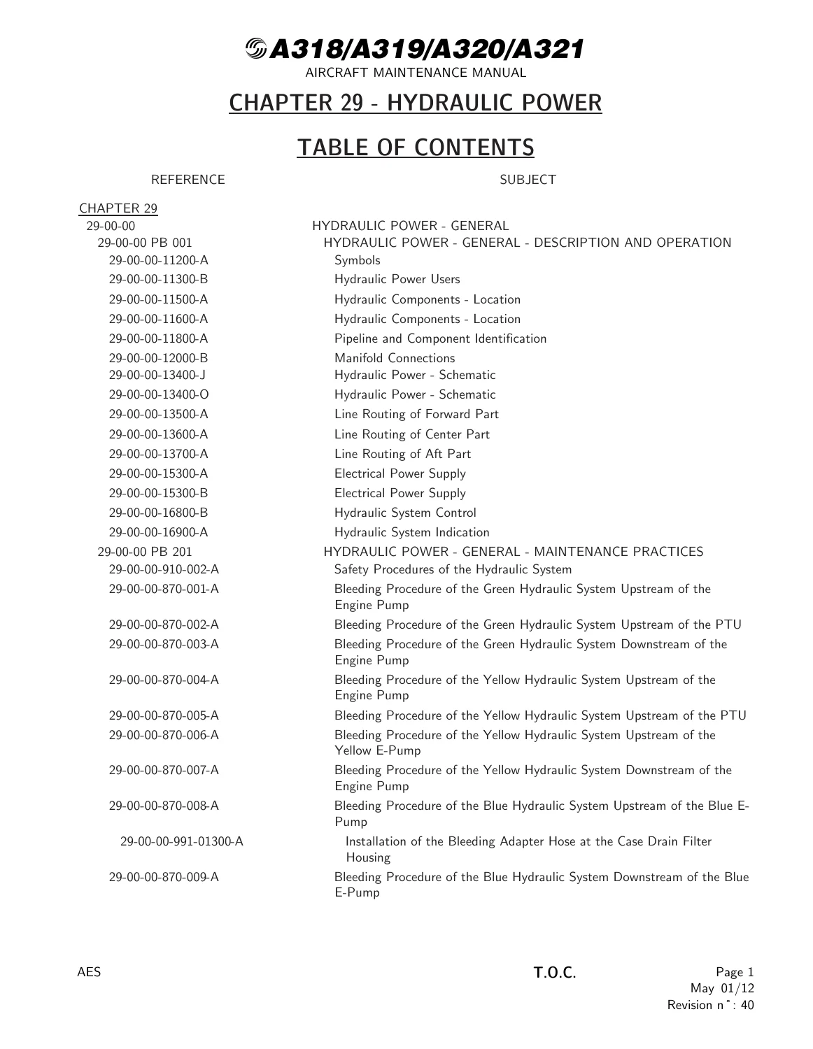
Table of Contentsp. 1
29-00 – HYDRAULIC POWER – GENERALp. 34
29-00-00 – HYDRAULIC POWER – GENERALp. 34
29-00-00 PB 001 CONF 00 – HYDRAULIC POWER – GENERAL – DESCRIPTION AND OPERATIONp. 34
Generalp. 34
System Descriptionp. 35
Power Supplyp. 37
Control and Indicationp. 38
Figure 29-00-00-11200-A – Symbolsp. 39
Figure 29-00-00-11300-B – Hydraulic Power Usersp. 40
Figure 29-00-00-11500-A – Hydraulic Components – Locationp. 41
Figure 29-00-00-11600-A – Hydraulic Components – Locationp. 42
Figure 29-00-00-11800-A – Pipeline and Component Identificationp. 43
Figure 29-00-00-12000-B – Manifold Connectionsp. 44
Figure 29-00-00-13400-J – Hydraulic Power – Schematicp. 45
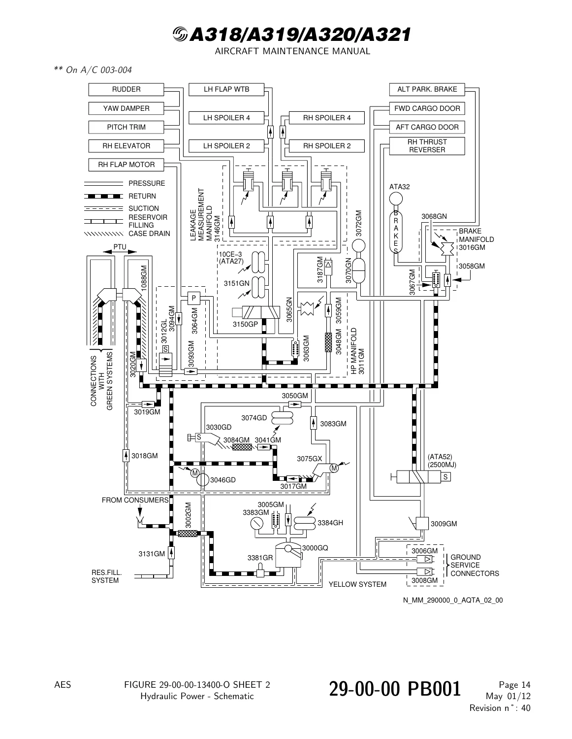
Figure 29-00-00-13400-O – Hydraulic Power – Schematicp. 46
Figure 29-00-00-13500-A – Line Routing of Forward Partp. 49
Figure 29-00-00-13600-A – Line Routing of Center Partp. 50
Figure 29-00-00-13700-A – Line Routing of Aft Partp. 51
Figure 29-00-00-15300-A – Electrical Power Supplyp. 52
Figure 29-00-00-15300-B – Electrical Power Supplyp. 53
Figure 29-00-00-16800-B – Hydraulic System Controlp. 54
Figure 29-00-00-16900-A – Hydraulic System Indicationp. 55
29-00-00 PB 201 CONF 00 – HYDRAULIC POWER – GENERAL – MAINTENANCE PRACTICESp. 56
29-00-00-910-002-A – Safety Procedures of the Hydraulic Systemp. 56
29-00-00-870-001-A – Bleeding Procedure of the Green Hydraulic System Upstream of the Engine Pumpp. 59
29-00-00-870-002-A – Bleeding Procedure of the Green Hydraulic System Upstream of the PTUp. 62
29-00-00-870-003-A – Bleeding Procedure of the Green Hydraulic System Downstream of the Engine Pumpp. 64
29-00-00-870-004-A – Bleeding Procedure of the Yellow Hydraulic System Upstream of the Engine Pumpp. 68
29-00-00-870-005-A – Bleeding Procedure of the Yellow Hydraulic System Upstream of the PTUp. 71
29-00-00-870-006-A – Bleeding Procedure of the Yellow Hydraulic System Upstream of the Yellow E-Pumpp. 73
29-00-00-870-007-A – Bleeding Procedure of the Yellow Hydraulic System Downstream of the Engine Pumpp. 75
29-00-00-870-008-A – Bleeding Procedure of the Blue Hydraulic System Upstream of the Blue E-Pumpp. 80
Figure 29-00-00-991-01300-A – Installation of the Bleeding Adapter Hose at the Case Drain Filter Housingp. 83
29-00-00-870-009-A – Bleeding Procedure of the Blue Hydraulic System Downstream of the Blue E-Pumpp. 84
29-00-00-864-001-A – Put the Related Hydraulic System in the Depressurized Configuration before Maintenance Actionp. 89
29-00-00-910-003-A – General Removal and Installation Procedure of the Check Valves in the Hydraulic Systemsp. 92
29-00-00-910-004-A – General Rules for Removal and Installation Procedures in the Hydraulic Systemsp. 97
Figure 29-00-00-991-01400-A – Example for a Hydraulic Bulkhead Fitting Installationp. 105
29-00-00-210-001-A – Check for Air in the Green/Blue/Yellow Hydraulic Systemp. 106
29-00-00 PB 501 CONF 00 – HYDRAULIC POWER – GENERAL – ADJUSTMENT/TESTp. 110
29-00-00-710-001-A – Integrity Test of the Hydraulic Powerp. 110
29-00-00 PB 601 CONF 00 – HYDRAULIC POWER – GENERAL – INSPECTION/CHECKp. 114
29-00-00-790-001-A – Check of the External Leaks of the Hydraulic Componentsp. 114
29-00-00-280-001-A – Check of the Internal Leakage of the Green Hydraulic Systemp. 124
Figure 29-00-00-991-00100-A – Green Hydraulic System – Central Sectionp. 130
Figure 29-00-00-991-00200-A – Green Hydraulic System – Rear Sectionp. 131
Figure 29-00-00-991-00300-B – Green Hydraulic System – Left Wing Sectionp. 132
Figure 29-00-00-991-00400-B – Green Hydraulic System – Right Wing Sectionp. 133
29-00-00-280-002-A – Check of the Internal Leakage of the Blue Hydraulic Systemp. 134
Figure 29-00-00-991-00500-B – Blue Hydraulic System – Central Sectionp. 140
Figure 29-00-00-991-00500-C – Blue Hydraulic System – Central Sectionp. 141
Figure 29-00-00-991-00600-B – Blue Hydraulic System – Rear Sectionp. 142
Figure 29-00-00-991-00600-C – Blue Hydraulic System – Rear Sectionp. 143
Figure 29-00-00-991-00700-B – Blue Hydraulic System – Left Wing Sectionp. 144
Figure 29-00-00-991-00700-C – Blue Hydraulic System – Left Wing Sectionp. 145
Figure 29-00-00-991-00800-B – Blue Hydraulic System – Right Wing Sectionp. 146
Figure 29-00-00-991-00800-C – Blue Hydraulic System – Right Wing Sectionp. 147
29-00-00-280-003-A – Check of the Internal Leakage of the Yellow Hydraulic Systemp. 148
Figure 29-00-00-991-00900-A – Yellow Hydraulic System – Central Sectionp. 153
Figure 29-00-00-991-01000-B – Yellow Hydraulic System – Rear Sectionp. 154
Figure 29-00-00-991-01100-B – Yellow Hydraulic System – Left Wing Sectionp. 155
Figure 29-00-00-991-01200-B – Yellow Hydraulic System – Right Wing Sectionp. 156
29-00-00-280-004-A – Check of the Internal Leakage of the Power Transfer Unit (PTU)p. 157
29-00-00-280-005-A – Check of the Green, Yellow or Blue Hydraulic System after Operation in an Overheat Conditionp. 159
29-00-00-280-006-A – Check of the Green or Yellow Hydraulic System after Engine Pump Failure or Operation in a Possible Cavitation Condition – with Ground Cart Availablep. 160
29-00-00-280-006-A-01 – Check of the Green or Yellow Hydraulic System after Engine Pump Failure or Operation in a Possible Cavitation Condition – Ground Cart not Availablep. 162
29-00-00-210-003-A – Detailed Visual Inspection for Correct Installation of the Green and Yellow System Hydraulic Pipes in the MLG Bayp. 164
Figure 29-00-00-991-03300-A – Green Hydraulic System – Main Landing Gear (MLG) Bayp. 167
Figure 29-00-00-991-03400-A – Yellow Hydraulic System – Main Landing Gear (MLG) Bayp. 169
29-10 – MAIN HYDRAULIC POWERp. 170
29-10-00 – MAIN HYDRAULIC POWERp. 170
29-10-00 PB 001 CONF 00 – MAIN HYDRAULIC POWER – DESCRIPTION AND OPERATIONp. 170
Generalp. 170
29-10-00 PB 201 CONF 00 – MAIN HYDRAULIC POWER – MAINTENANCE PRACTICESp. 171
29-10-00-864-001-A – Depressurize the Green Hydraulic Systemp. 171
29-10-00-864-002-A – Depressurize the Yellow Hydraulic Systemp. 173
29-10-00-864-003-A – Depressurize the Blue Hydraulic Systemp. 176
29-10-00-864-004-A – Depressurize the Brake Systemp. 178
Figure 29-10-00-991-00800-A – Depressurization Pushbutton of the Brake Relief Valve (3067GM)p. 181
Figure 29-10-00-991-00800-B – Depressurization Pushbutton of the Brake Relief Valve (3067GM)p. 182
29-10-00-863-001-A – Pressurize the Green Hydraulic Systemp. 183
29-10-00-863-002-A – Pressurize the Yellow Hydraulic Systemp. 187
29-10-00-863-003-A – Pressurize the Blue Hydraulic System with a Ground Power Supplyp. 191
29-10-00-863-003-A-01 – Pressurize the Blue Hydraulic System with the Blue Electric Pumpp. 194
29-10-00-680-001-A – Drainage of the Reservoir of the Green Hydraulic Systemp. 196
Figure 29-10-00-991-00400-A – Drain Valve Locationsp. 199
Figure 29-10-00-991-00400-B – Drain Valve Locationsp. 200
29-10-00-680-002-A – Drainage of the Reservoir of the Yellow Hydraulic Systemp. 201
29-10-00-680-003-A – Drainage of the Reservoir of the Blue Hydraulic Systemp. 204
29-10-00 PB 401 CONF 00 – MAIN HYDRAULIC POWER – DEACTIVATION/REACTIVATIONp. 207
29-10-00-040-001-A – Deactivation of the Case Drain Filter of the Engine Driven Pump of the Green Hydraulic Systemp. 207
Figure 29-10-00-991-00200-B – Case Drain Filters of the Engine Driven Pumpsp. 210
29-10-00-440-001-A – Reactivation of the Case Drain Filter of the Engine Driven Pump of the Green Hydraulic Systemp. 211
29-10-00-040-002-A – Deactivation of the Case Drain Filter of the Engine Driven Pump of the Yellow Hydraulic Systemp. 214
29-10-00-440-002-A – Reactivation of the Case Drain Filter of the Engine Driven Pump of the Yellow Hydraulic Systemp. 217
29-10-00-040-003-A – Deactivation of the Case Drain Filter of the Electric Pump of the Blue Hydraulic Systemp. 220
Figure 29-10-00-991-00300-A – Case Drain Filter of the Electric Pump of the Blue Hydraulic Systemp. 223
29-10-00-440-003-A – Reactivation of the Case Drain Filter of the Electric Pump of the Blue Hydraulic Systemp. 224
29-10-00-040-004-A – Deactivation of the Green Power Accumulatorp. 227
Figure 29-10-00-991-01100-B – Green Power Accumulator (1070GM)p. 231
29-10-00-440-004-A – Reactivation of the Green Power Accumulatorp. 232
29-10-00-040-005-A – Deactivation of the Blue Power Accumulatorp. 236
Figure 29-10-00-991-01200-A – Blue Power Accumulator (2070GM)p. 240
29-10-00-440-005-A – Reactivation of the Blue Power Accumulatorp. 241
29-10-00-040-006-A – Deactivation of the Yellow Power Accumulatorp. 245
Figure 29-10-00-991-01300-A – Yellow Power Accumulator (3070GM)p. 249
29-10-00-440-006-A – Reactivation of the Yellow Power Accumulatorp. 250
29-10-00-040-007-A – Leak Check on the Accumulator Nitrogen Charging-Circuit for Hydraulic Leakagesp. 254
29-10-00 PB 501 CONF 00 – MAIN HYDRAULIC POWER – ADJUSTMENT/TESTp. 257
29-10-00-710-001-A – Operational Check of Hydraulic Fire Shut Off Valves and Associated Indicating Systemp. 257
29-10-00-720-001-A – Functional Check of Hydraulic Fire Shut-Off Valvesp. 262
29-10-00-720-002-A – Functional Check of Priority Valves in Green, Blue and Yellow Systemp. 267
29-10-00-710-004-A – Operational Check of EDP Depressurizationp. 272
29-10-00 PB 601 CONF 00 – MAIN HYDRAULIC POWER – INSPECTION/CHECKp. 275
29-10-00-200-001-A – Check Fluid Level on Reservoir Indicatorsp. 275
29-10-00-200-002-A – Check Reservoir Air Pressure on Reservoir Gaugep. 278
29-10-00-200-008-A – Check Nitrogen Charge Pressure on Hydraulic Power Accumulatorsp. 281
Figure 29-10-00-991-01000-A – Pressure Valuep. 285
29-10-00-200-006-A – Check Clogging Indicator on Engine-Driven Pump (EDP) Case Drain Filterp. 286
Figure 29-10-00-991-00500-A – EDP Case-Drain Filtersp. 288
29-10-00-220-001-A – Functional Check to Monitor Internal Leak Rate of Yellow and Green Hydraulic Systemsp. 289
29-10-00-220-002-A – Functional Check to Monitor Internal Leak Rate of Blue Hydraulic Systemp. 293
29-10-00-210-002-A – Check of the Clogging Indicators of the Hydraulic System Filters (Other than the two Case Drain Filters of the Engine-Driven Pumps)p. 295
Figure 29-10-00-991-00900-A – Location of the Filtersp. 302
29-10-00-200-025-A – Visual Check of High and Low Pressure Manifolds and Ground Service Panels and Manifolds for Signs of External Leakagep. 303
Figure 29-10-00-991-02400-A – Green Hydraulic System – High Pressure Manifoldp. 306
Figure 29-10-00-991-02700-A – Green Hydraulic System – Ground Leakage Manifoldp. 308
Figure 29-10-00-991-02500-A – Blue Hydraulic System – High Pressure Manifoldp. 310
Figure 29-10-00-991-02800-A – Blue Hydraulic System – Ground Leakage Manifoldp. 312
Figure 29-10-00-991-02600-A – Yellow Hydraulic System – High Pressure Manifoldp. 314
Figure 29-10-00-991-02900-A – Yellow Hydraulic System – Ground Leakage Manifoldp. 316
29-11 – GREEN MAIN HYDRAULIC POWERp. 318
29-11-00 – GREEN MAIN HYDRAULIC POWERp. 318
29-11-00 PB 001 CONF 00 – GREEN MAIN HYDRAULIC POWER – DESCRIPTION AND OPERATIONp. 318
Generalp. 318
Component Locationp. 319
System Descriptionp. 321
Power Supplyp. 325
Component Descriptionp. 326
Operationp. 333
Figure 29-11-00-12400-B – Green Hydraulic System – Component Location – Sheet 1p. 334
Figure 29-11-00-12500-C – Component Location – Sheet 2p. 335
Figure 29-11-00-12500-D – Green Hydraulic System – Component Location – Sheet 2p. 336
Figure 29-11-00-12600-A – Green Hydraulic System – Component Locationp. 337
Figure 29-11-00-12700-A – Green Hydraulic System FR44 – Component Locationp. 338
Figure 29-11-00-12800-B – Component Locationp. 339
Figure 29-11-00-12900-A – Component Locationp. 340
Figure 29-11-00-13000-A – Component Locationp. 341
Figure 29-11-00-13100-A – Component Locationp. 342
Figure 29-11-00-13200-A – Green HYD Equipment on the Left Wing – Component Locationp. 343
Figure 29-11-00-13300-A – Green HYD Equipment on the Right Wing – Component Locationp. 344
Figure 29-11-00-14700-C – Green Hydraulic System – Schematicp. 345
Figure 29-11-00-17400-A – Power Supply and Control of the Green Systemp. 346
Figure 29-11-00-17500-B – Power Supply of the Fire Valvep. 347
Figure 29-11-00-18900-A – Reservoirp. 348
Figure 29-11-00-18900-B – Reservoirp. 349
Figure 29-11-00-19500-B – Engine Pump Fire Valvep. 350
Figure 29-11-00-20100-A – Engine-Driven Pump (VICKERS)p. 351
Figure 29-11-00-20200-A – Engine-Driven Pump (VICKERS) – Schematicp. 352
Figure 29-11-00-21500-B – System Accumulatorp. 353
Figure 29-11-00-22300-A – HP and Case Drain Filterp. 354
Figure 29-11-00-23500-A – LP Filterp. 355
Figure 29-11-00-24000-A – Relief Valvep. 356
Figure 29-11-00-24500-A – Priority Valvep. 357
Figure 29-11-00-25000-A – Sampling Valvep. 358
Figure 29-11-00-25500-B – Check Valvesp. 359
Figure 29-11-00-26200-A – Compensated Slidep. 360
29-11-00 PB 501 CONF 00 – GREEN MAIN HYDRAULIC POWER – ADJUSTMENT/TESTp. 361
29-11-00-710-001-A – Operational Test of the Green Hydraulic Systemp. 361
29-11-14 – MANIFOLD – MAIN HPp. 364
29-11-14 PB 401 CONF 00 – MANIFOLD – MAIN HP – REMOVAL/INSTALLATIONp. 364
29-11-14-000-001-A – Removal of the HP Manifold of the Green Hydraulic Systemp. 364
Figure 29-11-14-991-00100-B – HP Manifoldp. 367
Figure 29-11-14-991-00100-E – HP Manifoldp. 368
29-11-14-400-001-A – Installation of the HP Manifold of the Green Hydraulic Systemp. 369
29-11-15 – MANIFOLD – PTUp. 381
29-11-15 PB 401 CONF 00 – MANIFOLD – PTU – REMOVAL/INSTALLATIONp. 381
29-11-15-000-001-A – Removal of the Power Transfer Unit (PTU) Manifold of the Green Hydraulic Systemp. 381
Figure 29-11-15-991-00100-A – PTU Manifoldp. 384
Figure 29-11-15-991-00100-B – PTU Manifoldp. 385
29-11-15-400-001-A – Installation of the Power Transfer Unit (PTU) Manifold of the Green Hydraulic Systemp. 386
29-11-17 – PRESSURE SWITCH – ENGINE PUMPp. 395
29-11-17 PB 401 CONF 13 – PRESSURE SWITCH – ENGINE PUMP – REMOVAL/INSTALLATIONp. 395
29-11-17-000-010-A – Removal of the Engine Pump Pressure Switchp. 395
Figure 29-11-17-991-15000-A – Engine Pump Pressure Switchp. 399
Figure 29-11-17-991-15000-B – Engine Pump Pressure Switchp. 400
29-11-17-400-010-A – Installation of the Engine Pump Pressure Switchp. 401
29-11-21 – PRESSURE GAGE – ACCUMULATOR AIR, GREEN POWERp. 407
29-11-21 PB 401 CONF 00 – PRESSURE GAGE – ACCUMULATOR AIR, GREEN POWER – REMOVAL/INSTALLATIONp. 407
29-11-21-000-001-A – Removal of the Accumulator-Air Pressure Gagep. 407
Figure 29-11-21-991-00100-B – Pressure Gagep. 409
29-11-21-400-001-A – Installation of the Accumulator-Air Pressure Gagep. 410
29-11-22 – VALVE – CHARGING, GREEN POWER ACCUMULATORp. 413
29-11-22 PB 401 CONF 00 – VALVE – CHARGING, GREEN POWER ACCUMULATOR – REMOVAL/INSTALLATIONp. 413
29-11-22-000-001-A – Removal of the Accumulator-Gas Charging Valvep. 413
Figure 29-11-22-991-00100-B – Gas Charging Valvep. 415
29-11-22-400-001-A – Installation of the Accumulator-Gas Charging Valvep. 416
29-11-32 – RELIEF VALVEp. 419
29-11-32 PB 401 CONF 00 – RELIEF VALVE – REMOVAL/INSTALLATIONp. 419
29-11-32-000-001-A – Removal of the Pressure Relief Valve of the Green Hydraulic Systemp. 419
Figure 29-11-32-991-00100-B – Pressure Relief Valvep. 421
Figure 29-11-32-991-00100-C – Pressure Relief Valvep. 422
29-11-32-400-001-A – Installation of the Pressure Relief Valve of the Green Hydraulic Systemp. 423
29-11-33 – PRIORITY VALVEp. 427
29-11-33 PB 401 CONF 00 – PRIORITY VALVE – REMOVAL/INSTALLATIONp. 427
29-11-33-000-001-A – Removal of the Priority Valve of the Green Hydraulic Systemp. 427
Figure 29-11-33-991-00100-A – Priority Valvep. 429
Figure 29-11-33-991-00100-B – Priority Valvep. 430
29-11-33-400-001-A – Installation of the Priority Valve of the Green Hydraulic Systemp. 431
29-11-34 – VALVE – FLUID SAMPLINGp. 435
29-11-34 PB 401 CONF 00 – VALVE – FLUID SAMPLING – REMOVAL/INSTALLATIONp. 435
29-11-34-000-001-A – Removal of the Fluid Sampling Valve of the Green Hydraulic Systemp. 435
Figure 29-11-34-991-00100-B – Fluid Sampling Valvep. 437
Figure 29-11-34-991-00100-C – Fluid Sampling Valvep. 438
29-11-34-400-001-A – Installation of the Fluid Sampling Valve of the Green Hydraulic Systemp. 439
29-11-36 – CHECK VALVE – ENG 1 PUMP DELIVERYp. 443
29-11-36 PB 401 CONF 00 – CHECK VALVE – ENG 1 PUMP DELIVERY – REMOVAL/INSTALLATIONp. 443
29-11-36-000-001-A – Removal of the Engine 1 Green Hydraulic Pump Delivery Check Valvep. 443
Figure 29-11-36-991-00100-A – Check Valve – Engine 1 Pump Deliveryp. 445
29-11-36-400-001-A – Installation of the Engine 1 Green Hydraulic Pump Delivery Check Valvep. 446
29-11-37 – CHECK VALVE – ENGINE 1 PUMP CASE DRAINp. 449
29-11-37 PB 401 CONF 00 – CHECK VALVE – ENGINE 1 PUMP CASE DRAIN – REMOVAL/INSTALLATIONp. 449
29-11-37-000-001-A – Removal of the Green Engine 1 Pump Case Drain Check Valvep. 449
Figure 29-11-37-991-00100-A – Green Engine 1 Pump Case Drain Check Valvep. 451
29-11-37-400-001-A – Installation of the Green Engine 1 Pump Case Drain Check Valvep. 452
29-11-39 – COUPLING HALF – QUICK DISCONNECT ENGINE 1 PUMP SUCTIONp. 455
29-11-39 PB 401 CONF 13 – COUPLING HALF – SELF SEALING GREEN PUMP SUCTION – REMOVAL/INSTALLATIONp. 455
29-11-39-000-802-A – Removal of the Self Sealing Half-Coupling of the Green Pump Suction (1700GM)p. 455
Figure 29-11-39-991-90200-A – Self Sealing Half-Coupling of the Green Pump Suctionp. 457
29-11-39-400-802-A – Installation of the Self Sealing Half-Coupling of the Green Pump Suction (1700GM)p. 458
29-11-41 – RESERVOIRp. 462
29-11-41 PB 401 CONF 00 – RESERVOIR – REMOVAL/INSTALLATIONp. 462
29-11-41-000-001-A – Removal of the Green Hydraulic Reservoirp. 462
Figure 29-11-41-991-00100-B – Reservoir of the Green Hydraulic System (Sheet 1)p. 465
Figure 29-11-41-991-00200-A – Reservoir of the Green Hydraulic System (Sheet 2)p. 466
Figure 29-11-41-991-00100-C – Reservoir of the Green Hydraulic System (Sheet 1)p. 467
Figure 29-11-41-991-00200-B – Reservoir of the Green Hydraulic System (Sheet 2)p. 468
29-11-41-400-001-A – Installation of the Green Hydraulic Reservoirp. 469
29-11-41-000-002-A – Removal of the Quantity Indicator of the Green Hydraulic Reservoirp. 475
Figure 29-11-41-991-00300-A – Quantity Indicator and Low Level Switchp. 477
Figure 29-11-41-991-00300-B – Quantity Indicator and Low Level Switchp. 478
29-11-41-400-002-A – Installation of the Quantity Indicator of the Green Hydraulic Reservoirp. 479
29-11-41-000-003-A – Removal of the Low Level Switch of the Green Hydraulic Reservoirp. 483
29-11-41-400-003-A – Installation of the Low Level Switch of the Green Hydraulic Reservoirp. 485
29-11-41-000-004-A – Removal of the Drain Valve of the Green Hydraulic Reservoirp. 489
Figure 29-11-41-991-00500-A – Drain Valvep. 491
Figure 29-11-41-991-00500-B – Drain Valvep. 492
29-11-41-400-004-A – Installation of the Drain Valve of the Green Hydraulic Reservoirp. 493
29-11-42 – ACCUMULATOR – GREEN POWERp. 497
29-11-42 PB 401 CONF 00 – ACCUMULATOR – GREEN POWER – REMOVAL/INSTALLATIONp. 497
29-11-42-000-001-A – Removal of the Green Power Accumulatorp. 497
Figure 29-11-42-991-00100-B – Green Power Accumulatorp. 499
29-11-42-400-001-A – Installation of the Green Power Accumulatorp. 500
29-11-43 – FILTER – ENGINE PUMP CASE DRAINp. 504
29-11-43 PB 301 CONF 13 – FILTER – ENGINE PUMP CASE DRAIN – SERVICINGp. 504
29-11-43-610-010-A – Servicing of the Engine-Pump Case-Drain Filterp. 504
Figure 29-11-43-991-15100-A – Engine-Pump Case-Drain Filterp. 508
29-11-43 PB 401 CONF 13 – FILTER – ENGINE PUMP CASE DRAIN – REMOVAL/INSTALLATIONp. 509
29-11-43-000-010-A – Removal of the Engine-Pump Case-Drain Filterp. 509
Figure 29-11-43-991-15000-A – Engine-Pump Case-Drain Filterp. 512
29-11-43-400-010-A – Installation of the Engine-Pump Case-Drain Filterp. 513
29-11-43-000-011-A – Removal of the Differential Pressure Indicator (DPI)p. 517
Figure 29-11-43-991-15200-A – Differential Pressure Indicator (DPI)p. 520
29-11-43-400-011-A – Installation of the Differential Pressure Indicator (DPI)p. 521
29-11-44 – FILTER – LPp. 524
29-11-44 PB 301 CONF 00 – FILTER – LP – SERVICINGp. 524
29-11-44-610-001-A – Servicing of the LP-Filterp. 524
Figure 29-11-44-991-00100-A – LP Filterp. 527
29-11-44-960-001-A – Replacement of the Clogging Indicatorp. 528
29-11-44 PB 401 CONF 00 – FILTER – LP – REMOVAL/INSTALLATIONp. 531
29-11-44-000-001-A – Removal of the Low Pressure Filter-Assemblyp. 531
Figure 29-11-44-991-00200-A – Low Pressure Filter-Assemblyp. 534
29-11-44-400-001-A – Installation of the Low Pressure Filter-Assemblyp. 535
29-11-45 – FILTER – HPp. 541
29-11-45 PB 301 CONF 00 – FILTER – HP – SERVICINGp. 541
29-11-45-610-001-A – Servicing of the HP-Filterp. 541
Figure 29-11-45-991-00100-A – HP Filterp. 545
29-11-45-960-001-A – Replacement of the Clogging Indicatorp. 546
29-11-47 – SLIDE – COMPENSATEDp. 549
29-11-47 PB 401 CONF 00 – SLIDE – COMPENSATED – REMOVAL/INSTALLATIONp. 549
29-11-47-000-001-A – Removal of the Compensated Slidep. 549
Figure 29-11-47-991-00100-A – Compensated Slide 1010GMp. 552
29-11-47-400-001-A – Installation of the Compensated Slidep. 553
29-11-48 – CHECK VALVE – WTBp. 557
29-11-48 PB 401 CONF 00 – CHECK VALVE – WTB – REMOVAL/INSTALLATIONp. 557
29-11-48-000-001-A – Removal of the Check Valvep. 557
Figure 29-11-48-991-00100-A – Slat WTB Check Valves 1410GM(1411GM)p. 560
29-11-48-400-001-A – Installation of the Check Valvep. 561
29-11-48-000-002-A – Removal of the Check Valvep. 566
Figure 29-11-48-991-00200-A – Flap WTB Check Valve 1170GMp. 569
29-11-48-400-002-A – Installation of the Check Valvep. 570
29-11-49 – HYDRAULIC TUBES – ENGINE 1p. 574
29-11-49 PB 401 CONF 13 – HYDRAULIC TUBES – ENGINE 1 – REMOVAL/INSTALLATIONp. 574
29-11-49-000-010-A – Removal of the Hydraulic Suction Tubesp. 574
Figure 29-11-49-991-15000-A – Hydraulic Tube Detailsp. 577
Figure 29-11-49-991-15100-A – Hydraulic Tube Detailsp. 578
Figure 29-11-49-991-15200-A – Hydraulic Tube Detailsp. 579
29-11-49-400-010-A – Installation of the Hydraulic Suction Tubesp. 580
29-11-49-000-011-A – Removal of the Hydraulic Pressure Tubesp. 585
29-11-49-400-011-A – Installation of the Hydraulic Pressure Tubesp. 589
29-11-49-000-012-A – Removal of the Hydraulic Case Drain Tubesp. 595
29-11-49-400-012-A – Installation of the Hydraulic Case Drain Tubesp. 598
29-11-49-000-013-A – Removal of the Pressure/Suction/Case Drain/Return Piping of the Green Hydraulic System in the Engine Pylonp. 603
Figure 29-11-49-991-15400-A – Middle Pressure/Suction/Case Drain/Return Piping of the Green Hydraulic System in the Engine Pylonp. 609
Figure 29-11-49-991-15500-B – Forward Pressure/Suction/Case Drain/Return Piping of the Green Hydraulic System in the Engine Pylonp. 611
Figure 29-11-49-991-15600-A – Aft Pressure/Suction/Case Drain/Return Piping of the Green Hydraulic System in the Engine Pylonp. 612
29-11-49-400-013-A – Installation of the Pressure/Suction/Case Drain/Return Piping of the Green Hydraulic System in the Engine Pylonp. 613
29-11-49 PB 601 CONF 13 – HYDRAULIC TUBES – ENGINE 1 – INSPECTION/CHECKp. 622
29-11-49-200-010-A – Visual Inspection of the Hydraulic Hoses and Tubesp. 622
Figure 29-11-49-991-15300-A – Engine Hydraulic Tubesp. 626
29-11-51 – PUMP – ENGINEp. 627
29-11-51 PB 201 CONF 00 – PUMP – ENGINE – MAINTENANCE PRACTICESp. 627
29-11-51-860-040-A – Hydraulic Maintenance Procedure After an Engine Installation (With Engine Pump Installed) or After an Engine Pump Installationp. 627
Figure 29-11-51-991-00100-B – Green Engine Pumpp. 630
29-11-51 PB 401 CONF 13 – PUMP – ENGINE – REMOVAL/INSTALLATIONp. 631
29-11-51-000-010-A – Removal of the Engine Pumpp. 631
Figure 29-11-51-991-15000-A – Engine Pumpp. 634
29-11-51-400-010-A – Installation of the Engine Pumpp. 635
29-11-51-000-011-A – Removal of the Engine Pump Solenoid-Valvep. 640
Figure 29-11-51-991-16000-A – Engine Pump Solenoid-Valvep. 643
29-11-51-400-011-A – Installation of the Engine Pump Solenoid-Valvep. 644
29-11-52 – VALVE – ENGINE PUMP FIREp. 648
29-11-52 PB 401 CONF 00 – VALVE – ENGINE PUMP FIRE – REMOVAL/INSTALLATIONp. 648
29-11-52-000-001-A – Removal of the Engine Pump Fire-Valvep. 648
Figure 29-11-52-991-00100-A – Engine Pump Fire-Valve (1046GK)p. 651
29-11-52-400-001-A – Installation of the Engine Pump Fire-Valvep. 653
29-11-52-000-002-A – Removal of the Actuator – Engine Pump Fire-Valvep. 657
Figure 29-11-52-991-00200-B – Actuator – Engine Pump Fire-Valve (1046GK)p. 660
29-11-52-400-002-A – Installation of the Actuator – Engine Pump Fire-Valvep. 661
29-11-52 PB 601 CONF 00 – VALVE – ENGINE PUMP FIRE – INSPECTION/CHECKp. 665
29-11-52-200-001-A – Inspection of the Engine Pump Fire-Valvep. 665
Figure 29-11-52-991-00300-B – Engine Pump Fire-Valve (1046GK)p. 668
29-11-63 – GROUND CONNECTOR – SELF-SEALINGp. 669
29-11-63 PB 401 CONF 00 – GROUND CONNECTOR – SELF-SEALING – REMOVAL/INSTALLATIONp. 669
29-11-63-000-001-A – Removal of the Self-Sealing Ground Connectors of the Green Hydraulic Systemp. 669
Figure 29-11-63-991-00100-A – Self-Sealing Ground Connectors of the Green Hydraulic Systemp. 671
29-11-63-400-001-A – Installation of the Self-Sealing Ground Connectors of the Green Hydraulic Systemp. 672
29-12 – BLUE MAIN HYDRAULIC POWERp. 675
29-12-00 – BLUE MAIN HYDRAULIC POWERp. 675
29-12-00 PB 001 CONF 00 – BLUE MAIN HYDRAULIC POWER – DESCRIPTION AND OPERATIONp. 675
Generalp. 675
Component Locationp. 676
System Descriptionp. 678
Power Supplyp. 682
Component Descriptionp. 683
Operationp. 688
Figure 29-12-00-12300-C – Blue Hydraulic System – Component Location – Sheet 1p. 689
Figure 29-12-00-12300-E – Component Location – Sheet 1p. 690
Figure 29-12-00-12400-A – Blue Hydraulic System – Component Location – Sheet 2p. 691
Figure 29-12-00-12500-A – Component Location – Sheet 3p. 692
Figure 29-12-00-12500-C – Blue Hydraulic System – Component Location – Sheet 3p. 693
Figure 29-12-00-12600-A – Reservoir, LP Filter and Check Valves – Component Locationp. 694
Figure 29-12-00-12700-A – Ground Service Panel – Component Locationp. 695
Figure 29-12-00-12800-B – Electric Components – Component Locationp. 696
Figure 29-12-00-12900-A – Blue HYD Equipment on Left Wing – Component Locationp. 697
Figure 29-12-00-13000-A – Blue HYD Equipment on Right Wing – Component Locationp. 698
Figure 29-12-00-14300-G – Blue Hydraulic System – Schematicp. 699
Figure 29-12-00-14300-H – Blue Hydraulic System – Schematicp. 700
Figure 29-12-00-16400-C – Blue Electric Pump – Control and Monitoring (Sheet 1/2)p. 701
Figure 29-12-00-16500-A – Blue Electric Pump – Control and Monitoring (Sheet 2/2)p. 702
Figure 29-12-00-17900-A – Reservoir 2000GQp. 703
Figure 29-12-00-18400-C – Electric Pump 2075GJp. 704
Figure 29-12-00-19000-A – Current Transformer 2706GJp. 705
Figure 29-12-00-19500-A – Current Unbalance Detector 2707GJp. 706
Figure 29-12-00-21800-A – Case Drain and LP Filters 2084GM and 2002GMp. 707
29-12-00 PB 501 CONF 00 – BLUE MAIN HYDRAULIC POWER – ADJUSTMENT/TESTp. 708
29-12-00-710-001-A – Functional Check of Blue Electrical Pump Pressure by Reading ECAM Indicationp. 708
29-12-00-710-002-A – Operational Test of the Phase Unbalance Detector and the Current Transformer of the Blue Hydraulic Systemp. 711
Figure 29-12-00-991-00100-A – Phase Unbalance Detectorp. 715
29-12-14 – MANIFOLD – MAIN HPp. 716
29-12-14 PB 401 CONF 00 – MANIFOLD – MAIN HP – REMOVAL/INSTALLATIONp. 716
29-12-14-000-001-A – Removal of the HP Manifold of the Blue Hydraulic Systemp. 716
Figure 29-12-14-991-00100-A – HP Manifold – Sheet 1p. 720
Figure 29-12-14-991-00200-A – HP Manifold – Sheet 2p. 721
Figure 29-12-14-991-00100-D – HP Manifold – Sheet 1p. 722
Figure 29-12-14-991-00200-B – HP Manifold – Sheet 2p. 723
29-12-14-400-001-A – Installation of the HP Manifold of the Blue Hydraulic Systemp. 724
29-12-15 – CURRENT TRANSFORMER – BLUE ELECTRIC PUMPp. 738
29-12-15 PB 401 CONF 00 – CURRENT TRANSFORMER – BLUE ELECTRIC PUMP – REMOVAL/INSTALLATIONp. 738
29-12-15-000-001-A – Removal of the Blue Electric-Pump Current Transformerp. 738
Figure 29-12-15-991-00100-A – Blue Electric-Pump Current Transformerp. 740
29-12-15-400-001-A – Installation of the Blue Electric-Pump Current Transformerp. 741
29-12-17 – PRESSURE SWITCH – ELECTRIC PUMPp. 744
29-12-17 PB 401 CONF 00 – PRESSURE SWITCH – ELECTRIC PUMP – REMOVAL/INSTALLATIONp. 744
29-12-17-000-001-A – Removal of the Electric Pump Pressure-Switchp. 744
Figure 29-12-17-991-00100-A – Electric Pump Pressure-Switchp. 746
29-12-17-400-001-A – Installation of the Electric Pump Pressure-Switchp. 747
29-12-18 – DETECTOR – PHASE UNBALANCE BLUE ELECTRIC PUMPp. 750
29-12-18 PB 401 CONF 00 – DETECTOR – PHASE UNBALANCE BLUE ELECTRIC PUMP – REMOVAL/INSTALLATIONp. 750
29-12-18-000-001-A – Removal of the Blue Electric Pump Phase-Unbalance Detectorp. 750
Figure 29-12-18-991-00100-A – Blue Electric Pump Phase-Unbalance Detectorp. 752
29-12-18-400-001-A – Installation of the Blue Electric Pump Phase-Unbalance Detectorp. 753
29-12-21 – PRESSURE GAGE – ACCUMULATOR AIR, BLUE POWERp. 755
29-12-21 PB 401 CONF 00 – PRESSURE GAGE – ACCUMULATOR AIR, BLUE POWER – REMOVAL/INSTALLATIONp. 755
29-12-21-000-001-A – Removal of the Accumulator-Air Pressure Gagep. 755
Figure 29-12-21-991-00100-A – Pressure Gagep. 757
29-12-21-400-001-A – Installation of the Accumulator-Air Pressure Gagep. 758
29-12-22 – VALVE – CHARGING, BLUE POWER ACCUMULATORp. 761
29-12-22 PB 401 CONF 00 – VALVE – CHARGING, BLUE POWER ACCUMULATOR – REMOVAL/INSTALLATIONp. 761
29-12-22-000-001-A – Removal of the Accumulator-Gas Charging Valvep. 761
Figure 29-12-22-991-00100-A – Gas Charging Valvep. 763
29-12-22-400-001-A – Installation of the Accumulator-Gas Charging Valvep. 764
29-12-32 – RELIEF VALVEp. 767
29-12-32 PB 401 CONF 00 – RELIEF VALVE – REMOVAL/INSTALLATIONp. 767
29-12-32-000-001-A – Removal of the Pressure Relief Valve of the Blue Hydraulic Systemp. 767
Figure 29-12-32-991-00100-B – Pressure Relief Valvep. 769
Figure 29-12-32-991-00100-C – Pressure Relief Valvep. 770
29-12-32-400-001-A – Installation of the Pressure Relief Valve of the Blue Hydraulic Systemp. 771
29-12-33 – PRIORITY VALVEp. 775
29-12-33 PB 401 CONF 00 – PRIORITY VALVE – REMOVAL/INSTALLATIONp. 775
29-12-33-000-001-A – Removal of the Priority Valve of the Blue Hydraulic Systemp. 775
Figure 29-12-33-991-00100-A – Priority Valvep. 777
Figure 29-12-33-991-00100-B – Priority Valvep. 778
29-12-33-400-001-A – Installation of the Priority Valve of the Blue Hydraulic Systemp. 779
29-12-34 – VALVE – FLUID SAMPLINGp. 783
29-12-34 PB 401 CONF 00 – VALVE – FLUID SAMPLING – REMOVAL/INSTALLATIONp. 783
29-12-34-000-001-A – Removal of the Fluid Sampling Valve of the Blue Hydraulic Systemp. 783
Figure 29-12-34-991-00100-A – Fluid Sampling Valvep. 785
Figure 29-12-34-991-00100-B – Fluid Sampling Valvep. 786
29-12-34-400-001-A – Installation of the Fluid Sampling Valve of the Blue Hydraulic Systemp. 787
29-12-35 – VALVE – DRAINp. 790
29-12-35 PB 401 CONF 00 – VALVE – DRAIN – REMOVAL/INSTALLATIONp. 790
29-12-35-000-001-A – Removal of the Reservoir Drain Valvep. 790
Figure 29-12-35-991-00100-A – Reservoir Drain Valvep. 792
29-12-35-400-001-A – Installation of the Reservoir Drain Valvep. 793
29-12-36 – CHECK VALVE, BLUE ELEC PUMP DELIVERYp. 796
29-12-36 PB 401 CONF 00 – CHECK VALVE, BLUE ELEC PUMP DELIVERY – REMOVAL/INSTALLATIONp. 796
29-12-36-000-001-A – Removal of the Check Valve of the Blue Electric Pumpp. 796
Figure 29-12-36-991-00100-A – Check Valve of the Blue Electric Pumpp. 798
29-12-36-400-001-A – Installation of the Check Valve of the Blue Electric Pumpp. 799
29-12-37 – CHECK VALVE – WTBp. 802
29-12-37 PB 401 CONF 00 – CHECK VALVE – WTB – REMOVAL/INSTALLATIONp. 802
29-12-37-000-001-A – Removal of the Check Valvep. 802
Figure 29-12-37-991-00100-A – Slat WTB Check Valve 2410GM (2411GM)p. 805
29-12-37-400-001-A – Installation of the Check Valvep. 806
29-12-37-000-002-A – Removal of the Check Valvep. 810
Figure 29-12-37-991-00200-B – Flap WTB Check Valve 2170GMp. 813
Figure 29-12-37-991-00300-A – Flap WTB Check Valve 2405GMp. 814
29-12-37-400-002-A – Installation of the Check Valvep. 815
29-12-38 – CHECK VALVE-RAT DELIVERYp. 820
29-12-38 PB 401 CONF 00 – CHECK VALVE-RAT DELIVERY – REMOVAL/INSTALLATIONp. 820
29-12-38-000-001-A – Removal of the Check Valvep. 820
Figure 29-12-38-991-00100-A – RAT Delivery Check Valvep. 822
29-12-38-400-001-A – Installation of the Check Valvep. 823
29-12-41 – RESERVOIRp. 826
29-12-41 PB 401 CONF 00 – RESERVOIR – REMOVAL/INSTALLATIONp. 826
29-12-41-000-001-A – Removal of the Blue Hydraulic Reservoirp. 826
Figure 29-12-41-991-00100-D – Reservoir of the Blue Hydraulic Systemp. 829
Figure 29-12-41-991-00200-A – Reservoir of the Blue Hydraulic Systemp. 830
29-12-41-400-001-A – Installation of the Blue Hydraulic Reservoirp. 831
29-12-41-000-002-A – Removal of the Quantity Indicator of the Blue Hydraulic Reservoirp. 838
Figure 29-12-41-991-00500-A – Quantity Indicator and Low Level Switchp. 840
29-12-41-400-002-A – Installation of the Quantity Indicator of the Blue Hydraulic Systemp. 841
29-12-41-000-003-A – Removal of the Low Level Switch of the Blue Hydraulic Reservoirp. 845
29-12-41-400-003-A – Installation of the Low Level Switch of the Blue Hydraulic Systemp. 847
29-12-42 – ACCUMULATOR – BLUE POWERp. 851
29-12-42 PB 401 CONF 00 – ACCUMULATOR – BLUE POWER – REMOVAL/INSTALLATIONp. 851
29-12-42-000-001-A – Removal of the Blue Power Accumulatorp. 851
Figure 29-12-42-991-00100-A – Blue Power Accumulatorp. 853
29-12-42-400-001-A – Installation of the Blue Power Accumulatorp. 854
29-12-43 – FILTER – ELECTRIC PUMP CASE DRAINp. 858
29-12-43 PB 301 CONF 00 – FILTER – ELECTRIC PUMP CASE DRAIN – SERVICINGp. 858
29-12-43-610-001-A – Servicing of the Electric-Pump Case-Drain Filterp. 858
Figure 29-12-43-991-00100-A – Electric Pump Case Drain Filterp. 862
29-12-43-960-001-A – Replacement of the Clogging Indicatorp. 863
29-12-44 – FILTER – LPp. 866
29-12-44 PB 301 CONF 00 – FILTER – LP – SERVICINGp. 866
29-12-44-610-001-A – Servicing of the LP-Filterp. 866
Figure 29-12-44-991-00100-A – LP Filterp. 870
29-12-44-960-001-A – Replacement of the Clogging Indicatorp. 871
29-12-44 PB 401 CONF 00 – FILTER – LP – REMOVAL/INSTALLATIONp. 874
29-12-44-000-001-A – Removal of the Low Pressure Filter Assemblyp. 874
Figure 29-12-44-991-00200-A – Low Pressure Filter-Assemblyp. 876
29-12-44-400-001-A – Installation of the Low Pressure Filter Assemblyp. 877
29-12-45 – FILTER – HPp. 882
29-12-45 PB 301 CONF 00 – FILTER – HP – SERVICINGp. 882
29-12-45-610-001-A – Servicing of the HP-Filterp. 882
Figure 29-12-45-991-00100-A – High Pressure Filterp. 887
29-12-45-960-001-A – Replacement of the Clogging Indicatorp. 888
29-12-46 – DAMPENER – HYDRAULIC PULSATION BLUE ELECTRIC PUMPp. 891
29-12-46 PB 401 CONF 00 – DAMPENER – HYDRAULIC PULSATION BLUE ELECTRIC PUMP – REMOVAL/INSTALLATIONp. 891
29-12-46-000-001-A – Removal of the Pulsation Dampener of the Blue Hydraulic Systemp. 891
Figure 29-12-46-991-00100-A – Hydraulic Pulsation Dampenerp. 893
29-12-46-400-001-A – Installation of the Pulsation Dampener of the Blue Hydraulic Systemp. 894
29-12-51 – PUMP – ELECTRIC, BLUEp. 897
29-12-51 PB 401 CONF 00 – PUMP – ELECTRIC, BLUE – REMOVAL/INSTALLATIONp. 897
29-12-51-000-001-A – Removal of the Electric Pumpp. 897
Figure 29-12-51-991-00100-C – Blue Electric Pumpp. 900
29-12-51-400-001-A – Installation of the Electric Pumpp. 901
29-12-55 – CONTACTOR – BLUE ELECTRIC PUMP SUPPLYp. 910
29-12-55 PB 401 CONF 00 – CONTACTOR – BLUE ELECTRIC PUMP SUPPLY – REMOVAL/INSTALLATIONp. 910
29-12-55-000-001-A – Removal of the Blue Electric-Pump Supply Contactorp. 910
Figure 29-12-55-991-00100-A – Blue Electric-Pump Supply Contactor (2705GJ)p. 912
29-12-55-400-001-A – Installation of the Blue Electric-Pump Supply Contactorp. 913
29-12-63 – GROUND CONNECTOR – SELF-SEALINGp. 916
29-12-63 PB 401 CONF 00 – GROUND CONNECTOR – SELF-SEALING – REMOVAL/INSTALLATIONp. 916
29-12-63-000-001-A – Removal of the Self-Sealing Ground Connectors of the Blue Hydraulic Systemp. 916
Figure 29-12-63-991-00100-A – Self-Sealing Ground Connectors of the Blue Hydraulic Systemp. 918
29-12-63-400-001-A – Installation of the Self-Sealing Ground Connectors of the Blue Hydraulic Systemp. 919
29-13 – YELLOW MAIN HYDRAULIC POWERp. 922
29-13-00 – YELLOW MAIN HYDRAULIC POWERp. 922
29-13-00 PB 001 CONF 00 – YELLOW MAIN HYDRAULIC POWER – DESCRIPTION AND OPERATIONp. 922
Generalp. 922
Component Locationp. 923
System Descriptionp. 925
Power Supplyp. 930
Component Descriptionp. 931
Operationp. 936
Figure 29-13-00-12400-D – Component Locationp. 937
Figure 29-13-00-12400-F – Yellow Hydraulic System – Component Locationp. 938
Figure 29-13-00-12500-A – Yellow Hydraulic System Equipment at FR46 and FR47 – Component Location – (Sheet 1)p. 939
Figure 29-13-00-12600-B – Component Location – FR46 and FR47 (Sheet 2)p. 940
Figure 29-13-00-12600-D – Yellow Hydraulic System Equipment at FR46 and FR47 – Component Location – (Sheet 2)p. 941
Figure 29-13-00-12700-B – Yellow Hydraulic System Equipment at FR42 – Component Locationp. 942
Figure 29-13-00-12800-A – Component Location – Ground Service Panelp. 943
Figure 29-13-00-12900-B – Component Location – Engine and Wingp. 944
Figure 29-13-00-13000-A – Component Locationp. 945
Figure 29-13-00-13100-A – Component Location – Flight Compartmentp. 946
Figure 29-13-00-13200-A – Yellow Hydraulic System Equipment in the Left Wing Trailing Edge – Component Locationp. 947
Figure 29-13-00-14500-C – Yellow Hydraulic System – Schematicp. 948
Figure 29-13-00-16900-A – Yellow Engine Pump – Control and Monitoringp. 949
Figure 29-13-00-17000-B – Engine 2 – Fire Valve Controlp. 950
Figure 29-13-00-18400-A – Reservoir 3000GQp. 951
Figure 29-13-00-18400-B – Reservoir 3000GQp. 952
Figure 29-13-00-21700-A – Brake Relief Valvep. 953
Figure 29-13-00-23700-A – Compensated Slidep. 954
29-13-00 PB 501 CONF 00 – YELLOW MAIN HYDRAULIC POWER – ADJUSTMENT/TESTp. 955
29-13-00-710-002-A – Operational Test of the Yellow Hydraulic Systemp. 955
29-13-14 – MANIFOLD – MAIN HPp. 958
29-13-14 PB 401 CONF 00 – MANIFOLD – MAIN HP – REMOVAL/INSTALLATIONp. 958
29-13-14-000-001-A – Removal of the HP Manifold of the Yellow Hydraulic Systemp. 958
Figure 29-13-14-991-00100-B – HP Manifoldp. 961
Figure 29-13-14-991-00100-C – HP Manifoldp. 962
29-13-14-400-001-A – Installation of the HP Manifold of the Yellow Hydraulic Systemp. 963
29-13-15 – MANIFOLD – PTUp. 975
29-13-15 PB 401 CONF 00 – MANIFOLD – PTU – REMOVAL/INSTALLATIONp. 975
29-13-15-000-001-A – Removal of the Power Transfer Unit (PTU) Manifold of the Yellow Hydraulic Systemp. 975
Figure 29-13-15-991-00100-C – PTU Manifoldp. 978
Figure 29-13-15-991-00100-E – PTU Manifoldp. 979
29-13-15-400-001-A – Installation of the Power Transfer Unit (PTU) Manifold of the Yellow Hydraulic Systemp. 980
Figure 29-13-15-991-00200-A – Wire Locking of the Coupling and the Attachment Boltsp. 989
29-13-17 – PRESSURE SWITCH – ENGINE PUMPp. 990
29-13-17 PB 401 CONF 13 – PRESSURE SWITCH – ENGINE PUMP – REMOVAL/INSTALLATIONp. 990
29-13-17-000-010-A – Removal of the Engine-Pump Pressure Switchp. 990
Figure 29-13-17-991-15000-A – Engine-Pump Pressure Switchp. 992
29-13-17-400-010-A – Installation of the Engine-Pump Pressure Switchp. 993
29-13-21 – PRESSURE GAGE – ACCUMULATOR AIR, YELLOW POWERp. 996
29-13-21 PB 401 CONF 00 – PRESSURE GAGE – ACCUMULATOR AIR, YELLOW POWER – REMOVAL/INSTALLATIONp. 996
29-13-21-000-001-A – Removal of the Accumulator-Air Pressure Gagep. 996
Figure 29-13-21-991-00100-A – Pressure Gagep. 998
29-13-21-400-001-A – Installation of the Accumulator-Air Pressure Gagep. 999
29-13-22 – VALVE – CHARGING, YELLOW POWER ACCUMULATORp. 1002
29-13-22 PB 401 CONF 00 – VALVE – CHARGING, YELLOW POWER ACCUMULATOR – REMOVAL/INSTALLATIONp. 1002
29-13-22-000-001-A – Removal of the Accumulator-Gas Charging Valvep. 1002
Figure 29-13-22-991-00100-A – Gas Charging Valvep. 1004
29-13-22-400-001-A – Installation of the Accumulator-Gas Charging Valvep. 1005
29-13-32 – RELIEF VALVEp. 1008
29-13-32 PB 401 CONF 00 – RELIEF VALVE – REMOVAL/INSTALLATIONp. 1008
29-13-32-000-001-A – Removal of the Pressure Relief Valve of the Yellow Hydraulic Systemp. 1008
Figure 29-13-32-991-00100-D – Pressure Relief Valvep. 1010
Figure 29-13-32-991-00100-F – Pressure Relief Valvep. 1011
29-13-32-400-001-A – Installation of the Pressure Relief Valve of the Yellow Hydraulic Systemp. 1012
29-13-33 – PRIORITY VALVEp. 1017
29-13-33 PB 401 CONF 00 – PRIORITY VALVE – REMOVAL/INSTALLATIONp. 1017
29-13-33-000-001-A – Removal of the Priority Valve of the Yellow Hydraulic Systemp. 1017
Figure 29-13-33-991-00100-B – Priority Valvep. 1019
Figure 29-13-33-991-00100-E – Priority Valvep. 1020
29-13-33-400-001-A – Installation of the Priority Valve of the Yellow Hydraulic Systemp. 1021
29-13-34 – VALVE – FLUID SAMPLINGp. 1025
29-13-34 PB 401 CONF 00 – VALVE – FLUID SAMPLING – REMOVAL/INSTALLATIONp. 1025
29-13-34-000-001-A – Removal of the Fluid Sampling Valve of the Yellow Hydraulic Systemp. 1025
Figure 29-13-34-991-00100-B – Fluid Sampling Valvep. 1027
Figure 29-13-34-991-00100-D – Fluid Sampling Valvep. 1028
29-13-34-400-001-A – Installation of the Fluid Sampling Valve of the Yellow Hydraulic Systemp. 1029
29-13-36 – CHECK VALVE – ENGINE 2 PUMP DELIVERYp. 1033
29-13-36 PB 401 CONF 00 – CHECK VALVE – ENGINE 2 PUMP DELIVERY – REMOVAL/INSTALLATIONp. 1033
29-13-36-000-001-A – Removal of the Engine 2 Yellow Hydraulic Pump Delivery Check Valve .p. 1033
Figure 29-13-36-991-00100-A – Engine 2 Pump Delivery Check Valvep. 1035
29-13-36-400-001-A – Installation of the Engine 2 Yellow Hydraulic Pump Delivery Check Valve .p. 1036
29-13-37 – CHECK VALVE – ENGINE 2 PUMP CASE DRAINp. 1039
29-13-37 PB 401 CONF 00 – CHECK VALVE – ENGINE 2 PUMP CASE DRAIN – REMOVAL/INSTALLATIONp. 1039
29-13-37-000-001-A – Removal of the Engine 2 Pump Case-drain Check Valvep. 1039
Figure 29-13-37-991-00100-A – Engine 2 Pump Case-Drain Check Valvep. 1041
29-13-37-400-001-A – Installation of the Engine 2 Pump Case-Drain Check Valvep. 1042
29-13-39 – COUPLING HALF – QUICK DISCONNECT ENGINE 2 PUMP SUCTIONp. 1045
29-13-39 PB 401 CONF 13 – COUPLING HALF – SELF SEALING YELLOW PUMP SUCTION – REMOVAL/INSTALLATIONp. 1045
29-13-39-000-802-A – Removal of the Self Sealing Half-Coupling of the Yellow Pump Suction (3700GM)p. 1045
Figure 29-13-39-991-90200-A – Self Sealing Half-Coupling of the Yellow Pump Suctionp. 1047
29-13-39-400-802-A – Installation of the Self Sealing Half-Coupling of the Yellow Pump Suction (3700GM)p. 1048
29-13-41 – RESERVOIRp. 1052
29-13-41 PB 401 CONF 00 – RESERVOIR – REMOVAL/INSTALLATIONp. 1052
29-13-41-000-002-A – Removal of the Yellow Hydraulic Reservoirp. 1052
Figure 29-13-41-991-00300-A – Reservoir of the Yellow Hydraulic System (Sheet 1)p. 1055
Figure 29-13-41-991-00400-B – Reservoir of the Yellow Hydraulic System (Sheet 2)p. 1056
Figure 29-13-41-991-00300-B – Reservoir of the Yellow Hydraulic System (Sheet 1)p. 1057
Figure 29-13-41-991-00400-C – Reservoir of the Yellow Hydraulic System (Sheet 2)p. 1058
29-13-41-400-002-A – Installation of the Yellow Hydraulic Reservoirp. 1059
29-13-41-000-003-A – Removal of the Quantity Indicator of the Yellow Hydraulic Reservoirp. 1065
Figure 29-13-41-991-00500-A – Quantity Indicator and Low Level Switchp. 1067
Figure 29-13-41-991-00500-B – Quantity Indicator and Low Level Switchp. 1068
29-13-41-400-003-A – Installation of the Quantity Indicator of the Yellow Hydraulic Reservoirp. 1069
29-13-41-000-004-A – Removal of the Low Level Switch of the Yellow Hydraulic Reservoirp. 1073
29-13-41-400-004-A – Installation of the Low Level Switch of the Yellow Hydraulic Reservoirp. 1075
29-13-41-000-005-A – Removal of the Drain Valve of the Yellow Reservoirp. 1079
Figure 29-13-41-991-00700-A – Drain Valvep. 1081
Figure 29-13-41-991-00700-B – Drain Valvep. 1082
29-13-41-400-005-A – Installation of the Drain Valve of the Yellow Reservoirp. 1083
29-13-42 – ACCUMULATOR – YELLOW POWERp. 1087
29-13-42 PB 401 CONF 00 – ACCUMULATOR – YELLOW POWER – REMOVAL/INSTALLATIONp. 1087
29-13-42-000-001-A – Removal of the Yellow Power Accumulatorp. 1087
Figure 29-13-42-991-00100-A – Yellow Power Accumulatorp. 1089
29-13-42-400-001-A – Installation of the Yellow Power Accumulatorp. 1090
29-13-43 – FILTER – ENGINE PUMP CASE DRAINp. 1094
29-13-43 PB 301 CONF 13 – FILTER – ENGINE PUMP CASE DRAIN – SERVICINGp. 1094
29-13-43-610-010-A – Servicing of the Engine-Pump Case-Drain Filterp. 1094
Figure 29-13-43-991-15100-A – Engine-Pump Case-Drain Filterp. 1098
29-13-43 PB 401 CONF 13 – FILTER – ENGINE PUMP CASE DRAIN – REMOVAL/INSTALLATIONp. 1099
29-13-43-000-010-A – Removal of the Engine Pump Case-Drain Filterp. 1099
Figure 29-13-43-991-15000-A – Engine Pump Case-Drain Filterp. 1102
29-13-43-400-010-A – Installation of the Engine Pump Case-Drain Filterp. 1103
29-13-43-000-012-A – Removal of the Differential Pressure Indicator (DPI)p. 1107
Figure 29-13-43-991-15300-A – Differential Pressure Indicator (DPI)p. 1110
29-13-43-400-012-A – Installation of the Differential Pressure Indicator (DPI)p. 1111
29-13-44 – FILTER – LPp. 1114
29-13-44 PB 301 CONF 00 – FILTER – LP – SERVICINGp. 1114
29-13-44-610-001-A – Servicing of the LP-Filterp. 1114
Figure 29-13-44-991-00100-A – LP Filterp. 1118
29-13-44-960-001-A – Replacement of the Clogging Indicatorp. 1119
29-13-44 PB 401 CONF 00 – FILTER – LP – REMOVAL/INSTALLATIONp. 1122
29-13-44-000-001-A – Removal of the Low Pressure Filter Assemblyp. 1122
Figure 29-13-44-991-00200-A – Low Pressure Filter-Assemblyp. 1125
29-13-44-400-001-A – Installation of the Low Pressure Filter Assemblyp. 1126
29-13-45 – FILTER HPp. 1132
29-13-45 PB 301 CONF 00 – FILTER HP – SERVICINGp. 1132
29-13-45-610-001-A – Servicing of the HP-Filterp. 1132
Figure 29-13-45-991-00100-A – HP Filterp. 1136
29-13-45-960-001-A – Replacement of the Clogging Indicatorp. 1137
29-13-47 – SLIDE – COMPENSATEDp. 1140
29-13-47 PB 401 CONF 00 – SLIDE – COMPENSATED – REMOVAL/INSTALLATIONp. 1140
29-13-47-000-001-A – Removal of the Compensated Slidep. 1140
Figure 29-13-47-991-00100-A – Compensated Slidep. 1143
29-13-47-400-001-A – Installation of the Compensated Slidep. 1144
29-13-48 – CHECK VALVE – WTBp. 1148
29-13-48 PB 401 CONF 00 – CHECK VALVE – WTB – REMOVAL/INSTALLATIONp. 1148
29-13-48-000-001-A – Removal of the Check Valvep. 1148
Figure 29-13-48-991-00100-A – Flap WTB Check Valve 3170GMp. 1151
29-13-48-400-001-A – Installation of the Check Valvep. 1152
29-13-49 – HYDRAULIC TUBES – ENGINE 2p. 1157
29-13-49 PB 401 CONF 13 – HYDRAULIC TUBES – ENGINE 2 – REMOVAL/INSTALLATIONp. 1157
29-13-49-000-010-A – Removal of the Hydraulic Suction Tubesp. 1157
Figure 29-13-49-991-15000-A – Hydraulic Tube Detailsp. 1160
Figure 29-13-49-991-15200-A – Hydraulic Tube Detailsp. 1161
Figure 29-13-49-991-15100-A – Hydraulic Tube Detailsp. 1162
29-13-49-400-010-A – Installation of the Hydraulic Suction Tubesp. 1163
29-13-49-000-011-A – Removal of the Hydraulic Pressure Tubesp. 1168
29-13-49-400-011-A – Installation of the Hydraulic Pressure Tubesp. 1172
29-13-49-000-012-A – Removal of the Hydraulic Case Drain Tubesp. 1178
29-13-49-400-012-A – Installation of the Hydraulic Case Drain Tubesp. 1181
29-13-49-000-013-A – Removal of the Pressure/Suction/Case Drain/Return Piping of the Yellow Hydraulic System in the Engine Pylonp. 1186
Figure 29-13-49-991-15400-A – Middle Pressure/Suction/Case Drain/Return Piping of the Yellow Hydraulic System in the Engine Pylonp. 1192
Figure 29-13-49-991-15500-B – Forward Pressure/Suction/Case Drain/Return Piping of the Yellow Hydraulic System in the Engine Pylonp. 1194
Figure 29-13-49-991-15600-A – Aft Pressure/Suction/Case Drain/Return Piping of the Yellow Hydraulic System in the Engine Pylonp. 1195
29-13-49-400-013-A – Installation of the Pressure/Suction/Case Drain/Return Piping of the Yellow Hydraulic System in the Engine Pylonp. 1196
29-13-49 PB 601 CONF 13 – HYDRAULIC TUBES – ENGINE 2 – INSPECTION/CHECKp. 1205
29-13-49-200-010-A – Visual Inspection of the Hydraulic Hoses and Tubesp. 1205
Figure 29-13-49-991-15300-A – Engine Hydraulic Tubesp. 1208
29-13-51 – PUMP – ENGINEp. 1209
29-13-51 PB 201 CONF 00 – PUMP – ENGINE – MAINTENANCE PRACTICESp. 1209
29-13-51-860-001-A – Hydraulic Maintenance Procedure After an Engine Installation (With Engine Pump Installed) or After an Engine Pump Installationp. 1209
Figure 29-13-51-991-00200-E – Yellow Engine Pumpp. 1212
29-13-51 PB 401 CONF 13 – PUMP – ENGINE – REMOVAL/INSTALLATIONp. 1213
29-13-51-000-010-A – Removal of the Engine Pumpp. 1213
Figure 29-13-51-991-15000-A – Hydraulic Pump (3030GD)p. 1216
29-13-51-400-010-A – Installation of the Engine Pumpp. 1217
29-13-51-000-011-A – Removal of the Engine Pump Solenoid-Valvep. 1222
Figure 29-13-51-991-16000-A – Engine Pump Solenoid-Valvep. 1225
29-13-51-400-011-A – Installation of the Engine Pump Solenoid-Valvep. 1226
29-13-52 – VALVE – ENGINE PUMP FIREp. 1230
29-13-52 PB 401 CONF 00 – VALVE – ENGINE PUMP FIRE – REMOVAL/INSTALLATIONp. 1230
29-13-52-000-001-A – Removal of the Engine Pump Fire-Valvep. 1230
Figure 29-13-52-991-00100-A – Engine Pump Fire-Valve (3046GD)p. 1232
29-13-52-400-001-A – Installation of the Engine Pump Fire-Valvep. 1234
29-13-52-000-002-A – Removal of the Actuator – Engine Pump Fire-Valvep. 1238
Figure 29-13-52-991-00200-B – Actuator – Engine Pump Fire-Valve (3046GD)p. 1240
29-13-52-400-002-A – Installation of the Actuator – Engine Pump Fire-Valvep. 1241
29-13-52 PB 601 CONF 00 – VALVE – ENGINE PUMP FIRE – INSPECTION/CHECKp. 1245
29-13-52-200-001-A – Inspection of the Engine Pump Fire-Valvep. 1245
Figure 29-13-52-991-00300-B – Engine Pump Fire-Valve (3046GD)p. 1247
29-13-63 – GROUND CONNECTOR – SELF-SEALINGp. 1248
29-13-63 PB 401 CONF 00 – GROUND CONNECTOR – SELF-SEALING – REMOVAL/INSTALLATIONp. 1248
29-13-63-000-001-A – Removal of the Self-Sealing Ground Connectors of the Yellow Hydraulic Systemp. 1248
Figure 29-13-63-991-00100-A – Self-Sealing Ground Connectors of the Yellow Hydraulic Systemp. 1250
29-13-63-400-001-A – Installation of the Self-Sealing Ground Connectors of the Yellow Hydraulic Systemp. 1251
29-14 – HYDRAULIC RESERVOIR PRESSURIZING SYSTEMp. 1254
29-14-00 – HYDRAULIC RESERVOIR PRESSURIZING SYSTEMp. 1254
29-14-00 PB 001 CONF 00 – HYDRAULIC RESERVOIR PRESSURIZING SYSTEM – DESCRIPTION AND OPERATIONp. 1254
Generalp. 1254
Component Locationp. 1255
System Descriptionp. 1256
Component Descriptionp. 1257
Operationp. 1259
Figure 29-14-00-12300-F – DELETEDp. 1260
Figure 29-14-00-12300-G – Hydraulic Reservoir Presurizing System – Component Locationp. 1261
Figure 29-14-00-12400-A – Component Location (Sheet 1)p. 1263
Figure 29-14-00-12500-D – DELETEDp. 1264
Figure 29-14-00-12600-A – Component Locationp. 1265
Figure 29-14-00-14000-I – System Descriptionp. 1266
Figure 29-14-00-15500-A – Pressure Relief Valvep. 1267
Figure 29-14-00-16000-B – Fluid Separatorp. 1268
Figure 29-14-00-16500-A – Reservoir Depressurization Valvep. 1269
Figure 29-14-00-17000-E – Reservoir Pressurization Unit – Schematicp. 1270
Figure 29-14-00-17500-A – Pressure Reducing Valvep. 1271
Figure 29-14-00-18000-A – Check Valvep. 1272
Figure 29-14-00-18800-A – Reservoir Pressurization Ground Connector and Restrictor Valvep. 1273
29-14-00 PB 201 CONF 00 – HYDRAULIC RESERVOIR PRESSURIZING SYSTEM – MAINTENANCE PRACTICESp. 1274
29-14-00-614-001-A – Depressurization of the Hydraulic Reservoirsp. 1274
Figure 29-14-00-991-00100-A – Location of Depressurization Componentsp. 1277
29-14-00-614-002-A – Pressurization of the Hydraulic Reservoirs through the Ground Connectorp. 1278
Figure 29-14-00-991-00200-D – Location of Pressurization Componentsp. 1281
29-14-00 PB 301 CONF 00 – HYDRAULIC RESERVOIR PRESSURIZING SYSTEM – SERVICINGp. 1282
29-14-00-680-001-A – Drain the Water Separatorp. 1282
Figure 29-14-00-991-00300-D – Draining of the Fluid Separatorp. 1284
29-14-00 PB 501 CONF 00 – HYDRAULIC RESERVOIR PRESSURIZING SYSTEM – ADJUSTMENT/TESTp. 1285
29-14-00-720-001-A – Functional Test of the Pressurizing System of the Hydraulic Reservoirsp. 1285
29-14-00-720-002-A – Functional Test of the Hydraulic Reservoir Pressurization System with the Left Enginep. 1289
29-14-00-280-001-A – Test of the Air Relief Valves,the Reservoir Pressure Check Valves,the Pressure Gages and the Automatic Drain Valve of the Reservoir Pressurizing Systemp. 1292
Figure 29-14-00-991-00600-A – Installation of the Test Equipment at the Hydraulic Reservoirsp. 1302
Figure 29-14-00-991-00500-A – Test Manifoldp. 1303
Figure 29-14-00-991-00700-A – Reservoir Pressurization Unitp. 1304
Figure 29-14-00-991-00600-B – Installation of the Test Equipment at the Hydraulic Reservoirsp. 1305
29-14-13 – RESTRICTOR – BLEED AIR LINEp. 1306
29-14-13 PB 401 CONF 00 – RESTRICTOR – BLEED AIR LINE – REMOVAL/INSTALLATIONp. 1306
29-14-13-000-001-A – Removal of the Bleed-Air Line Restrictorp. 1306
Figure 29-14-13-991-00100-A – Bleed-Air Line Restrictorp. 1308
29-14-13-400-001-A – Installation of the Bleed-Air Line Restrictorp. 1309
29-14-14 – GROUND CONNECTOR – RESERVOIR PRESSURIZATIONp. 1311
29-14-14 PB 401 CONF 00 – GROUND CONNECTOR – RESERVOIR PRESSURIZATION – REMOVAL/INSTALLATIONp. 1311
29-14-14-000-001-A – Removal of the Ground Connector of the Reservoir Pressurization Systemp. 1311
Figure 29-14-14-991-00100-D – Ground Connectorp. 1313
29-14-14-400-001-A – Installation of the Ground Connector of the Reservoir Pressurization Systemp. 1314
29-14-15 – PRESSURE GAGE – RESERVOIR AIRp. 1317
29-14-15 PB 401 CONF 00 – PRESSURE GAGE – RESERVOIR AIR – REMOVAL/INSTALLATIONp. 1317
29-14-15-000-001-A – Removal of the Air Pressure Gage of the Green Hydraulic Systemp. 1317
Figure 29-14-15-991-00100-A – Air Pressure Gagep. 1319
29-14-15-400-001-A – Installation of the Air Pressure Gage of the Green Hydraulic Systemp. 1320
29-14-15-000-002-A – Removal of the Air Pressure Gage of the Blue Hydraulic Systemp. 1323
29-14-15-400-002-A – Installation of the Air Pressure Gage of the Blue Hydraulic Systemp. 1325
29-14-15-000-003-A – Removal of the Air Pressure Gage of the Yellow Hydraulic Systemp. 1328
29-14-15-400-003-A – Installation of the Air Pressure Gage of the Yellow Hydraulic Systemp. 1330
29-14-16 – VALVE – MANUAL DEPRESSURIZATION RESERVOIRp. 1333
29-14-16 PB 401 CONF 00 – VALVE – MANUAL DEPRESSURIZATION RESERVOIR – REMOVAL/INSTALLATIONp. 1333
29-14-16-000-001-A – Removal of the Reservoir Depressurization Valve of the Green Hydraulic Systemp. 1333
29-14-16-400-001-A – Installation of the Reservoir Depressurization Valve of the Green Hydraulic Systemp. 1335
Figure 29-14-16-991-00100-A – Depressurization Valvep. 1339
29-14-16-000-002-A – Removal of the Reservoir Depressurization Valve of the Blue Hydraulic Systemp. 1340
29-14-16-400-002-A – Installation of the Reservoir Depressurization Valve of the Blue Hydraulic Systemp. 1342
29-14-16-000-003-A – Removal of the Reservoir Depressurization Valve of the Yellow Hydraulic Systemp. 1346
29-14-16-400-003-A – Installation of the Reservoir Depressurization Valve of the Yellow Hydraulic Systemp. 1348
29-14-17 – RELIEF VALVE – AIRp. 1352
29-14-17 PB 401 CONF 00 – RELIEF VALVE – AIR – REMOVAL/INSTALLATIONp. 1352
29-14-17-000-001-A – Removal of the Air Relief Valve of the Green Hydraulic Systemp. 1352
Figure 29-14-17-991-00100-A – Pressure Relief Valvep. 1354
29-14-17-400-001-A – Installation of the Air Relief Valve of the Green Hydraulic Systemp. 1355
29-14-17-000-002-A – Removal of the Air Relief Valve of the Blue Hydraulic Systemp. 1358
29-14-17-400-002-A – Installation of the Air Relief Valve of the Blue Hydraulic Systemp. 1360
29-14-17-000-003-A – Removal of the Air Relief Valve of the Yellow Hydraulic Systemp. 1363
29-14-17-400-003-A – Installation of the Air Relief Valve of the Yellow Hydraulic Systemp. 1365
29-14-18 – CHECK VALVE – RESERVOIR PRESSUREp. 1368
29-14-18 PB 401 CONF 00 – CHECK VALVE – RESERVOIR PRESSURE – REMOVAL/INSTALLATIONp. 1368
29-14-18-000-001-A – Removal of the Reservoir Pressure Check Valvesp. 1368
Figure 29-14-18-991-00100-B – Reservoir Check Valvesp. 1371
29-14-18-400-001-A – Installation of the Reservoir Pressure Check Valvesp. 1372
29-14-41 – MANIFOLD – AIR PRESSURIZATIONp. 1377
29-14-41 PB 301 CONF 01 – PRESSURIZATION UNIT – RESERVOIR – SERVICINGp. 1377
29-14-41-610-002-A – Servicing of the Reservoir Pressurization Filterp. 1377
Figure 29-14-41-991-00400-A – Reservoir Pressurization Filterp. 1381
29-14-41 PB 401 CONF 01 – MANIFOLD – AIR PRESSURIZATION – REMOVAL/INSTALLATIONp. 1382
29-14-41-000-002-A – Removal of the Reservoir Pressurization Unitp. 1382
Figure 29-14-41-991-00300-A – Reservoir Pressurization Unitp. 1384
29-14-41-400-002-A – Installation of the Reservoir Pressurization Unitp. 1385
29-14-41-000-003-A – Removal of the Outlet Non-Return Valve of the Reservoir Pressurization Unitp. 1390
Figure 29-14-41-991-00500-A – Outlet Non-Return Valve of the Reservoir Pressurization Unitp. 1392
29-14-41-400-003-A – Installation of the Outlet Non-Return Valve of the Reservoir Pressurization Unitp. 1393
29-14-41-000-803-A – Removal of the Differential Pressure Indicatorp. 1397
Figure 29-14-41-991-00700-A – Differential Pressure Indicatorp. 1399
29-14-41-400-803-A – Installation of the Differential Pressure Indicatorp. 1400
29-14-42 – SEPARATOR – HYDRAULIC FLUIDp. 1404
29-14-42 PB 401 CONF 00 – SEPARATOR – HYDRAULIC FLUID – REMOVAL/INSTALLATIONp. 1404
29-14-42-000-001-A – Removal of the Hydraulic Fluid Separatorp. 1404
Figure 29-14-42-991-00100-D – Water Separatorp. 1406
29-14-42-400-001-A – Installation of the Hydraulic Fluid Separatorp. 1407
29-14-42-000-002-A – Removal of the Filter Element of the Water Separatorp. 1410
Figure 29-14-42-991-00200-D – Water Separator Filterp. 1412
29-14-42-400-002-A – Installation of the Filter Element of the Water Separatorp. 1413
29-14-43 – VALVE – PRESSURE REDUCINGp. 1416
29-14-43 PB 401 CONF 00 – VALVE – PRESSURE REDUCING – REMOVAL/INSTALLATIONp. 1416
29-14-43-000-001-A – Removal of the Pressure Reducing Valvep. 1416
Figure 29-14-43-991-00100-D – Pressure Reducing Valvep. 1418
29-14-43-400-001-A – Installation of the Pressure Reducing Valvep. 1419
29-14-49 – HOSE – RESERVOIR PRESSURIZATION, LEFT ENGINE BLEEDp. 1422
29-14-49 PB 401 CONF 00 – HOSE – RESERVOIR PRESSURIZATION, LEFT ENGINE BLEED – REMOVAL/INSTALLATIONp. 1422
29-14-49-000-001-A – Removal of the Reservoir Pressurization Hosep. 1422
Figure 29-14-49-991-00100-B – Reservoir Pressurization Hosep. 1425
29-14-49-400-001-A – Installation of the Reservoir Pressurization Hosep. 1426
29-14-49-000-002-A – Removal of the Reservoir Pressurization Tube in the Pylonp. 1430
Figure 29-14-49-991-00200-A – Forward Reservoir Pressurization-Tube in the Pylonp. 1433
Figure 29-14-49-991-00300-A – Middle Reservoir Pressurization-Tube in the Pylonp. 1434
Figure 29-14-49-991-00400-A – Aft Reservoir Pressurization-Tube in the Pylonp. 1435
29-14-49-400-002-A – Installation of the Reservoir Pressurization Tube in the Pylonp. 1436
29-16 – HYDRAULIC RESERVOIR FILLINGp. 1441
29-16-00 – HYDRAULIC RESERVOIR FILLINGp. 1441
29-16-00 PB 001 CONF 00 – HYDRAULIC RESERVOIR FILLING – DESCRIPTION AND OPERATIONp. 1441
Generalp. 1441
Component Locationp. 1442
System Descriptionp. 1443
Component Descriptionp. 1444
Operationp. 1446
Figure 29-16-00-12400-A – Component Location (Sheet 1)p. 1447
Figure 29-16-00-12500-A – Component Location (Sheet 2)p. 1448
Figure 29-16-00-13700-A – Reservoir Filling System – Schematicp. 1449
Figure 29-16-00-15100-A – Coupling Socket and Fill Valvep. 1450
Figure 29-16-00-15800-A – Filterp. 1451
Figure 29-16-00-16200-A – Hand Pumpp. 1452
Figure 29-16-00-16600-A – Reservoir Filling Selector Valvep. 1453
29-16-00 PB 401 CONF 00 – HYDRAULIC RESERVOIR FILLING – DEACTIVATION/REACTIVATIONp. 1454
29-16-00-040-001-A – Deactivation of the Manual Selector Valvep. 1454
29-16-00-440-001-A – Reactivation of the Manual Selector Valvep. 1456
29-16-11 – FILTER HPp. 1457
29-16-11 PB 301 CONF 00 – FILTER HP – SERVICINGp. 1457
29-16-11-610-001-A – Servicing of the HP-Filterp. 1457
Figure 29-16-11-991-00100-A – HP Filterp. 1460
29-16-11-960-001-A – Replacement of the Clogging Indicatorp. 1461
29-16-42 – PUMP – HANDp. 1464
29-16-42 PB 401 CONF 00 – PUMP – HAND – REMOVAL/INSTALLATIONp. 1464
29-16-42-000-001-A – Removal of the Hand Pumpp. 1464
Figure 29-16-42-991-00100-A – Hand Pumpp. 1466
29-16-42-400-001-A – Installation of the Hand Pumpp. 1467
29-16-51 – MANUAL SELECTOR VALVE – RESERVOIR FILLINGp. 1472
29-16-51 PB 401 CONF 00 – MANUAL SELECTOR VALVE – RESERVOIR FILLING – REMOVAL/INSTALLATIONp. 1472
29-16-51-000-001-A – Removal of the Manual Selector Valvep. 1472
Figure 29-16-51-991-00100-A – Reservoir Selector Valve (1134GQ)p. 1474
29-16-51-400-001-A – Installation of the Manual Selector Valvep. 1475
29-17 – SEAL DRAIN SYSTEMp. 1480
29-17-00 – SEAL DRAIN SYSTEMp. 1480
29-17-00 PB 001 CONF 00 – SEAL DRAIN SYSTEM – DESCRIPTION AND OPERATIONp. 1480
Generalp. 1480
Component Locationp. 1481
System Descriptionp. 1482
Figure 29-17-00-12400-A – Component Locationp. 1483
Figure 29-17-00-13700-B – Seal Drain System – Schematicp. 1484
29-17-00 PB 301 CONF 00 – SEAL DRAIN SYSTEM – SERVICINGp. 1485
29-17-00-680-001-A – Drain the Recovery Tankp. 1485
Figure 29-17-00-991-00100-A – Recovery Tankp. 1487
29-17-11 – TANK – COLLECTORp. 1488
29-17-11 PB 401 CONF 00 – TANK – COLLECTOR – REMOVAL/INSTALLATIONp. 1488
29-17-11-000-001-A – Removal of the Collector Tanks of the Seal Drain Systemp. 1488
Figure 29-17-11-991-00100-A – Collector Tankp. 1490
29-17-11-400-001-A – Installation of the Collector Tanks of the Seal Drain Systemp. 1491
29-19 – GROUND INTERNAL LEAK TEST SYSTEMp. 1493
29-19-00 – GROUND INTERNAL LEAK TEST SYSTEMp. 1493
29-19-00 PB 001 CONF 00 – GROUND INTERNAL LEAK TEST SYSTEM – DESCRIPTION AND OPERATIONp. 1493
Generalp. 1493
Component Locationp. 1494
System Descriptionp. 1495
Power Supplyp. 1496
Component Descriptionp. 1497
Operationp. 1499
Figure 29-19-00-12300-D – Component Locationp. 1500
Figure 29-19-00-12300-E – Component Locationp. 1501
Figure 29-19-00-12400-B – Component Locationp. 1502
Figure 29-19-00-13700-A – System Description – Schematicp. 1503
Figure 29-19-00-13700-C – System Description – Schematicp. 1504
Figure 29-19-00-15100-C – Power Supplyp. 1505
Figure 29-19-00-15100-D – Power Supplyp. 1506
Figure 29-19-00-16600-B – Ground Leakage-Measurement Manifoldp. 1507
Figure 29-19-00-17100-C – Solenoid Valvep. 1508
29-19-41 – MANIFOLD – GROUND LEAKAGE MEASUREMENTp. 1509
29-19-41 PB 401 CONF 00 – MANIFOLD – GROUND LEAKAGE MEASUREMENT – REMOVAL/INSTALLATIONp. 1509
29-19-41-000-001-A – Removal of the Ground Leakage-Measurement Manifold of the Green Hydraulic Systemp. 1509
Figure 29-19-41-991-00100-B – Ground Leakage-Measurement Manifold – Green Hydraulic System (1146GM)p. 1511
29-19-41-400-001-A – Installation of the Ground Leakage-Measurement Manifold of the Green Hydraulic Systemp. 1512
29-19-41-000-002-A – Removal of the Ground Leakage-Measurement Manifold of the Blue Hydraulic Systemp. 1516
Figure 29-19-41-991-00200-C – Ground Leakage-Measurement Manifold – Blue Hydraulic System (2146GM)p. 1518
29-19-41-400-002-A – Installation of the Ground Leakage-Measurement Manifold of the Blue Hydraulic Systemp. 1519
29-19-41-000-003-A – Removal of the Ground Leakage-Measurement Manifold of the Yellow Hydraulic Systemp. 1523
Figure 29-19-41-991-00400-A – Ground Leakage-Measurement Manifold – Yellow Hydraulic System (3146GM)p. 1525
29-19-41-400-003-A – Installation of the Ground Leakage-Measurement Manifold of the Yellow Hydraulic Systemp. 1526
29-19-51 – SOLENOID VALVE – LEAKAGE MEASUREMENTp. 1530
29-19-51 PB 401 CONF 00 – SOLENOID VALVE – LEAKAGE MEASUREMENT – REMOVAL/INSTALLATIONp. 1530
29-19-51-000-001-A – Removal of the Leakage-Measurement Solenoid Valvep. 1530
Figure 29-19-51-991-00300-D – Leakage Measurement Solenoid Valvep. 1533
29-19-51-400-001-A – Installation of the Leakage-Measurement Solenoid Valvep. 1534
29-19-51-000-002-A – Removal of the Leakage-Measurement Solenoid Valvep. 1539
Figure 29-19-51-991-00200-A – Leakage Measurement Solenoid Valvep. 1541
29-19-51-400-002-A – Installation of the Leakage-Measurement Solenoid Valvep. 1542
29-19-51-000-003-A – Removal of the Leakage-Measurement Solenoid Valvep. 1547
Figure 29-19-51-991-00100-B – Leakage Measurement Solenoid Valvep. 1549
29-19-51-400-003-A – Installation of the Leakage-Measurement Solenoid Valvep. 1550
29-19-51-000-004-A – Removal of the Pilot Valves of the Leakage-Measurement Solenoid Valvesp. 1555
Figure 29-19-51-991-00400-A – Pilot Valves of the Green and Yellow Hydraulic Systemp. 1558
Figure 29-19-51-991-00500-A – Pilot Valve of the Blue Hydraulic Systemp. 1559
29-19-51-400-004-A – Installation of the Pilot Valves of the Leakage-Measurement Solenoid Valvesp. 1560
29-20 – AUXILIARY HYDRAULIC POWERp. 1567
29-20-00 – AUXILIARY HYDRAULIC POWERp. 1567
29-20-00 PB 001 CONF 00 – AUXILIARY HYDRAULIC POWER – DESCRIPTION AND OPERATIONp. 1567
Generalp. 1567
29-22 – BLUE AUXILIARY HYDRAULIC POWERp. 1568
29-22-00 – BLUE AUXILIARY HYDRAULIC POWERp. 1568
29-22-00 PB 001 CONF 00 – BLUE AUXILIARY HYDRAULIC POWER – DESCRIPTION AND OPERATIONp. 1568
Generalp. 1568
Component Locationp. 1569
System Descriptionp. 1570
Power Supplyp. 1572
Component Descriptionp. 1573
Operationp. 1579
Testp. 1584
Figure 29-22-00-11200-A – General Configuration (RAT Extended)p. 1585
Figure 29-22-00-12500-A – Location of Mechanical Componentsp. 1586
Figure 29-22-00-12500-C – Location of Mechanical Componentsp. 1587
Figure 29-22-00-12600-A – Location of Electrical Componentsp. 1588
Figure 29-22-00-12600-B – Electrical Components – Component Locationp. 1589
Figure 29-22-00-14100-B – Leg Assembly, RAT Actuator, Hydraulic Pump and Componentsp. 1590
Figure 29-22-00-14200-A – RAT – De-icing Devicep. 1591
Figure 29-22-00-15700-B – Power Supplyp. 1592
Figure 29-22-00-15700-D – Power Supplyp. 1593
Figure 29-22-00-17200-A – Ram Air Turbine (RAT)p. 1594
Figure 29-22-00-17200-B – Ram Air Turbine (RAT)p. 1595
Figure 29-22-00-17700-A – Leg Assembly, RAT Actuator and Hydraulic Pumpp. 1596
Figure 29-22-00-17700-C – Leg Assembly and Componentsp. 1597
Figure 29-22-00-18600-B – RAT Actuatorp. 1598
Figure 29-22-00-19300-A – RAT Ground Check Modulep. 1599
Figure 29-22-00-19800-A – RAT Control Panelp. 1600
Figure 29-22-00-19800-B – RAT Control Panelp. 1601
Figure 29-22-00-21400-A – Extended and Retracted Positions – Logic Diagramp. 1602
Figure 29-22-00-21400-B – Extended and Retracted Positions – Logic Diagramp. 1603
Figure 29-22-00-21800-C – RAT Retraction – Schematicp. 1604
Figure 29-22-00-22300-A – RAT Extension Logicp. 1605
Figure 29-22-00-22300-B – RAT Extension Logicp. 1606
Figure 29-22-00-22400-A – RAT Extended and Operational – Schematicp. 1607
29-22-00 PB 201 CONF 00 – BLUE AUXILIARY HYDRAULIC POWER – MAINTENANCE PRACTICESp. 1608
29-22-00-869-001-A – Extension of the Ram Air Turbine (RAT) on the Groundp. 1608
Figure 29-22-00-991-00300-A – RAT Controlp. 1610
29-22-00-869-002-A – Retraction of the Ram Air Turbine (RAT) on the Groundp. 1611
29-22-00-869-005-A – Extension of the Ram Air Turbine (RAT) on the Groundp. 1614
Figure 29-22-00-991-01900-B – RAT Controlp. 1616
29-22-00-869-006-A – Retraction of the Ram Air Turbine (RAT) on the Groundp. 1617
29-22-00-920-001-A – Removal and Installation to Inspect the Filter Element of the Ram Air Turbine and Cleaning Procedure of the Filter Elementp. 1621
29-22-00-860-001-A – Installation of the Safety Device of the Ram Air Turbinep. 1627
Figure 29-22-00-991-00400-A – Installation of the RAT Safety Devicep. 1629
29-22-00-860-002-A – Removal of the Safety Device of the Ram Air Turbinep. 1630
29-22-00-860-007-A – Installation of the Safety Device of the Ram Air Turbinep. 1632
Figure 29-22-00-991-02000-A – RAT Safety Devicep. 1634
29-22-00-860-008-A – Removal of the Safety Device of the Ram Air Turbinep. 1635
29-22-00 PB 501 CONF 00 – BLUE AUXILIARY HYDRAULIC POWER – ADJUSTMENT/TESTp. 1637
29-22-00-820-001-A – Adjustment of the RAT Doorsp. 1637
Figure 29-22-00-991-00500-A – RAT Doors – Adjustmentp. 1643
Figure 29-22-00-991-00600-A – RAT Doors – Adjustmentp. 1644
Figure 29-22-00-991-00700-A – RAT Doors – Adjustment of the Steps and the Gapsp. 1645
Figure 29-22-00-991-01700-A – RAT Doors – Adjustment of the Gaps between the Blade Tip and the Door Tipp. 1646
29-22-00-820-004-A – Adjustment of the RAT Doorsp. 1647
Figure 29-22-00-991-02100-A – RAT Doors – Adjustmentp. 1653
Figure 29-22-00-991-02200-A – RAT Doors – Clearance Adjustmentp. 1655
29-22-00-710-001-A – Operational Check of Ram Air Turbine (RAT) Automatic Deploymentp. 1657
Figure 29-22-00-991-00100-A – Ram Air Turbinep. 1661
Figure 29-22-00-991-00200-A – Ram Air Turbine – Control and Indicationp. 1662
29-22-00-710-003-A – Operational Test of the Manual Deployment and the Retraction of the Ram Air Turbinep. 1663
29-22-00-720-001-A – Operational Check of RAT Manual Deployment, Functional Check of RAT using Ground Test Unit and Check of Filter Indicatorp. 1668
29-22-00-710-006-A – Operational Check of Ram Air Turbine Automatic Deploymentp. 1674
29-22-00-710-007-A – Operational Test of the Manual Deployment and the Retraction of the Ram Air Turbinep. 1678
29-22-00-720-003-A – Operational Check of RAT Manual Deployment and Functional Check of RAT using Ground Test Unit, followed by Check of Filter Indicatorp. 1682
Figure 29-22-00-991-02300-A – Installation of the RAT Ground-Check Motor and Location of the RAT Indicatorsp. 1702
Figure 29-22-00-991-02400-A – Installation of the RAT Ground-Checkout Unit and the Flow Control Test Kitp. 1704
Figure 29-22-00-991-03000-A – Installation of the RAT Flow-Control Test Kitp. 1705
Figure 29-22-00-991-03100-A – Installation of the RAT Flow Control Test Kit (Tronair)p. 1706
Figure 29-22-00-991-03200-A – Installation of the RAT Flow Control Test Kitp. 1707
Figure 29-22-00-991-03500-A – Installation of the RAT Safety Interface Kitp. 1708
29-22-00-280-002-A – Functional Check of Anti-icing Device Magnetsp. 1709
Figure 29-22-00-991-02600-A – RAT De-icing Device Testp. 1712
29-22-00-920-002-A – Remove Ram Air Turbine AGCM and Pump for Bench Testp. 1713
29-22-00-820-005-A – Adjustment of the RAT Interlock Proximity Switchp. 1715
Figure 29-22-00-991-02700-A – RAT Interlock Proximity Switchp. 1719
29-22-00-210-001-A – Visual Inspection of the RAT Blades (Aluminum Blades)p. 1720
Figure 29-22-00-991-02800-A – RAT Blades – Zoning for Damage Limitsp. 1726
Figure 29-22-00-991-02800-B – RAT Blades – Zoning for Damage Limitsp. 1727
29-22-00 PB 601 CONF 00 – BLUE AUXILIARY HYDRAULIC POWER – INSPECTION/CHECKp. 1728
29-22-00-220-002-A – Detailed Inspection of Blades for Evidence of Plating Cracksp. 1728
29-22-00-960-001-A – Remove RAT and Actuator for Overhaul and Replace with new or Reconditioned Unitsp. 1733
29-22-00-960-002-A – Remove RAT, Jack and AGCM for Overhaul and Replace with new or Reconditioned Unitsp. 1734
29-22-00 PB 801 CONF 00 – BLUE AUXILIARY HYDRAULIC POWER – REPAIRSp. 1736
29-22-00-300-001-A – Repair of the Blades of the Ram Air Turbinep. 1736
Figure 29-22-00-991-02900-A – Repair of Aluminum RAT Bladesp. 1740
29-22-12 – CONTROL UNIT – RAT, GROUNDp. 1741
29-22-12 PB 401 CONF 00 – CONTROL UNIT – RAT, GROUND – REMOVAL/INSTALLATIONp. 1741
29-22-12-000-001-A – Removal of the RAT Ground Control Unitp. 1741
Figure 29-22-12-991-00100-A – RAT Ground Control Unitp. 1743
29-22-12-400-001-A – Installation of the RAT Ground Control Unitp. 1744
29-22-12-000-003-A – Removal of the RAT Ground Control Unitp. 1746
Figure 29-22-12-991-00300-A – RAT Ground Control Unitp. 1747
29-22-12-400-003-A – Installation of the RAT Ground Control Unitp. 1748
29-22-51 – RAM AIR TURBINE (RAT)p. 1750
29-22-51 PB 301 CONF 00 – RAM AIR TURBINE (RAT) – SERVICINGp. 1750
29-22-51-680-003-A – Draining of the Ram Air Turbine Oil Drain Tankp. 1750
Figure 29-22-51-991-02200-A – Ram Air Turbine Oil Drain Tankp. 1752
29-22-51 PB 401 CONF 00 – RAM AIR TURBINE (RAT) – REMOVAL/INSTALLATIONp. 1753
29-22-51-000-001-A – Removal of the Ram Air Turbinep. 1753
Figure 29-22-51-991-00100-A – Ram Air Turbine (Sheet 1)p. 1757
Figure 29-22-51-991-00300-A – Ram Air Turbine (Sheet 2)p. 1758
Figure 29-22-51-991-00400-A – Ram Air Turbine (Sheet 3)p. 1759
29-22-51-400-001-A – Installation of the Ram Air Turbinep. 1760
29-22-51-000-010-A – Removal of the Ram Air Turbinep. 1766
Figure 29-22-51-991-02400-B – Ram Air Turbinep. 1770
29-22-51-400-010-A – Installation of the Ram Air Turbinep. 1773
29-22-51-000-002-A – Removal of the RAT Hydraulic Pumpp. 1779
Figure 29-22-51-991-00600-A – RAT Hydraulic Pumpp. 1781
29-22-51-400-002-A – Installation of the RAT Hydraulic Pumpp. 1782
Figure 29-22-51-991-02300-A – Shimming of the Pipe End-Fittingsp. 1788
29-22-51-000-003-A – Removal of the Clogging Indicatorp. 1789
Figure 29-22-51-991-00700-A – Clogging Indicator and Filter Assemblyp. 1791
29-22-51-400-003-A – Installation of the Clogging Indicatorp. 1792
29-22-51-000-004-A – Removal of the Filterp. 1795
29-22-51-400-004-A – Installation of the Filterp. 1797
29-22-51-000-005-A – Removal of the Turbine Assy of the Ram Air Turbine (RAT)p. 1801
Figure 29-22-51-991-01000-A – Turbine Assy of the Ram Air Turbinep. 1803
29-22-51-400-005-A – Installation of the Turbine Assy of the Ram Air Turbine (RAT)p. 1804
29-22-51-000-011-A – Removal of the RAT Interlock Proximity Switchp. 1808
Figure 29-22-51-991-02500-A – RAT Interlock Proximity Switchp. 1810
29-22-51-400-011-A – Installation of the RAT Interlock Proximity Switchp. 1811
29-22-51-000-012-A – Removal of the RAT Delta Pressure Indicatorp. 1814
Figure 29-22-51-991-02600-A – RAT Delta Pressure Indicatorp. 1816
29-22-51-400-012-A – Installation of the RAT Delta Pressure Indicatorp. 1817
29-22-51-000-013-A – Removal of the RAT Filter Elementp. 1820
Figure 29-22-51-991-02700-A – RAT Filter Elementp. 1822
29-22-51-400-013-A – Installation of the RAT Filter Elementp. 1823
29-22-51-000-014-A – Removal of the RAT Gerotor Assemblyp. 1826
Figure 29-22-51-991-02900-A – RAT Gerotor Assemblyp. 1829
29-22-51-400-014-A – Installation of the RAT Gerotor Assemblyp. 1831
29-22-51 PB 601 CONF 00 – RAM AIR TURBINE (RAT) – INSPECTION/CHECKp. 1836
29-22-51-210-001-A – Detailed Inspection of Ram Air Turbine ( RAT ) Assembly and Doors in Deployed Positionp. 1836
Figure 29-22-51-991-00800-A – Ram Air Turbinep. 1839
29-22-51-200-003-A – Detailed Visual Inspection of the Ram Air Turbine-Assembly and the Doors in the Deployed Positionp. 1840
Figure 29-22-51-991-02800-A – Ram Air Turbine – Clearancesp. 1844
29-22-52 – MODULE – RAT GROUND CHECKp. 1845
29-22-52 PB 401 CONF 00 – MODULE – RAT GROUND CHECK – REMOVAL/INSTALLATIONp. 1845
29-22-52-000-001-A – Removal of the RAT Ground Check Modulep. 1845
Figure 29-22-52-991-00100-B – RAT Ground Check Modulep. 1848
29-22-52-400-001-A – Installation of the RAT Ground Check Modulep. 1849
29-22-53 – JACK – EJECTION, RATp. 1853
29-22-53 PB 401 CONF 00 – JACK – EJECTION, RAT – REMOVAL/INSTALLATIONp. 1853
29-22-53-000-001-A – Removal of the RAT Ejection Jackp. 1853
Figure 29-22-53-991-00100-A – RAT Ejection Jackp. 1856
29-22-53-400-001-A – Installation of the RAT Ejection Jackp. 1857
29-22-53-000-010-A – Removal of the RAT Actuatorp. 1862
Figure 29-22-53-991-01100-B – RAT Actuator – Protective Coverp. 1865
Figure 29-22-53-991-01200-B – RAT Actuator 1GEp. 1866
29-22-53-400-010-A – Installation of the RAT Actuatorp. 1867
29-22-53-000-007-A – Removal of the Eye-End of the RAT Actuatorp. 1872
Figure 29-22-53-991-00800-A – Eye End of the RAT Actuatorp. 1875
Figure 29-22-53-991-00800-B – Eye-End of the RAT Actuatorp. 1876
29-22-53-400-007-A – Installation of the Eye-End of the RAT Actuatorp. 1877
29-22-53-000-012-A – Removal of the Solenoid Valvep. 1882
Figure 29-22-53-991-01400-C – RAT Solenoid Valvep. 1885
29-22-53-400-012-A – Installation of the Solenoid Valvep. 1886
29-22-53-000-013-A – Removal of the Pressure Switchp. 1890
Figure 29-22-53-991-01500-B – RAT Pressure Switchp. 1893
29-22-53-400-013-A – Installation of the Pressure Switchp. 1894
29-22-53-000-014-A – Removal of the RAT Stowed Switchp. 1898
Figure 29-22-53-991-01600-A – RAT Stowed Switchp. 1901
29-22-53-400-014-A – Installation of the RAT Stowed Switchp. 1902
29-22-54 – MODULE – JACK CONTROL, RATp. 1906
29-22-54 PB 401 CONF 00 – MODULE – JACK CONTROL, RAT – REMOVAL/INSTALLATIONp. 1906
29-22-54-000-001-A – Removal of the RAT Jack Control Modulep. 1906
Figure 29-22-54-991-00100-A – RAT Jack Control Modulep. 1909
29-22-54-400-001-A – Installation of the RAT Jack Control Modulep. 1910
29-23 – POWER TRANSFERp. 1914
29-23-00 – POWER TRANSFERp. 1914
29-23-00 PB 001 CONF 00 – POWER TRANSFER – DESCRIPTION AND OPERATIONp. 1914
Generalp. 1914
Component Locationp. 1915
System Descriptionp. 1916
Power Supplyp. 1918
Component Descriptionp. 1919
Operation/Control and Indicatingp. 1921
Figure 29-23-00-12300-E – Component Locationp. 1924
Figure 29-23-00-12300-I – Component Locationp. 1925
Figure 29-23-00-13600-A – Power Transfer – Schematicp. 1926
Figure 29-23-00-15000-B – Power Supplyp. 1927
Figure 29-23-00-15000-C – Power Supplyp. 1928
Figure 29-23-00-16500-B – Power Transfer Unit (PTU)p. 1930
Figure 29-23-00-17000-A – Solenoid Valvep. 1931
Figure 29-23-00-17500-A – Isolation Couplingp. 1932
Figure 29-23-00-20300-A – Aircraft on the Ground Inhibitions of the PTUp. 1933
Figure 29-23-00-20300-B – Aircraft on the Ground Inhibitions of the PTUp. 1934
Figure 29-23-00-20400-A – PTU Status Symbols on the ECAM System Displayp. 1935
Figure 29-23-00-20500-A – Fault Indication on the PTU Pushbutton Switchp. 1936
29-23-00 PB 201 CONF 00 – POWER TRANSFER – MAINTENANCE PRACTICESp. 1937
29-23-00-863-001-A – Pressurize the Green Hydraulic System from the Yellow Hydraulic System through the PTU with the Electric Pumpp. 1937
Figure 29-23-00-991-00100-A – ECAM Lower DU during Power Transferp. 1939
29-23-00-863-002-A – Pressurize the Yellow Hydraulic System from the Green Hydraulic System through the PTU with the Ground Service Cartp. 1940
29-23-00-864-001-A – Depressurize the Green and Yellow Hydraulic Systems after Operation of the PTUp. 1942
29-23-00-860-001-A – Disconnection of the Isolation Coupling of the Power Transfer Unit (PTU)p. 1943
29-23-00-860-002-A – Connection of the Isolation Coupling of the Power Transfer Unit (PTU)p. 1945
Figure 29-23-00-991-00400-B – Isolation Coupling 3701GMp. 1947
Figure 29-23-00-991-00400-C – Isolation Coupling 3701GMp. 1948
29-23-00 PB 501 CONF 00 – POWER TRANSFER – ADJUSTMENT/TESTp. 1949
29-23-00-710-002-A – Functional Check of the Power Transfer Unit (PTU) Green to Yellowp. 1949
Figure 29-23-00-991-00200-A – PTU Indicationsp. 1954
29-23-00-710-003-A – Functional Check of the Power Transfer Unit (PTU) Yellow to Greenp. 1955
29-23-00-710-004-A – Operational Test of the Power Transfer Unit (PTU) with the Engine Pumpsp. 1959
29-23-00-710-006-A – Operational Check of PTU Inhibition Logicp. 1965
29-23-41 – POWER TRANSFER UNIT – (PTU) GREEN/ YELLOWp. 1974
29-23-41 PB 401 CONF 00 – POWER TRANSFER UNIT – (PTU) GREEN/ YELLOW – REMOVAL/INSTALLATIONp. 1974
29-23-41-000-001-A – Removal of the Green/Yellow Power Transfer Unitp. 1974
Figure 29-23-41-991-00100-D – Green/Yellow Power Transfer Unit 1088GMp. 1977
29-23-41-400-001-A – Installation of the Green/Yellow Power Transfer Unitp. 1978
Figure 29-23-41-991-00300-B – Inspection of the PTU Shock Mountsp. 1986
29-23-51 – SOLENOID VALVE – POWER TRANSFER UNITp. 1987
29-23-51 PB 401 CONF 00 – SOLENOID VALVE – POWER TRANSFER UNIT – REMOVAL/INSTALLATIONp. 1987
29-23-51-000-001-A – Removal of the Solenoid Valve of the Power Transfer Unitp. 1987
Figure 29-23-51-991-00100-B – PTU – Solenoid Valvesp. 1989
29-23-51-400-001-A – Installation of the Solenoid Valve of the Power Transfer Unitp. 1990
29-23-51-000-002-A – Removal of the Solenoid Valve of the Power Transfer Unitp. 1994
29-23-51-400-002-A – Installation of the Solenoid Valve of the Power Transfer Unitp. 1996
29-24 – YELLOW AUXILIARY HYDRAULIC POWERp. 2000
29-24-00 – YELLOW AUXILIARY HYDRAULIC POWERp. 2000
29-24-00 PB 001 CONF 00 – YELLOW AUXILIARY HYDRAULIC POWER – DESCRIPTION AND OPERATIONp. 2000
Generalp. 2000
Component Locationp. 2001
System Descriptionp. 2002
Power Supplyp. 2003
Component Descriptionp. 2004
Operationp. 2005
Figure 29-24-00-12300-C – Component Locationp. 2006
Figure 29-24-00-12400-A – Component Locationp. 2007
Figure 29-24-00-13700-A – System Descriptionp. 2008
Figure 29-24-00-15000-F – Power Supplyp. 2009
Figure 29-24-00-16500-C – Electric Pumpp. 2010
29-24-00 PB 201 CONF 00 – YELLOW AUXILIARY HYDRAULIC POWER – MAINTENANCE PRACTICESp. 2011
29-24-00-863-001-A – Pressurize the Yellow Hydraulic System with the Electric Pumpp. 2011
Figure 29-24-00-991-00100-A – Indications and Controls of the Yellow Hydraulic Systemp. 2013
29-24-00-864-001-A – Depressurize the Yellow Hydraulic Systemp. 2014
29-24-00 PB 401 CONF 00 – YELLOW AUXILIARY HYDRAULIC POWER – DEACTIVATION/REACTIVATIONp. 2015
29-24-00-040-001-A – Deactivation of the Yellow Electric Pumpp. 2015
29-24-00-440-001-A – Reactivation of the Yellow Electric Pumpp. 2017
29-24-00 PB 501 CONF 00 – YELLOW AUXILIARY HYDRAULIC POWER – ADJUSTMENT/TESTp. 2018
29-24-00-710-001-A – Operational Test of the Yellow Auxiliary Powerp. 2018
29-24-00-710-002-A – Operational Test of the Phase Unbalance Detector and the Current Transformer of the Yellow Hydraulic Systemp. 2021
Figure 29-24-00-991-00200-A – Phase Unbalance Detectorp. 2025
29-24-15 – CURRENT TRANSFORMER – YELLOW ELECTRIC PUMPp. 2026
29-24-15 PB 401 CONF 00 – CURRENT TRANSFORMER – YELLOW ELECTRIC PUMP – REMOVAL/INSTALLATIONp. 2026
29-24-15-000-001-A – Removal of the Yellow Electric Pump Current Transformerp. 2026
Figure 29-24-15-991-00100-A – Yellow Electric Pump Current Transformerp. 2028
29-24-15-400-001-A – Installation of the Yellow Electric Pump Current Transformerp. 2029
29-24-16 – DETECTOR – PHASE UNBALANCE YELLOW ELECTRIC PUMPp. 2032
29-24-16 PB 401 CONF 00 – DETECTOR – PHASE UNBALANCE YELLOW ELECTRIC PUMP – REMOVAL/INSTALLATIONp. 2032
29-24-16-000-001-A – Removal of the Yellow Electric Pump Phase-Unbalance Detectorp. 2032
Figure 29-24-16-991-00100-A – Yellow Electric Pump Phase-Unbalance Detectorp. 2034
29-24-16-400-001-A – Installation of the Yellow Electric Pump Phase-Unbalance Detectorp. 2035
29-24-21 – CHECK VALVE – ELECTRIC PUMP DELIVERY, YELLOWp. 2037
29-24-21 PB 401 CONF 00 – CHECK VALVE – ELECTRIC PUMP DELIVERY, YELLOW – REMOVAL/INSTALLATIONp. 2037
29-24-21-000-001-A – Removal of the Yellow E-Pump Check Valvep. 2037
Figure 29-24-21-991-00100-A – Yellow E-Pump Check Valve (3083GM)p. 2039
29-24-21-400-001-A – Installation of the Yellow E-Pump Check Valvep. 2040
29-24-51 – PUMP – ELECTRICp. 2043
29-24-51 PB 401 CONF 00 – PUMP – ELECTRIC – REMOVAL/INSTALLATIONp. 2043
29-24-51-000-001-A – Removal of the Electric Pumpp. 2043
Figure 29-24-51-991-00100-B – Yellow Electric Pumpp. 2046
29-24-51-400-001-A – Installation of the Electric Pumpp. 2047
Figure 29-24-51-991-00200-A – Routing of the Yellow Electric Pump hydrulic-pipesp. 2055
29-24-55 – CONTACTOR – YELLOW ELECTRIC PUMP SUPPLYp. 2056
29-24-55 PB 401 CONF 00 – CONTACTOR – YELLOW ELECTRIC PUMP SUPPLY – REMOVAL/INSTALLATIONp. 2056
29-24-55-000-001-A – Removal of the Contactor – Yellow Electric Pump Supplyp. 2056
Figure 29-24-55-991-00100-A – Contactors – Yellow Electric Pump Supply (3805GX, 3806GX)p. 2058
29-24-55-400-001-A – Installation of the Contactor – Yellow Electric Pump Supplyp. 2059
29-24-55-700-001-A – Test of the Yellow Electric-Pump-Supply Contactorp. 2061
29-24-55-700-002-A – Test of the External Power-Supply Contactor of the Yellow Electric Pumpp. 2063
29-30 – INDICATINGp. 2066
29-30-00 – INDICATINGp. 2066
29-30-00 PB 001 CONF 00 – INDICATING – DESCRIPTION AND OPERATIONp. 2066
Generalp. 2066
29-30-00 PB 401 CONF 00 – INDICATING – DEACTIVATION/REACTIVATIONp. 2067
29-30-00-040-001-A – Integrity Check of the RAT after RAT FAULT Warningp. 2067
Figure 29-30-00-991-00200-A – Flow Chart of RAT FAULT Indication Troubleshootingp. 2071
Figure 29-30-00-991-00300-A – Location of RAT – Componentsp. 2072
Figure 29-30-00-991-00200-C – Flow Chart of RAT FAULT Indication Troubleshootingp. 2073
Figure 29-30-00-991-00300-D – Location of RAT – Componentsp. 2074
29-30-00-040-003-A – Deactivation of the Reservoir Low-Level Warningp. 2075
Figure 29-30-00-991-00400-A – Location of the Reservoir Low-Level Switchesp. 2077
29-30-00-440-003-A – Reactivation of the Reservoir Low-Level Warningp. 2078
29-30-00 PB 601 CONF 00 – INDICATING – INSPECTION/CHECKp. 2080
29-30-00-200-001-A – Check of System Pressure Indication on the ECAM Display Unitp. 2080
Figure 29-30-00-991-00100-A – Hydraulic System Pressure and Quantity Indication on ECAMp. 2083
29-30-00-200-002-A – Check of the Reservoir Quantity Indication on the ECAM Display Unitp. 2084
29-31 – HYDRAULIC FLUID QUANTITY INDICATINGp. 2085
29-31-00 – HYDRAULIC FLUID QUANTITY INDICATINGp. 2085
29-31-00 PB 001 CONF 00 – HYDRAULIC FLUID QUANTITY INDICATING – DESCRIPTION AND OPERATIONp. 2085
Generalp. 2085
Component Locationp. 2086
System Descriptionp. 2087
Power Supplyp. 2088
Component Descriptionp. 2089
Operationp. 2090
Figure 29-31-00-12300-A – Component Locationp. 2091
Figure 29-31-00-15600-A – Gage-Transmitterp. 2092
Figure 29-31-00-16000-A – Low Level Switchp. 2093
Figure 29-31-00-16400-A – Reservoir Quantity Indicatorp. 2094
Figure 29-31-00-16500-A – Reservoir Quantity Indicatorp. 2095
Figure 29-31-00-17700-A – Hydraulic Reservoir Contents Indicationp. 2096
29-31-00 PB 401 CONF 00 – HYDRAULIC FLUID QUANTITY INDICATING – DEACTIVATION/REACTIVATIONp. 2097
29-31-00-040-001-A – Deactivation of the Reservoir Quantity Indication of the Green and Blue Hydraulic Systems on the ECAMp. 2097
29-31-00-440-001-A – Reactivation of the Reservoir Quantity Indication of the Green and Blue Hydraulic Systems on the ECAMp. 2101
29-31-00-040-002-A – Deactivation of the Reservoir Quantity Indication of the Yellow Hydraulic System on the ECAMp. 2103
29-31-00-440-002-A – Reactivation of the Reservoir Quantity Indication of the Yellow Hydraulic System on the ECAMp. 2106
29-31-00-040-003-A – Deactivation of the Hydraulic Reservoir Quantity-Indicatorp. 2108
29-31-00-440-003-A – Reactivation of the Hydraulic Reservoir Quantity-Indicatorp. 2110
29-31-00 PB 501 CONF 00 – HYDRAULIC FLUID QUANTITY INDICATING – ADJUSTMENT/TESTp. 2111
29-31-00-710-001-A – Functional Check of Reservoir Low Level Warningp. 2111
29-31-21 – INDICATOR – RESERVOIR HYDRAULIC QUANTITYp. 2120
29-31-21 PB 401 CONF 00 – INDICATOR – RESERVOIR HYDRAULIC QUANTITY – REMOVAL/INSTALLATIONp. 2120
29-31-21-000-001-A – Removal of the Quantity Indicatorp. 2120
Figure 29-31-21-991-00100-A – Quantity Indicatorp. 2122
29-31-21-400-001-A – Installation of the Quantity Indicatorp. 2123
29-32 – HYDRAULIC FLUID PRESSURE INDICATINGp. 2125
29-32-00 – HYDRAULIC FLUID PRESSURE INDICATINGp. 2125
29-32-00 PB 001 CONF 00 – HYDRAULIC FLUID PRESSURE INDICATING – DESCRIPTION AND OPERATIONp. 2125
Generalp. 2125
Component Locationp. 2126
System Descriptionp. 2127
Power Supplyp. 2128
Component Descriptionp. 2129
Operation/Control and Indicatingp. 2130
Figure 29-32-00-12300-A – Component Locationp. 2132
Figure 29-32-00-16100-A – Pressure Switchesp. 2133
Figure 29-32-00-16700-A – Pressure Transmitterp. 2134
Figure 29-32-00-18200-A – Pump Pressure Monitoringp. 2135
Figure 29-32-00-19000-C – System Pressure Monitoring and Indicationp. 2136
29-32-00 PB 501 CONF 00 – HYDRAULIC FLUID PRESSURE INDICATING – ADJUSTMENT/TESTp. 2137
29-32-00-710-001-A – Operational Test of the System Pressure Switch , Pressure Transducer and the associated Indicating System of the Green Hydraulic Systemp. 2137
29-32-00-710-002-A – Operational Test of the Pressure Switches , Pressure Transducer and the associated Indicating System of the Blue Hydraulic Systemp. 2140
29-32-00-710-003-A – Operational Test of the System Pressure Switch , Pressure Transducer and the associated Indicating System of the Yellow Hydraulic Systemp. 2143
29-32-11 – PRESSURE TRANSDUCER – HYDRAULICp. 2146
29-32-11 PB 401 CONF 00 – PRESSURE TRANSDUCER – HYDRAULIC – REMOVAL/INSTALLATIONp. 2146
29-32-11-000-001-A – Removal of the Hydraulic Pressure Transducerp. 2146
Figure 29-32-11-991-00100-D – Hydraulic Pressure Transducer of the Green and Yellow Hydraulic Systemsp. 2148
29-32-11-400-001-A – Installation of the Hydraulic Pressure Transducerp. 2149
29-32-11-000-002-A – Removal of the Hydraulic Pressure Transducerp. 2152
Figure 29-32-11-991-00200-B – Hydraulic Pressure Transducer of the Blue Hydraulic Systemp. 2154
29-32-11-400-002-A – Installation of the Hydraulic Pressure Transducerp. 2155
29-32-11-000-003-A – Removal of the Hydraulic Pressure Transducerp. 2158
29-32-11-400-003-A – Installation of the Hydraulic Pressure Transducerp. 2160
29-32-11-000-004-A – Removal of the Hydraulic Pressure Transducerp. 2163
Figure 29-32-11-991-00300-B – Hydraulic Pressure Transducerp. 2165
29-32-11-400-004-A – Installation of the Hydraulic Pressure Transducerp. 2166
29-32-12 – PRESSURE SWITCH – SYSTEMp. 2169
29-32-12 PB 401 CONF 00 – PRESSURE SWITCH – SYSTEM – REMOVAL/INSTALLATIONp. 2169
29-32-12-000-001-A – Removal of the System Pressure Switchp. 2169
Figure 29-32-12-991-00100-D – System Pressure Switch of the Green and Yellow Hydraulic Systemsp. 2171
29-32-12-400-001-A – Installation of the System Pressure Switchp. 2172
29-32-12-000-002-A – Removal of the System Pressure Switchp. 2176
Figure 29-32-12-991-00200-B – System Pressure Switch of the Blue Hydraulic Systemp. 2178
29-32-12-400-002-A – Installation of the System Pressure Switchp. 2179
29-32-12-000-003-A – Removal of the System Pressure Switchp. 2182
29-32-12-400-003-A – Installation of the System Pressure Switchp. 2184
29-33 – HYDRAULIC FLUID TEMPERATURE INDICATINGp. 2188
29-33-00 – HYDRAULIC FLUID TEMPERATURE INDICATINGp. 2188
29-33-00 PB 001 CONF 00 – HYDRAULIC FLUID TEMPERATURE INDICATING – DESCRIPTION AND OPERATIONp. 2188
Generalp. 2188
Component Locationp. 2189
System Descriptionp. 2190
Component Descriptionp. 2191
Operationp. 2192
Figure 29-33-00-12400-B – Component Locationp. 2193
Figure 29-33-00-15000-B – Temperature Transmitterp. 2194
Figure 29-33-00-16200-A – Temperature Monitoringp. 2195
29-33-11 – TRANSMITTER TEMPERATUREp. 2196
29-33-11 PB 401 CONF 00 – TRANSMITTER TEMPERATURE – REMOVAL/INSTALLATIONp. 2196
29-33-11-000-001-A – Removal of the Temperature Transmitterp. 2196
Figure 29-33-11-991-00100-C – Temperature Transmittersp. 2198
29-33-11-400-001-A – Installation of the Temperature Transmitterp. 2199
29-33-11-000-002-A – Removal of the Temperature Transmitterp. 2203
29-33-11-400-002-A – Installation of the Temperature Transmitterp. 2205
29-33-11-000-003-A – Removal of the Temperature Transmitterp. 2209
29-33-11-400-003-A – Installation of the Temperature Transmitterp. 2211
29-34 – RESERVOIR PRESSURIZATION INDICATINGp. 2215
29-34-00 – RESERVOIR PRESSURIZATION INDICATINGp. 2215
29-34-00 PB 001 CONF 00 – RESERVOIR PRESSURIZATION INDICATING – DESCRIPTION AND OPERATIONp. 2215
Generalp. 2215
Component Locationp. 2216
System Descriptionp. 2217
Component Descriptionp. 2218
Operationp. 2219
Figure 29-34-00-12400-D – Component Locationp. 2220
Figure 29-34-00-15000-A – Reservoir Air Pressure Switchp. 2221
Figure 29-34-00-17300-B – ECAM (Flight) Warningsp. 2222
29-34-00 PB 401 CONF 00 – RESERVOIR PRESSURIZATION INDICATING – DEACTIVATION/REACTIVATIONp. 2223
29-34-00-040-001-A – Deactivation of the Reservoir Air Pressure Switches and Check of the Reservoir Air Pressure of the Green and Yellow Hydraulic Systemp. 2223
Figure 29-34-00-991-00100-A – Reservoir Air Pressure Switches of the Green and Yellow Hydraulic Systemp. 2226
29-34-00-440-001-A – Reactivation of the Reservoir Air Pressure Switches of the Green and Yellow Hydraulic Systemp. 2227
29-34-00-040-002-A – Deactivation of the Reservoir Air Pressure Switch and Check of the Reservoir Air Pressure of the Blue Hydraulic Systemp. 2229
Figure 29-34-00-991-00200-A – Reservoir Air Pressure Switch of the Blue Hydraulic Systemp. 2231
29-34-00-440-002-A – Reactivation of the Reservoir Air Pressure Switch of the Blue Hydraulic Systemp. 2232
29-34-00 PB 501 CONF 00 – RESERVOIR PRESSURIZATION INDICATING – ADJUSTMENT/TESTp. 2234
29-34-00-710-001-A – Operational Test of Reservoir Low Air Pressure Warningp. 2234
29-34-00-710-002-A – Operational Check of Reservoir Low Air Pressure Warningp. 2239
29-34-11 – PRESSURE SWITCH – RESERVOIR AIRp. 2244
29-34-11 PB 401 CONF 00 – PRESSURE SWITCH – RESERVOIR AIR – REMOVAL/INSTALLATIONp. 2244
29-34-11-000-001-A – Removal of the Reservoir Pressure Switch of the Green Hydraulic Systemp. 2244
Figure 29-34-11-991-00100-A – Air Pressure Switchp. 2246
29-34-11-400-001-A – Installation of the Reservoir Pressure Switch of the Green Hydraulic Systemp. 2247
29-34-11-000-002-A – Removal of the Reservoir Pressure Switch of the Blue Hydraulic Systemp. 2251
29-34-11-400-002-A – Installation of the Reservoir Pressure Switch of the Blue Hydraulic Systemp. 2253
29-34-11-000-003-A – Removal of the Reservoir Pressure Switch of the Yellow Hydraulic Systemp. 2256
29-34-11-400-003-A – Installation of the Reservoir Pressure Switch of the Yellow Hydraulic Systemp. 2258
29-34-13 – PRESSURE SWITCH – AIR, BLUE RESERVOIRp. 2262
29-34-13 PB 401 CONF 00 – PRESSURE SWITCH – AIR, BLUE RESERVOIR – REMOVAL/INSTALLATIONp. 2262
29-34-13-000-001-A – Removal of the Air Pressure Switchp. 2262
Figure 29-34-13-991-00100-A – Air Pressure Switchp. 2264
29-34-13-400-001-A – Installation of the Air Pressure Switchp. 2265
Chapter 30 – ICE AND RAIN PROTECTION
Chapter 31 – INDICATING/RECORDING SYSTEMS
Chapter 32 – LANDING GEAR
Chapter 33 – LIGHTS
Chapter 34 – NAVIGATION
Chapter 35 – OXYGEN
Chapter 36 – PNEUMATIC
Chapter 38 – WATER/WASTE
Chapter 46 – INFORMATION SYSTEMS
Chapter 49 – AIRBORNE AUXILIARY POWER
Chapter 51 – STANDARDS PRACTICES AND STRUCTURES
Chapter 52 – DOORS
Chapter 53 – FUSELAGE
Chapter 54 – NACELLES/PYLONS
Chapter 55 – STABILIZERS
Chapter 56 – WINDOWS
Chapter 57 – WINGS
Chapter 70 – (IAE) – STANDARD PRACTICES – ENGINE
Chapter 71 – (IAE) – POWER PLANT
Chapter 72 – (IAE) – ENGINE
Chapter 73 – (IAE) – ENGINE FUEL AND CONTROL
Chapter 74 – (IAE) – IGNITION
Chapter 75 – (IAE) – AIR
Chapter 76 – (IAE) – ENGINE CONTROLS
Chapter 77 – (IAE) – ENGINE INDICATING
Chapter 78 – (IAE) – EXHAUST
Chapter 79 – (IAE) – OIL
Chapter 80 – (IAE) – STARTING

This manual is the definitive source for all hydraulic system maintenance on the A318/A319/A320/A321 series. It contains the full text, diagrams, and step-by-step procedures used by professional maintenance organizations. Whether you are performing routine servicing, troubleshooting a complex issue, or conducting major repairs, this document provides the necessary technical authority.

Why You Need This Manual

Owning this Airbus A318 A319 A320 A321 Maintenance Manual Chapter 29 gives you direct access to the procedures required for safe and effective maintenance. You will be able to:

IMAGES PREVIEW

Airbus A318 A319 A320 A321 - Chapter 29 Hydraulic Power Maintenance Manual Rev 40 (2012) PDF — PDF page 1 preview
Airbus A318 A319 A320 A321 - Chapter 29 Hydraulic Power Maintenance Manual Rev 40 (2012) PDF — PDF page 34 preview
Airbus A318 A319 A320 A321 - Chapter 29 Hydraulic Power Maintenance Manual Rev 40 (2012) PDF — PDF page 47 preview

  • Understand the complete architecture and operation of the aircraft’s hydraulic systems.
  • Safely depressurize and pressurize the Green, Blue, and Yellow systems for maintenance.
  • Diagnose and service hydraulic components like pumps, accumulators, filters, and valves.
  • Perform accurate system tests, including leak checks, integrity tests, and functional tests.
  • Retract and extend the Ram Air Turbine (RAT) for inspection and maintenance.
  • Operate and troubleshoot the Power Transfer Unit (PTU) and auxiliary pumps.
  • Correctly interpret ECAM indications related to the hydraulic system.

The procedures in this manual are the official procedures specified by the aircraft manufacturer. Using them ensures that maintenance is performed to the highest standard, maintaining safety and compliance.

Instant PDF Download

Upon purchase, you will receive an instant download link for this high-quality digital PDF. There are no shipping costs or delays. The document is fully printable and accessible on any device, making it perfect for use in the hangar, on the tarmac, or for study purposes.
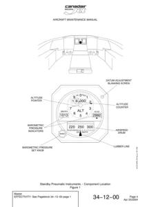
Reviews

There are no reviews yet.

Be the first to review “Airbus A318 A319 A320 A321 – Chapter 29 Hydraulic Power Maintenance Manual Rev 40 (2012) PDF”

What Our Customers Say

★★★★★ Live reviews from customers
Loading customer reviews...
0
    0
    Your Cart
    Your cart is emptyReturn to Shop
    🛒
    Recently Purchased
    🕒 verified order