
Airbus A350-900 & A350-1000 Aircraft Characteristics Airport and Maintenance Planning Manual AC Oct 2017
Original price was: $39.95.$24.95Current price is: $24.95.
Airbus A350 Aircraft Characteristics – Airport and Maintenance Planning (AC) manual, Revision No. 3 dated Oct 01/17, covering A350-900 and A350-1000 airport planning, ground handling, ground clearances, pavement data and rescue/fire fighting reference data.
Description
Airbus A350 Aircraft Characteristics – Airport and Maintenance Planning (AC) Manual
This is the Airbus A350 Aircraft Characteristics – Airport and Maintenance Planning (AC) manual, Revision No. 3, dated Oct 01/17. It is the airport and maintenance planning reference for the A350 XWB family, issued to give airport operators, airlines and Maintenance/Repair Organizations (MRO) the data they need for airport and maintenance facilities planning. The Airbus A350-900 and A350-1000 Aircraft Characteristics Airport and Maintenance Planning Manual AC Oct 2017 covers the A350-900 and A350-1000 series aircraft, both powered by Rolls-Royce Trent XWB engines (Trent XWB-84 and Trent XWB-97).
The manual is organised into numbered chapters that build from basic aircraft description through to pavement ratings and rescue/fire fighting reference charts. Everything below is drawn from the manual’s own contents listing and subject structure.
File Details
- Manual type: Aircraft Characteristics – Airport and Maintenance Planning (AC)
- Brand / manufacturer: Airbus
- Models covered: A350-900, A350-1000
- Engines referenced: Rolls-Royce Trent XWB-84, Trent XWB-97
- Language: English
- File format: PDF
- Document revision: Revision No. 3
- Revision date: Oct 01/17
Chapters Covered
The Airbus A350-900 A350-1000 Aircraft Characteristics Airport and Maintenance Planning Manual AC Oct 2017 is arranged into the following chapters and main subject areas:
- Chapter 1 – Introduction, Glossary
- Chapter 2 – Aircraft Description: General Aircraft Characteristics Data, General Aircraft Dimensions, Ground Clearances, Interior Arrangements – Plan View, Interior Arrangements – Cross Section, Cargo Compartments, Door Clearances and Location, Escape Slides, Landing Gear, Landing Gear Maintenance Pits, Exterior Lighting, Antennas and Probes Location, Engine and Nacelle, Auxiliary Power Unit, Leveling/Symmetry and Alignment, Jacking for Maintenance, Jacking of the Landing Gear
- Chapter 3 – Aircraft Performance: General Information, Payload/Range – ISA Conditions, Take-Off Weight Limitation, Landing Field Length, Final Approach Speed
- Chapter 4 – Ground Maneuvering: Turning Radii, Minimum Turning Radii, Visibility from Cockpit in Static Position, Runway and Taxiway Turn Paths (90 deg and 135 deg turns, 180 deg turn on a runway, taxiway to taxiway turns), Runway Holding Bay, Minimum Line-Up Distance Corrections, Aircraft Mooring
- Chapter 5 – Terminal Servicing: Aircraft Servicing Arrangements, Typical Ramp Layout (Open Apron and Gate), Terminal Operations Full Servicing and Transit Turn Round Time, Ground Service Connections Layout, Grounding (Earthing) Points, Hydraulic Servicing, Electrical Servicing, Oxygen Servicing, Fuel Servicing, Pneumatic Servicing, Engine Oil Servicing, Potable Water Servicing, Waste Water Servicing, Cargo Control Panels, Engine Starting Pneumatic Requirements, Ground Pneumatic Power Requirements, Preconditioned Airflow Requirements, Ground Towing Requirements, De-Icing and External Cleaning
- Chapter 6 – Operating Conditions: Engine Exhaust Velocities and Temperatures (Ground Idle, Breakaway Power, Max Take-Off Power), Danger Areas of the Engines, APU Exhaust Velocities and Temperatures
- Chapter 7 – Pavement Data: Landing Gear Footprint, Maximum Pavement Loads, Landing Gear Loading on Pavement, Flexible Pavement Requirements (US Army Corps of Engineers Design Method), Flexible Pavement Requirements LCN Conversion, Rigid Pavement Requirements (Portland Cement Association Design Method), Rigid Pavement Requirements LCN Conversion, ACN/PCN Reporting System – Flexible and Rigid Pavements
- Chapter 8 – Scaled Drawings
- Chapter 10 – Aircraft Rescue and Fire Fighting: hazardous materials and components, crew rest compartment locations, wheel/brake overheat data, composite materials location, ground lock safety devices, emergency evacuation devices, passenger/crew doors and emergency exits, cockpit emergency exit, lower deck cargo doors, control panels, APU compartment access, aircraft ground clearances, structural break-in points, battery locations and access
As a whole, this document gives a technician, planner or ground engineer a single reference for how the A350-900 and A350-1000 sit on the ground, move on the ground, are serviced, and load the pavement beneath them. It combines physical geometry (dimensions, clearances, jacking points, turning radii) with operating data (turn round times, servicing connections, pneumatic and airflow requirements) and pavement engineering data (footprint, maximum pavement loads, flexible and rigid pavement requirements and ACN/PCN tables).
What This Airbus A350 Airport Planning Manual Gives You
Because it is written for airport and maintenance planning rather than line maintenance alone, this manual supports a wide set of planning and engineering tasks across both A350 variants:
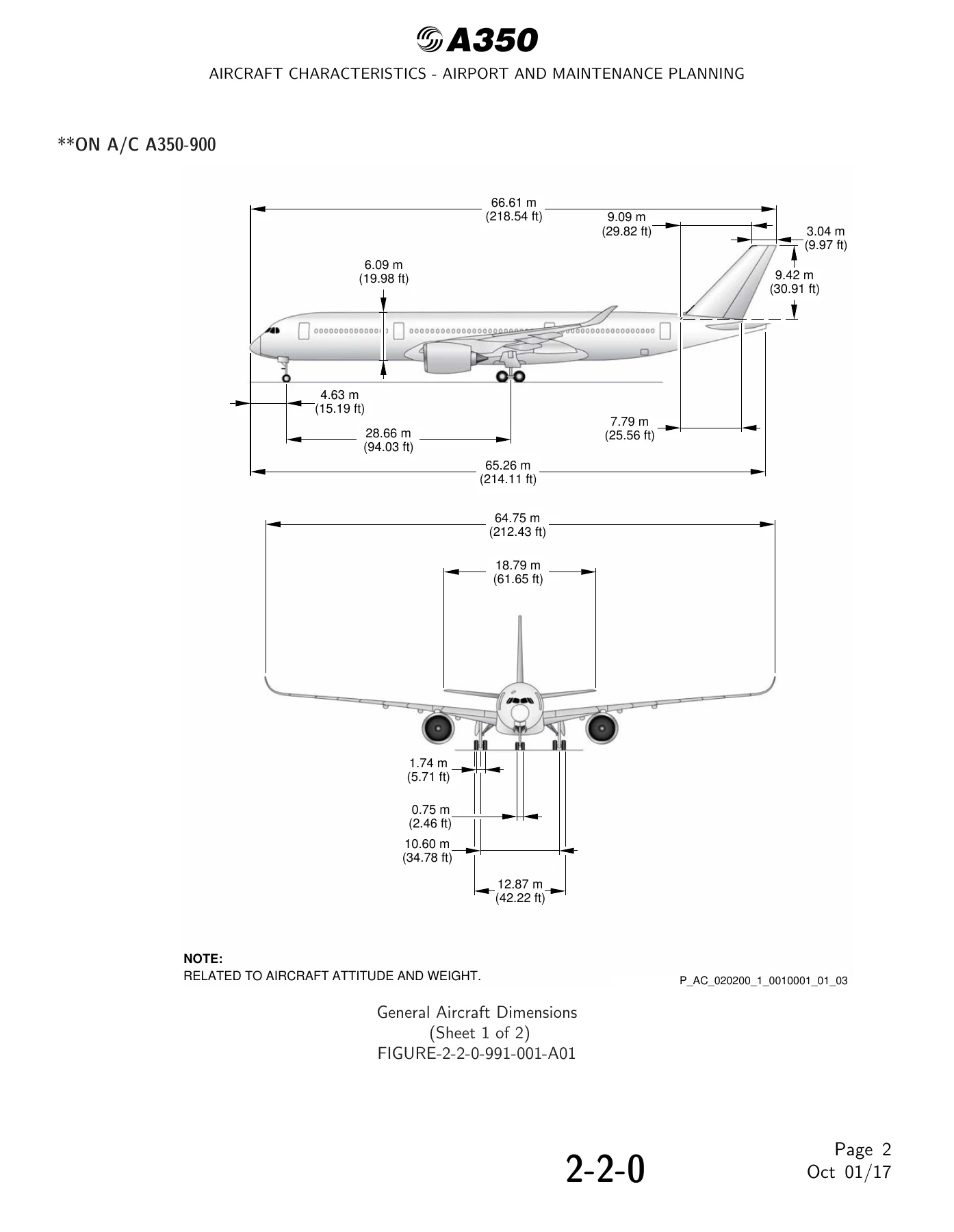
- Aircraft dimensions and geometry: General aircraft dimensions for both A350-900 and A350-1000, including length, wingspan, height and tailplane dimensions, with attitude and weight notes.
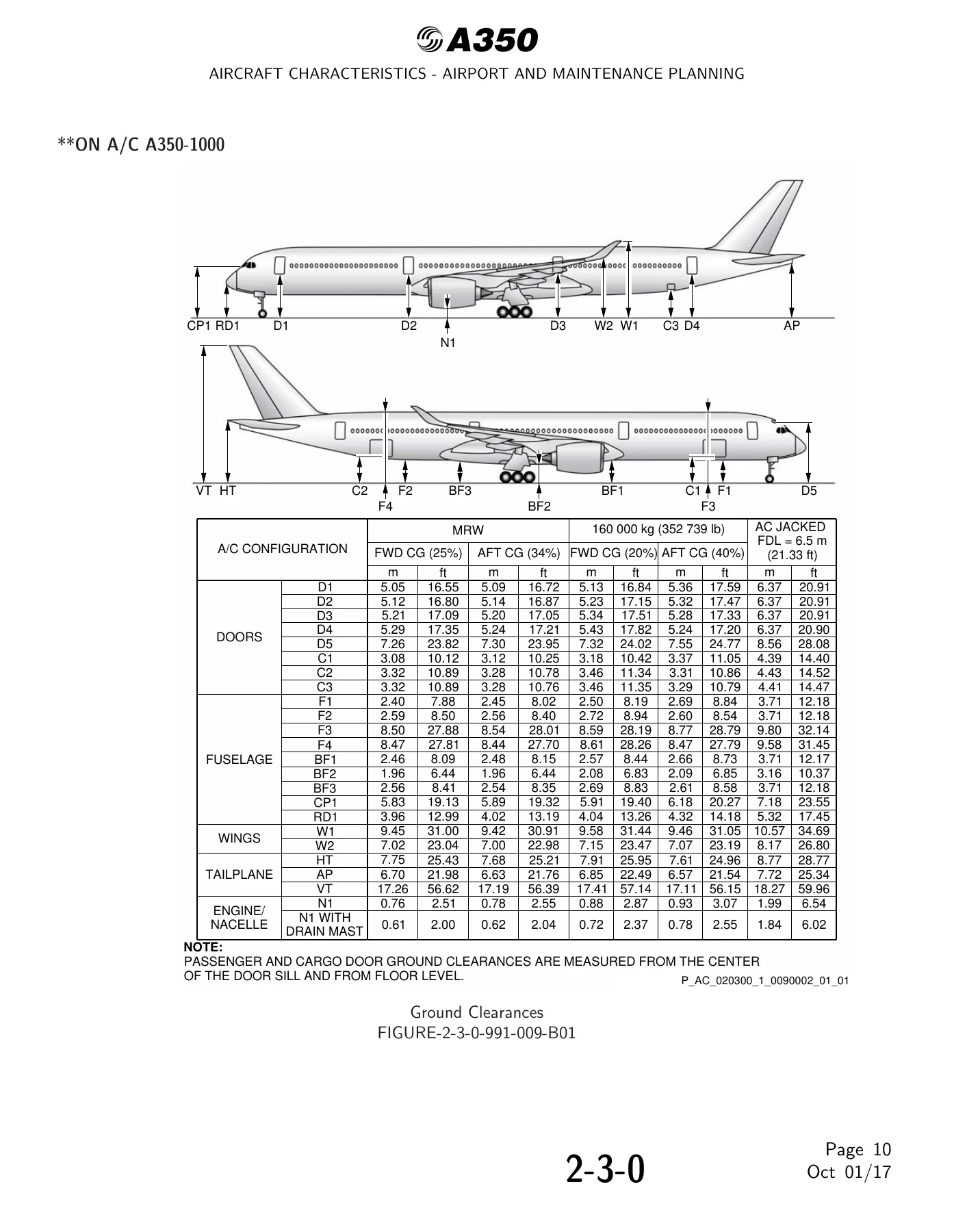
- Ground clearances: Heights of doors, fuselage, wings, tailplane and engine/nacelle items above ground for MRW, lighter maintenance weights, and aircraft on jacks with FDL at 6.50 m (21.33 ft).
- Door and cargo data: Door identification and location for passenger/crew doors, cockpit escape hatch, forward and aft cargo doors and bulk cargo door, plus door clearances and swing envelopes.
- Interior arrangements: Plan view and cross-section data for cabin layouts including seating abreast and aisle dimensions.
- Cargo compartments: Lower deck forward, aft and bulk cargo compartment locations, dimensions and standard load combinations (LD3 containers and 96 in x 125 in pallets).
- Landing gear: Main and nose landing gear descriptions for both variants (four-wheel twin-tandem bogie on the -900 and six-wheel triple-tandem bogie on the -1000), landing gear doors, maintenance pits, jacking data and jacking of the landing gear.
- Ground maneuvering: Turning radii tables and diagrams, minimum turning radii, visibility from the cockpit in static position, 90 deg / 135 deg / 180 deg turn paths and minimum line-up distance corrections.
- Terminal servicing: Ramp layouts for open apron and gate, full servicing and transit turn round time charts, ground service connection layout, grounding points, hydraulic, electrical, oxygen, fuel, pneumatic, oil, potable water and waste water servicing, cargo control panels.
- Ground support requirements: Engine starting pneumatic requirements, ground pneumatic power requirements, preconditioned airflow requirements and ground towing requirements with towbar design guidance.
- Operating conditions: Engine exhaust velocity and temperature contours for ground idle, breakaway power and max take-off power, danger areas of the engines, and APU exhaust velocity and temperature data.
- Pavement engineering: Landing gear footprint, maximum pavement loads, landing gear loading on pavement, flexible and rigid pavement requirements and ACN/PCN reporting tables for the operational weight variants.
- Rescue and fire fighting: Hazardous materials and components, wheel/brake overheat safety areas and recommendations, composite materials location, ground lock safety devices, emergency evacuation devices, door and exit operation and structural break-in points.
Why This Manual Matters
Airport and maintenance planning decisions depend on accurate, model-specific figures. Using generic or out-of-date dimensions risks jet blast damage, pavement overload, incorrect stand marking, or unsafe jacking and towing. This Airbus A350-900 A350-1000 Aircraft Characteristics Airport and Maintenance Planning Manual AC Oct 2017 provides the actual dimensional, clearance, servicing and pavement values for the A350-900 and A350-1000, including the weight-variant-specific data used for ACN/PCN calculations. For airport engineers, MRO planners and airline technical services, it is the reference that keeps facilities and procedures aligned with the aircraft they will actually handle.
IMAGES PREVIEW
Instant PDF Delivery
The Airbus A350 Aircraft Characteristics Airport and Maintenance Planning (AC) manual is delivered as an instant-download PDF. There is no shipping and no waiting. Once payment is complete you can open it on a computer, tablet or phone, search through it on screen, and print the pages you need for the hangar, the planning office or the apron. Whether you are preparing a stand layout, checking a towing limitation, comparing flexible and rigid pavement thickness or briefing a rescue and fire fighting team, this Airbus A350 airport planning manual puts the A350-900 and A350-1000 data at hand in one document.

Reviews
There are no reviews yet.