

Beechcraft Super 18 E18S E18S-9700 G18S H18 Parts Catalog (414-180154C)
Original price was: $39.95.$24.95Current price is: $24.95.
Comprehensive factory illustrated parts catalog for the Beechcraft Super 18 series, including models E18S, E18S-9700, G18S, and H18. Features complete assembly breakdowns, exploded view diagrams, official part numbers, and serial effectivity coding across 630 pages.
Description
Comprehensive Beechcraft Super 18 Parts Identification Resource
The Beechcraft Super 18 E18S E18S-9700 G18S H18 Parts Catalog (414-180154C) is the definitive illustrated parts reference for aircraft owners, FAA certified A&P mechanics, vintage aircraft restorers, and aviation maintenance facilities. Published by Parts and Service Operations at Beech Aircraft Corporation, this reissue catalog delivers comprehensive structural, mechanical, powerplant, and system breakdowns for the classic twin-engine Beechcraft Super 18 fleet. Every airframe assembly is thoroughly illustrated with detailed exploded diagrams down to individual detail components, washers, brackets, cotter pins, and attaching hardware.
File Details
- Manual Type: Illustrated Parts Catalog (IPC)
- Brand: Beechcraft (Beech Aircraft Corporation, Wichita, Kansas)
- Model Series: Beechcraft Super 18 Twin Engine Transport
- Applicable Models: E18S, E18S-9700, G18S, and H18
- Powerplant Compatibility: Pratt & Whitney Wasp Jr. R-985 Series Radial Engines
- Document Number: 414-180154C
- Publication Date / Status: Reissue August 21, 1962 (Reissue Code C)
- Language: English
- Page Count: 630 pages
- File Format: PDF Download
Document Organization & Chapters Covered
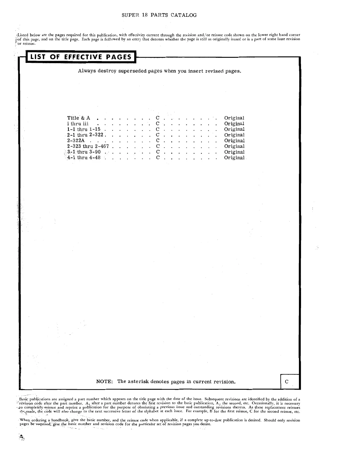
This factory parts catalog is divided into four distinct operational sections structured to make locating, cross-referencing, and procuring replacement aircraft hardware completely straightforward:
IMAGES PREVIEW
- Section 1 — Alphabetical Index: Complete alphabetic listing of aircraft assemblies, sub-assemblies, and installation names, referencing corresponding figure numbers across all systems (Figures 1 through 143).
- Section 2 — Illustrated Parts List: The primary catalog section breaking down the aircraft into assemblies, sub-assemblies, detail parts, and attaching hardware via an intuitive 7-column indenture system. Key figure coverage includes:
- Skin Diagrams: Outboard Wing (Figure 1), Fuselage Top and Bottom (Figure 2), Fuselage Sides (Figure 3), and Tail Group (Figure 4)
- Miscellaneous Tools and Equipment Installations (Figure 5)
- Fuselage Structure, Nose Cone, Radio Access, and Inspection Doors (Figure 6)
- Picture Window Installations and Curtain Hardware (Figure 7)
- Forward Radio Shelf & Fuel Gage Transmitter Cover (Figure 8)
- Nose Baggage Door, Locking Shafts, and Position Warning Switches (Figure 9)
- Cabin Airstair Door, Retraction Steps, Handle Linkages, and Secondary Latches (Figure 10)
- Emergency Exit Hatch, Internal Release Mechanisms, and Cam Locks (Figure 11)
- Fuselage Cockpit Section, Windshields, Glare Shields, and Storm Windows for E18S/E18S-9700 (Figure 12)
- Fuselage Cockpit Section, Triangular Side Windows, and Glazing for G18S and After (Figure 13)
- Pilot and Copilot Chair Assemblies, Leg Braces, and Height Adjusters (Figures 14 & 15)
- Pilot Compartment Floorboards, Pedal Plates, and Edging (Figure 16)
- Pilot and Lavatory Relief Tube Installations and Venturis (Figure 17)
- Cabin Furnishings, Glare Shields, Fire Extinguishers, and First Aid Kits (Figure 18)
- Cabin Center Floorboard Sections (Figure 19)
- Standard Upholstery, Rudder Tab Controls, Overhead Panels, and Indicator Dials (Figure 20)
- Lavatory Compartment, Chemical Toilet Shell, Lid, and Venting (Figure 21)
- Bulkhead No. 5 Sliding Doors and Bulkhead No. 9 Partitions (Figure 22)
- Baggage Compartment Liners, Shelves, and Webbing (Figure 23)
- Center Section Wing, Battery Boxes, Fuel Doors, and Oil Radiator Air Ducts (Figure 24)
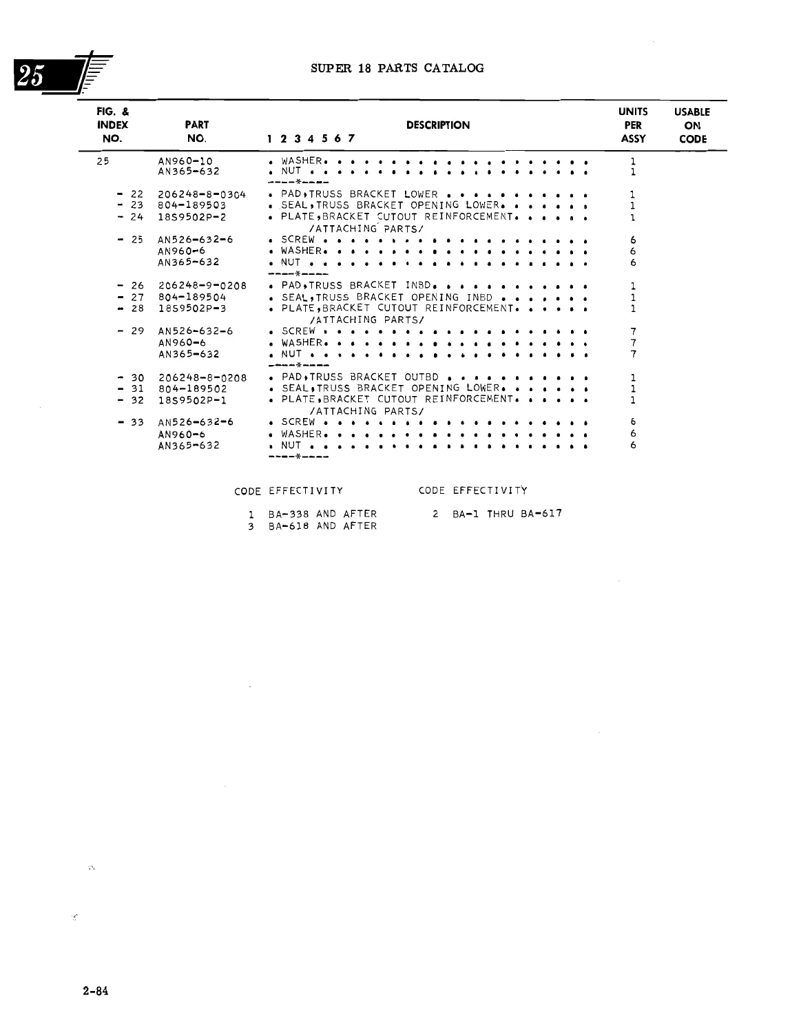
- Firewall Supports, Truss Connectors, and Seals (Figure 25)
- Firewall Assembly, Control Clamps, and Feedthrough Flanges (Figure 26)
- Landing Gear Doors and Operating Linkage Mechanisms (Figure 27)
- Outboard Wing Installations and Center Section Attach Hinges (Figure 28)
- Left Hand Outboard Wing Structure, Auxiliary Fuel Cells, and Access Covers (Figure 29)
- Right Hand Outboard Wing Structure, Heater Access, and Fuel Cells (Figure 30)
- Covered Aileron Assemblies, Tab Drives, and Counterbalance Weights (Figure 31)
- Aileron Structural Rib Frames LH & RH (Figures 32 & 33)
- Wing Flap Mechanisms, Structure, Fabric Covering, and Metal Skins (Figure 34)
- Tail Group Empennage, Stabilizer Fairings, and Static Wicks (Figure 35)
- Horizontal Stabilizer Structure & Elevator Tab Torque Drives (Figure 36)
- Vertical Fin Structure, Abrasion Shoes, and Rudder Hinges (Figure 37)
- Rudder Assembly, Horns, Actuating Rods, and Cloth Covering (Figure 38)
- Rudder Internal Skeletal Rib and Spar Framework (Figure 39)
- Elevator Assembly, Tab Actuators, and Balance Weights (Figure 40)
- Elevator Structural Framework, Ribs, and Spars (Figure 41)
- Flight Control Cabling, Torque Shafts, Pulleys, and Fairleads (Figure 42)
- Hydraulic Brake Lines, Master Cylinders, and Shuttle Valves (Figures 56–60)
- Main Landing Gear Shock Struts, Retract Motor, and Emergency Handcrank (Figures 61–64)
- Tail Wheel Retraction Truss, Locking Cables, and Shock Absorber (Figures 65–66)
- Janitrol Cabin Heating Systems, Solenoids, Ducts, and Thermostats (Figures 67–68)
- Powerplant Mounts, Radial Engine Baffles, Exhaust Muffs, and Collector Rings (Figures 74–85)
- Fuel System Plumbing, Selector Valves, Crossfeed Lines, and Boost Pumps (Figures 93–98)
- Oil Radiators, Bypass Valves, Tanks, and Dilution Controls (Figures 100–102)
- Hamilton Standard and Hartzell Propeller Installations and Governors (Figures 103–105)
- Instrument Flight Panels, Vacuum Lines, and Gyrosyn Compass Systems (Figures 107–114)
- Oxygen Cylinders, Regulators, Distribution Lines, and Masks (Figures 115–117)
- Electrical Regulators, Relays, Junction Boxes, and External Lights (Figures 118–121, 134–137)
- Autopilot Installations: Sperry, Lear L-2, and Honeywell H-14 (Figures 49–51)
- Section 3 — Alpha-Numerical Index: Exhaustive cross-reference listing of every Beechcraft part number, AN standard hardware code, and vendor component number referenced in Section 2, showing exactly which figure and index numbers apply.
- Section 4 — Spare Assembly Components: Complete parts breakdowns of factory spare sub-assemblies, ensuring you know exactly which individual components, bushings, or retainers are supplied when ordering assemblies.
As a whole, this manual gives aircraft mechanics and restoration specialists the foundational technical transparency needed to order the correct Beechcraft factory parts, verify original equipment specifications, track airframe modifications, and assemble components in precise factory-approved sequences.
Airframe, Structure & Serial Effectivity Rigor
A critical challenge when servicing the Beechcraft Super 18 series is navigating continuous production improvements across production years. The Beechcraft Super 18 E18S E18S-9700 G18S H18 Parts Catalog solves this by integrating extensive serial number effectivity codes across every parts breakdown table. Whether your aircraft is an early model E18S or E18S-9700 (serials BA-1 through BA-460), a mid-production G18S (such as BA-461 through BA-617), or a late-production H18 (serials BA-618, BA-632 and after), this catalog pinpoints exact configuration variations:
- Cockpit Enclosures & Glazing: Details the specific cockpit window framing, sliding storm windows, and windshield upper/lower cap extrusions across early multi-pane configurations versus late-style large storm windows and one-piece side glazing.
- Flight Control Surfaces: Distinguishes between fabric-covered flaps and factory metal-covered flap conversions (superseding 414-160010 series), including nose rib profiles, trailing edges, and skin doubler plates.
- Fuel Subsystems: Illustrates both standard center section wing fuel cell arrangements and auxiliary outboard wing fuel cell installations (such as kit 414-110000 series), along with nose fuel tank doors, submerged booster pumps, and liquidometer transmitter installations.
- Cabin Furnishings: Covers factory interior seat configurations from Beech standard reclining seats to Hardman pilot chairs, passenger bulkhead dividers (No. 5 and No. 9), lavatory chemical toilet setups, and aft baggage compartment liners.
Complete Attaching Hardware Breakdowns
Reassembling airframe components requires strictly adhering to factory fastener specs. Every assembly in the Beechcraft Super 18 Parts Catalog features an explicit /ATTACHING PARTS/ section isolated with standard dashed formatting (----*----). This provides the exact part numbers, standard military specifications (AN, NAS, MS), quantities, and thread dimensions for all mounting bolts, clevis pins, washers, elastic stop nuts, and sheet metal screws required to mount wings, landing gear doors, empennage surfaces, and engine firewall mounts.
Why This Manual Is Essential For Your Super 18
Keeping twin-engine Beechcraft aircraft airworthy demands precision. Using incorrect hardware or superseded components can result in improper rigging, premature wear, or airworthiness compliance issues. This parts catalog gives you the confidence of knowing the exact original manufacturer specification for every nut, bolt, skin panel, and hydraulic line on your aircraft.
Delivered as an instant PDF download, this digital catalog eliminates shipping delays and puts over 600 pages of factory parts documentation on your workstation, tablet, or smartphone immediately. You can search part numbers across the alpha-numerical index, zoom in on high-resolution exploded views right at the hangar bench, or print individual chapters and schematics for specific maintenance tasks.

Reviews
There are no reviews yet.