★ TRUSTED BY 321,897+ PROFESSIONALS WORLDWIDE
🏢
Trusted Business
Verified & Licensed
🛡️
Virus Free Files
100% Safe Downloads
🔒
Secure Payment
SSL Protected
Instant Delivery
Available Immediately
Sale!

Continental IO-360 Series Aircraft Engines Maintenance and Overhaul Manual – M-7 (September 2016) – PDF Download

Original price was: $39.95.Current price is: $25.95.

Complete factory maintenance and overhaul manual for Continental IO-360 series aircraft engines. Covers all models including IO-360-A, AB, AF, C, CB, D, DB, ES, G, GB, H, HB, J, JB, K, and KB. Includes detailed specifications, inspection schedules, troubleshooting, and overhaul procedures. The official FAA-accepted Instructions for Continued Airworthiness (ICA) for these engines.

Instant PDF Download
Available immediately
💾
Save to Your Device
Download & keep forever
🛡️
Antivirus Scanned
100% virus-free
🌍
Trusted Worldwide
175,000+ customers

Description

Continental IO-360 Series Aircraft Engines Maintenance and Overhaul Manual – M-7 (September 2016) – PDF Download

This is the complete factory-authorized Maintenance and Overhaul Manual for Continental Motors IO-360 series aircraft engines. Officially designated as Publication Number M-7, this manual serves as the primary Instructions for Continued Airworthiness (ICA) for the entire IO-360 engine family. It is the essential technical reference for aircraft mechanics, maintenance facilities, and overhaul shops working on these popular, reliable six-cylinder powerplants.

This comprehensive document contains all the procedures, specifications, and technical data required to properly maintain, troubleshoot, and overhaul the Continental IO-360 series engines. It covers the engine from nose to tail, providing detailed instructions for everything from routine 50-hour inspections to a complete engine teardown and rebuild. The manual is the definitive source for engine specifications, torque values, overhaul limits, and approved maintenance practices as defined by the FAA.

File Details

  • Manual Type: Factory Maintenance and Overhaul Manual
  • Document Number: M-7
  • Publication Date: 3 September 2016
  • Models Covered: Continental IO-360-A, AB, AF, C, CB, D, DB, ES, G, GB, H, HB, J, JB, K, KB
  • Language: English
  • Page Count: 660 Pages
  • File Format: High-Quality PDF (Searchable)

IMAGES PREVIEW

Continental IO-360 Series Aircraft Engines Maintenance and Overhaul Manual - M-7 (September 2016) - PDF Download — PDF page 1 preview
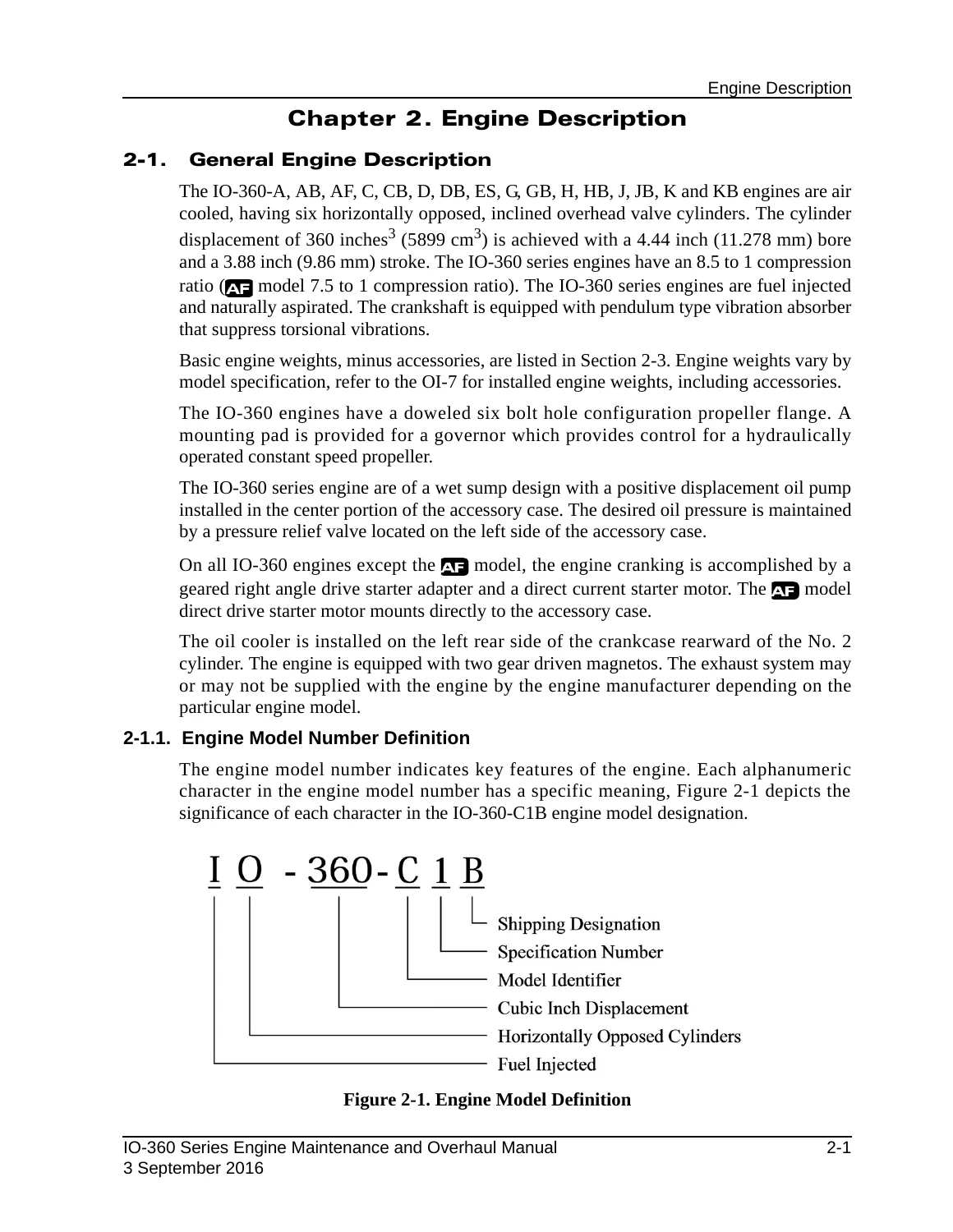
Continental IO-360 Series Aircraft Engines Maintenance and Overhaul Manual - M-7 (September 2016) - PDF Download — PDF page 45 preview
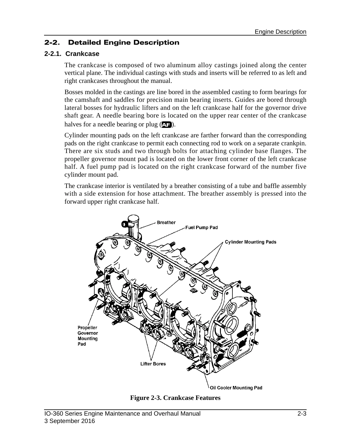
Continental IO-360 Series Aircraft Engines Maintenance and Overhaul Manual - M-7 (September 2016) - PDF Download — PDF page 47 preview

Chapters Covered

  • Chapter 1. Introduction – Scope, effectivity, safety advisories, compliance, order of precedence, publication access, and contact information.
  • Chapter 2. Engine Description – General engine description, model number definition, cylinder numbering, detailed descriptions of all major systems: crankcase, drive train (crankshaft, connecting rods, camshaft), cylinders, lubrication, fuel, ignition, cooling, induction, exhaust, and complete engine specifications and performance data for every model.
  • Chapter 3. Special Tools and Supplies – Required special tools, vendor contact information, mechanic’s tools, and authorized lubricants, sealants, and adhesives.
  • Chapter 4. Airworthiness Limitations – Mandatory replacement times, inspection intervals, and distribution of changes to airworthiness limitations.
  • Chapter 5. Engine Removal and Installation – Detailed procedures for engine removal, handling, acceptance inspection, installation, pre-oiling, fuel system purge, and post-installation checks. Includes dimensional engine installation drawings.
  • Chapter 6. Engine Inspection and Service – Comprehensive inspection program including 25-hour, 50-hour, 100-hour, and 500-hour inspections. Detailed service procedures for oil changes, filter replacement, oil sample collection, ignition system maintenance, and cylinder inspections (visual, differential pressure, borescope).
  • Chapter 7. Engine Operation – Normal operation procedures including cold start, hot start, flooded engine start, ground run-up, shutdown, and emergency procedures (engine fire, roughness, high cylinder head or oil temperature, low oil pressure, overspeed).
  • Chapter 8. Troubleshooting – In-depth fault isolation charts for all major systems: engine won’t start, runs rough, performance issues, induction, fuel injection, charging, starting, ignition, lubrication, and cylinder problems.
  • Chapter 9. Engine Preservation and Storage – Instructions for temporary and indefinite storage, including preservation procedures and checklists.
  • Chapter 10. Non-Overhaul Repair and Replacement – Part replacement references and detailed maintenance procedures for fuel pumps, injectors, starter motors, alternators, magnetos, lubrication system components, cylinders, and the crankshaft nose oil seal.
  • Chapter 11. Engine Overhaul Introduction – Overhaul schedule, sequence, and comprehensive overhaul checklists.
  • Chapter 12. Engine Disassembly – Step-by-step engine disassembly instructions for all major components including ignition, fuel, induction, alternator, starter, accessory case, oil pump, sump, baffles, cylinders, and pistons.
  • Chapter 13. Component Disassembly – Detailed disassembly procedures for ignition, fuel injection, starter, cylinders, crankcase, and drive train components.
  • Chapter 14. Engine Cleaning – Approved methods for cleaning engine parts.
  • Chapter 15. Overhaul Inspection and Repair – Visual, fluorescent penetrant, magnetic particle, and ultrasonic inspection procedures. Covers dimensional inspection, repair, and overhaul of all major components including crankcase, drive train, cylinders, starter, and lubrication system. Includes repair instructions for valve seats, guides, and rocker arms.
  • Chapter 16. Component Assembly – Assembly instructions for fuel injection system, alternator, starter adapter, exhaust system, engine cylinder, oil pump, crankcase, and drive train.
  • Chapter 17. Engine Assembly – Complete engine assembly sequence including lubrication, crankcase assembly, cylinder installation, torque procedures, oil sump installation, accessory case installation, and final installation of all systems.
  • Chapter 18. Post-Overhaul Test and Adjustments – Standard acceptance test and oil consumption test requirements and procedures.
  • Appendix A. Definitions – Glossary of common terms and acronyms.
  • Appendix B. Torque Specifications – Complete fastener torque chart for the entire engine.
  • Appendix C. Standard Practices – Handling parts, replacement parts, safety wiring, tab washer installation, Heli-coil replacement, stud replacement, cotter pin installation, fuel system service, gasket maker application, and hose/tubing installation.
  • Appendix D. Overhaul Dimensional Limits – Complete overhaul dimension tables for fuel injection, starter, ignition, lubrication, cylinders, crankcase, crankshaft, connecting rods, bearings, camshaft, and stud height settings.

Complete PDF Bookmark Tree

Complete Bookmarks

The complete bookmarks in the “Continental IO-360 Series Aircraft Engines Maintenance and Overhaul Manual – M-7 (September 2016) – PDF Download” are as follows:

Chapter 1 . Introductionp. 29
1-1. Scope and Purpose of This Manualp. 29
1-1.1. Instructions for Continued Airworthinessp. 29
1-1.2. Effectivity Symbolsp. 30
1-1.3. Advisoriesp. 31
1-1.4. Using this Manualp. 31
Figure 1-1. Figure and Index Referencep. 32
1-1.5. Compliancep. 33
1-1.6. Order of Precedencep. 34
1-2. Publicationsp. 34
1-2.1. Publication Accessp. 34
1-2.2. Publication Changesp. 34
1-2.2.1. Update/Change Distributionp. 35
Figure 1-2. Change Page Identificationp. 36
Figure 1-3. List of Effective Pagesp. 37
1-2.3. Service Documentsp. 38
1-2.3.1. Service Documents Incorporated in this Manualp. 39
1-2.3.2. Service Documents Released After Publicationp. 41
1-2.4. Related Publicationsp. 42
Table 1-1. Related Publicationsp. 42
1-2.4.1. Suggestions and Correctionsp. 42
1-3. Contact Informationp. 43
Chapter 2 . Engine Descriptionp. 45
2-1. General Engine Descriptionp. 45
2-1.1. Engine Model Number Definitionp. 45
Figure 2-1. Engine Model Definitionp. 45
2-1.2. Cylinder Number Designationsp. 46
Figure 2-2. Cylinder Number Designationp. 46
2-2. Detailed Engine Descriptionp. 47
2-2.1. Crankcasep. 47
Figure 2-3. Crankcase Featuresp. 47
2-2.2. Engine Drive Trainp. 48
Figure 2-4. Drive Train (Except AF)p. 48
2-2.2.1. Crankshaftp. 49
Figure 2-5. Crankshaftp. 49
2-2.2.2. Connecting Rodsp. 50
Figure 2-6. Connecting Rodp. 50
2-2.2.3. Camshaftp. 51
Figure 2-7. Camshaftp. 51
2-2.3. Cylindersp. 52
Figure 2-8. Crossflow Cylinder Featuresp. 52
2-2.3.1. Pistonsp. 53
Figure 2-9. Piston Featuresp. 53
2-2.3.2. Hydraulic Valve Liftersp. 53
2-2.4. Lubrication Systemp. 54
Figure 2-10. Lubrication Schematicp. 55
2-2.4.1. Oil Pumpp. 56
Figure 2-11. Oil Pumpp. 56
2-2.4.2. Oil Sumpsp. 57
2-2.4.3. Oil Cooler and Oil Temperature Control Valvep. 57
Figure 2-12. Oil Coolerp. 57
2-2.5. Fuel Systemp. 58
Figure 2-13. IO-360 Fuel System Schematic (Except D34, DB34 and ES)p. 59
Figure 2-14. IO-360 Air Throttle and Metering Unitp. 60
Figure 2-15. IO-360 Fuel System Schematic (D34, DB34 and ES Models)p. 60
2-2.5.1. Fuel Pumpp. 61
Table 2-1. Standard Fuel Pump Featuresp. 61
Figure 2-16. IO-360 Standard Fuel Pump (All Models Except D34, DB34 and ES)p. 61
Table 2-2. Aneroid Fuel Pump Featuresp. 62
Figure 2-17. IO-360 Aneroid Fuel Pump (D34, DB34 and ES Models)p. 62
2-2.5.2. Fuel Injectorsp. 62
Figure 2-18. IO-360 Fuel Injector Nozzlep. 63
2-2.6. Starter Assemblyp. 64
Figure 2-19. Starting System (Except AF)p. 64
2-2.7. Alternatorp. 65
2-2.8. Ignition Systemp. 65
Figure 2-20. Continental Motors Magneto Part Number Definitionp. 66
Figure 2-21. CM Ignition System Schematicp. 66
Figure 2-22. Champion (Slick) Ignition System Schematicp. 67
2-2.9. Engine Coolingp. 67
Figure 2-23. Engine Coolingp. 67
2-2.10. Induction Systemp. 68
Figure 2-24. Induction System (Except AF and ES)p. 68
Figure 2-25. Induction System (AF and ES Models)p. 69
2-2.11. Exhaust Systemp. 69
2-3. Engine Specificationsp. 69
2-3.1. IO-360-A, AB Specificationsp. 70
Table 2-3. IO-360-A, AB Specificationsp. 70
2-3.2. IO-360-AF Specificationsp. 72
Table 2-4. IO-360-AF Specificationsp. 72
2-3.3. IO-360-C, CB, G, GB, H, HB Specificationsp. 74
Table 2-5. IO-360-C, CB, G, GB, H, HB Specificationsp. 74
2-3.4. IO-360-D,DB Specificationsp. 76
Table 2-6. IO-360-D, DB Specificationsp. 76
2-3.5. IO-360-J, JB, K Specificationsp. 78
Table 2-7. IO-360-J, JB, K Specificationsp. 78
2-3.6. IO-360-KB Specificationsp. 80
Table 2-8. IO-360-KB Specificationsp. 80
2-3.7. IO-360-ES Specificationsp. 82
Table 2-9. IO-360-ES Specificationsp. 82
2-3.8. IO-360-Accessory Drive Ratiosp. 84
Table 2-10. IO-360-A, AB Accessory Drive Ratiosp. 84
Table 2-11. IO-360-AF Accessory Drive Ratiosp. 84
Table 2-12. IO-360-ES Accessory Drive Ratiosp. 85
Table 2-13. IO-360-C, CB, G, GB Accessory Drive Ratiosp. 85
Table 2-14. IO-360-D, DB, H, HB, J, JB Accessory Drive Ratiosp. 86
Table 2-15. IO-360-K, KB Accessory Drive Ratiosp. 86
2-3.8.1. Accessory Drive Padp. 86
2-3.9. Oil Specificationsp. 86
2-3.10. Performance Datap. 87
2-3.10.1. IO-360-A, AB Performance Chartsp. 88
Figure 2-26. IO-360-A, AB Sea Level Performance Curvesp. 88
Figure 2-27. IO-360-A, AB Fuel Pressure vs. Sea Level Standard Brake Horsepowerp. 89
Figure 2-28. IO-360-A, AB Altitude Performancep. 90
2-3.10.2. IO-360-AF Performance Chartsp. 91
Figure 2-29. IO-360-AF Sea Level Performance Curvesp. 91
Figure 2-30. IO-360-AF Fuel Flow vs. Brake Horsepowerp. 92
Figure 2-31. IO-360-AF Altitude Performancep. 93
Figure 2-32. IO-360-AF Sea Level Performance – Full Richp. 94
2-3.10.3. IO-360-C, CB, D, DB, G, GB, H, HB Performance Chartsp. 95
Figure 2-33. IO-360-C, CB, D, DB, G, GB, H, HB Sea Level Performance Curvesp. 95
Figure 2-34. IO-360-C, CB, D, DB, G, GB, H, HB Fuel Flow vs. Sea Level Standard Brake Horsepowerp. 96
Figure 2-35. IO-360-C, CB, D, DB, G, GB, H, HB Altitude Performancep. 97
2-3.10.4. IO-360-J, JB Performance Chartsp. 98
Figure 2-36. IO-360-J, JB Sea Level Performance Curvesp. 98
Figure 2-37. IO-360-J, JB Fuel Flow vs. Sea Level Standard Brake Horsepowerp. 99
Figure 2-38. IO-360-J, JB Altitude Performancep. 100
2-3.10.5. IO-360-K, KB Performance Chartsp. 101
Figure 2-39. IO-360-K, KB Sea Level Performance Curvesp. 101
Figure 2-40. IO-360-K, KB Fuel Flow vs. Sea Level Standard Brake Horsepowerp. 102
Figure 2-41. IO-360-K, KB Altitude Performancep. 103
2-3.10.6. IO-360 ES Performance Chartsp. 104
Figure 2-42. IO-360-ES Sea Level Performance Curvesp. 104
Figure 2-43. IO-360-ES Fuel Flow vs. Sea Level Standard Brake Horsepowerp. 105
Figure 2-44. IO-360-ES Altitude Performancep. 106
Figure 2-45. IO-360-ES Sea Level Performance – Full Richp. 107
Chapter 3 . Special Tools and Suppliesp. 109
3-1. Special Toolsp. 109
3-1.1. Vendor Contact Informationp. 109
3-1.2. Mechanic’s Toolsp. 109
3-2. Lubricants, Sealants and Adhesivesp. 109
Chapter 4 . Airworthiness Limitationsp. 111
4-1. Mandatory Replacement Timesp. 111
4-2. Mandatory Inspection Intervalsp. 111
4-3. Other Related Proceduresp. 111
4-4. Distribution of Changes to Airworthiness Limitationsp. 111
Chapter 5 . Engine Removal and Installationp. 113
5-1. Engine Removalp. 113
5-1.1. Tools and Consumable Supplies Requiredp. 113
5-1.2. Engine Removal Procedurep. 113
5-2. Engine Installationp. 116
5-2.1. Tools and Consumable Supplies Requiredp. 116
5-2.2. Engine Receipt and Handlingp. 117
5-2.3. Uncrating the Enginep. 117
5-2.4. Crating an Engine for Shippingp. 118
5-2.5. Acceptance Inspectionp. 118
5-2.6. Engine Transportp. 119
5-3. Installation Proceduresp. 120
5-3.1. Prepare Aircraft for Engine Installationp. 120
5-3.2. Prepare the Engine for Installationp. 120
5-3.3. Installation Sequencep. 122
5-3.4. Engine Pre-oilingp. 123
5-3.4.1. Pre-oiling Method 1p. 123
5-3.4.2. Pre-oiling Method 2p. 124
5-3.5. Fuel Injection System Purgep. 125
5-3.6. Installation Inspectionp. 126
5-3.7. Preflight and Run-upp. 126
5-4. Engine Installation Drawingsp. 127
5-4.1. IO-360 Common Installation Drawingsp. 127
Figure 5-1. Exhaust Port Dimensionsp. 127
Figure 5-2. Propeller Flange Dimensionsp. 128
Figure 5-3. 28V Gear Driven Alternator Detailp. 129
Figure 5-4. 15V Gear Driven Alternator Detailp. 129
Figure 5-5. 24V Belt Driven Alternator Detailp. 129
Figure 5-6. Installation Drawing 629385 (Top View) (1 of 3)p. 131
Figure 5-7. Installation Drawing 629385 (Rear View) (2 of 3)p. 133
Figure 5-8. Installation Drawing 629385 (Left Side View) (3 of 3)p. 135
Figure 5-9. Installation Drawing 631721 (Top View) (1 of 3)p. 137
Figure 5-10. Installation Drawing 631721 (Rear View) (2 of 3)p. 139
Figure 5-11. Installation Drawing 631721 (Left Side View) (3 of 3)p. 141
Figure 5-12. Installation Drawing 632619 (Top View) (1 of 3)p. 143
Figure 5-13. Installation Drawing 632619 (Rear View) (2 of 3)p. 145
Figure 5-14. Installation Drawing 632619 (Left Side View) (3 of 3)p. 147
Figure 5-15. Installation Drawing 656139 (Top View) (1 of 4)p. 149
Figure 5-16. Installation Drawing 656139 (Rear View) (2 of 4)p. 151
Figure 5-17. Installation Drawing 656139 (Left Side View) (3 of 4)p. 153
Figure 5-18. Installation Drawing 656139 (Front View) (4 of 4)p. 155
Figure 5-19. Installation Drawing 652898 (Top View) (1 of 4)p. 157
Figure 5-20. Installation Drawing 652898 (Rear View) (2 of 4)p. 159
Figure 5-21. Installation Drawing 652898 (Left Side View) (3 of 4)p. 161
Figure 5-22. Installation Drawing 652898 (Front View) (4 of 4)p. 163
Figure 5-23. Installation Drawing 658511 (Top View) (1 of 4)p. 165
Figure 5-24. Installation Drawing 658511 (Rear View) (2 of 4)p. 167
Figure 5-25. Installation Drawing 658511 (Left Side View) (3 of 4)p. 169
Figure 5-26. Installation Drawing 658511 (Front View) (4 of 4)p. 171
Chapter 6 . Engine Inspection and Servicep. 173
6-1. Inspection Program Introductionp. 173
6-2. Inspection and Maintenance Schedulep. 173
6-3. Scheduled Inspectionsp. 173
Table 6-1. Engine Inspection and Maintenance Schedulep. 174
6-3.1. One Time Post – Installation Inspectionsp. 175
6-3.2. 25-Hour Initial Operation Inspectionp. 175
6-3.3. 50-Hour Engine Inspectionp. 177
6-3.4. 100-Hour (Annual) Engine Inspectionp. 178
6-3.5. 500-Hour Engine Inspectionp. 179
6-3.6. Visual Inspectionp. 180
6-3.7. Engine Operational Checkp. 182
Table 6-2. Engine Operation Prerequisitesp. 182
6-3.7.1. Engine Operating Limitsp. 183
Table 6-3. IO-360 Engine Operating Limitsp. 183
6-3.7.2. Maintenance Preflight Inspectionp. 184
6-3.7.3. Oil Pump Operational Checkp. 186
6-3.7.4. Fuel System Operational Checkp. 186
6-3.7.4.1. Fuel System Operational Checkout with the Port-Test Unitp. 186
6-3.7.4.2. Fuel System Operational Checkout with Calibrated Gaugesp. 186
6-3.7.4.3. Fuel System Operational Checkout Procedurep. 186
6-3.7.5. Magneto RPM Drop Checkp. 187
6-3.7.6. Post Shutdown Inspectionp. 188
6-3.8. Engine Oil Servicingp. 189
6-3.8.1. Check and Replenish Engine Oil Levelp. 189
Figure 6-1. IO-360 Oil Servicing Pointsp. 190
Figure 6-2. IO-360-AF and ES Oil Servicing Pointsp. 191
6-3.8.2. Oil Changep. 192
Figure 6-3. Disposable Oil Filter and Integral Screenp. 193
6-3.8.3. Check for Oil Leaksp. 194
6-3.8.4. Oil Sample Collectionp. 194
6-3.8.5. Oil Trend Monitoring and Spectrographic Oil Analysisp. 194
6-3.9. Ignition System Maintenancep. 195
6-3.9.1. Magneto Timingp. 195
6-3.9.1.1. Crankshaft Top Dead Center Alignmentp. 195
6-3.9.1.2. Magneto to Engine Timingp. 195
6-3.9.2. Spark Plug Maintenancep. 195
6-3.9.3. Ignition Harness Maintenancep. 195
6-3.10. Engine Adjustmentsp. 196
6-3.10.1. Oil Pressure Adjustmentp. 196
6-3.10.2. Fuel System Adjustmentp. 196
6-3.10.3. Auto Leaning Schedule Adjustmentsp. 196
6-3.10.4. Belt Tension Check and Adjustmentp. 196
6-3.11. Cylinder Inspectionsp. 197
Table 6-4. Cylinder Inspection Tasks and Referencesp. 197
6-3.11.1. Cylinder Visual Inspectionsp. 197
6-3.11.2. Differential Pressure Testp. 197
6-3.11.2.1. Differential Pressure Tester E2M Setupp. 197
6-3.11.2.2. Differential Pressure Tester Reliability Checkp. 197
6-3.11.2.3. Leak Checkp. 197
6-3.11.2.4. Cylinder Differential Pressure Testp. 197
6-3.11.3. Cylinder Borescope Inspectionp. 198
6-3.11.4. Cylinder to Crankcase Mounting Deck Inspectionp. 198
6-3.11.5. Baffle Inspectionp. 198
6-3.11.6. Cowling Inspectionp. 198
6-3.12. Crankcase Inspectionp. 198
6-3.13. Engine Mount Inspectionp. 198
6-3.14. Induction System Inspectionp. 198
6-3.15. Ignition System Inspectionp. 198
6-3.15.1. Impulse Coupling Functional Checkp. 198
6-3.15.2. Magneto Drive Coupling Inspectionp. 199
6-3.16. Engine Gauge Inspectionp. 199
6-3.17. Fuel System Inspectionp. 199
6-3.18. Engine Control Linkage Inspectionp. 199
6-3.19. Induction or Cylinder Drain Inspectionp. 199
6-3.20. Alternator Inspectionp. 199
6-3.20.1. Alternator Drive Hub Inspectionp. 199
6-4. Unscheduled Maintenancep. 200
6-4.1. Propeller Strikep. 200
6-4.1.1. Propeller Strike Inspectionp. 200
6-4.2. Hydraulic Lock Inspectionp. 200
6-4.3. Engine Overspeed Inspectionsp. 200
6-4.3.1. Category I Overspeed Inspectionp. 200
6-4.3.2. Category II Overspeed Inspectionp. 200
6-4.3.3. Category III Overspeed Inspectionp. 200
6-4.4. Lightning Strike Inspectionp. 200
6-4.5. Contaminated Fuel System Inspectionp. 200
6-4.6. Foreign Object Contamination Inspectionp. 200
6-5. Inspection Checklistsp. 201
Table 6-5. Engine Operational Checklistp. 203
Table 6-6. 25-Hour Initial Operation Inspection Checklistp. 205
Table 6-7. 50-Hour Engine Inspection Checklistp. 207
Table 6-8. 100-Hour Engine Inspection Checklistp. 209
Table 6-9. 500-Hour Engine Inspection Checklistp. 211
Table 6-10. Cylinder Inspection Checklistp. 213
Chapter 7 . Engine Operationp. 215
7-1. Introductionp. 215
7-2. Flight Prerequisitesp. 215
7-2.1. Oil Change Intervalp. 215
7-2.2. Engine Fuel Requirementsp. 215
7-2.3. Flight Check and Break-Inp. 215
7-2.3.1. Engine Break-Inp. 215
7-2.3.2. Flight Checkp. 215
7-2.3.2.1. IO-360 Standard Fuel System Flight Check (except D34, DB34 and ES)p. 215
7-2.3.2.2. IO-360 Altitude Compensating Fuel System Flight Check (D34, DB34 and ES Models)p. 215
7-3. Normal Operationp. 216
7-3.1. Pre-operational Requirementsp. 216
7-3.2. Engine Startp. 216
7-3.2.1. Cold Startp. 217
7-3.2.2. Flooded Enginep. 217
7-3.2.3. Hot Startp. 217
7-3.3. Ground Run-upp. 218
7-3.4. Engine Shutdownp. 218
7-4. Emergency Operationp. 219
7-4.1. Engine Fire During Startp. 219
7-4.2. Engine Roughnessp. 219
7-4.3. High Cylinder Head Temperaturep. 219
7-4.4. High Oil Temperaturep. 220
7-4.5. Low Oil Pressurep. 220
7-4.6. Engine Overspeedp. 221
Table 7-1. Overspeed Categoriesp. 221
7-5. Engine Operation in Abnormal Environmentsp. 222
7-5.1. Engine Operation in Extreme Coldp. 222
7-5.1.1. Engine Preheatingp. 222
7-5.1.1.1. Engine Preheat with a Combustion Heaterp. 222
7-5.1.1.2. Engine Preheat with an Engine-Mounted Preheaterp. 222
7-5.1.1.3. Cold Weather Starting Without Preheatingp. 222
7-5.2. Engine Operation in Hot Weatherp. 222
7-5.2.1. Cooling an Engine in Hot Weatherp. 223
7-5.2.2. Engine Restart in Hot Weatherp. 223
7-5.2.3. Ground Operation at High Density Altitudep. 223
Chapter 8 . Troubleshootingp. 225
8-1. General Troubleshootingp. 226
Figure 8-1. Engine Will Not Startp. 226
8-1.1. Engine Runs Roughp. 227
Figure 8-2. Engine Runs Rough at IDLEp. 227
Figure 8-3. Engine Runs Rough at High Speedp. 228
8-1.2. Engine Will Not Runp. 229
Figure 8-4. Engine Will Not Run at IDLEp. 229
Figure 8-5. Engine Starts, Runs Briefly, Then Stopsp. 230
8-1.3. Engine Performance Malfunctionsp. 231
Figure 8-6. Poor Engine Performancep. 231
Figure 8-7. Sluggish Engine Operation/Low Powerp. 232
8-2. Induction Systemp. 233
Figure 8-8. Induction – Engine Will Not Startp. 233
Figure 8-9. Induction – Engine Will Not Run at IDLEp. 233
Figure 8-10. Induction – Engine Lacks Power/Manifold Pressure Lowp. 234
8-3. Fuel Injection Systemp. 235
Figure 8-11. Fuel Injection – Engine Will Not Startp. 235
Figure 8-12. Fuel Injection – Fluctuating or Erroneous Fuel Flowp. 236
Figure 8-13. Fuel Injection – Poor Accelerationp. 236
Figure 8-14. Fuel Injector Operational Checkp. 237
Figure 8-15. Fuel Injector Operational Check (continued)p. 238
8-4. Charging Systemp. 239
8-5. Starting Systemp. 239
Figure 8-16. Engine Will Not Start When Ignition Switch Engaged (Except AF)p. 239
Figure 8-17. Engine Will Not Start When Ignition Switch Engaged (AF)p. 240
Figure 8-18. Engine Turns Slowly When Starter Engagedp. 241
8-6. Ignition Systemp. 242
Figure 8-19. Ignition – Engine Will Not Startp. 242
Figure 8-20. Ignition – Engine Runs Roughp. 243
Figure 8-21. Engine Will Not Stop Runningp. 243
8-6.1. Ignition Harness and Spark Plug Diagnosticsp. 244
Figure 8-22. Faulty Ignition Harness or Spark Plugp. 244
8-7. Lubrication Systemp. 245
Figure 8-23. Excessive Oil Consumptionp. 245
Figure 8-24. High Oil Temperaturep. 246
Figure 8-25. Low Oil Pressurep. 247
8-8. Engine Cylindersp. 248
Figure 8-26. Rough Idlingp. 248
Figure 8-27. High Cylinder Head Temperaturep. 249
8-9. Crankcasep. 250
Figure 8-28. Excessive Oil Consumption/Lossp. 250
Figure 8-29. Excessive Crankcase Pressurep. 251
8-10. Exhaust Systemp. 252
Chapter 9 . Engine Preservation and Storagep. 253
9-1. Preserving and Storing an Enginep. 253
9-1.1. Engine Preservation Checklistp. 253
9-1.2. New or Unused Engine Storagep. 253
9-1.3. Temporary Storagep. 253
9-1.4. Indefinite Storagep. 253
9-1.5. Return an Engine to Service after Storagep. 253
Chapter 10 . Non-Overhaul Repair and Replacementp. 255
10-1. Parts Replacementp. 255
Table 10-1. Non-Overhaul Parts Replacement Referencep. 256
Table 10-2. Parts Repair Referencep. 257
Table 10-3. Parts Handling Guidelinesp. 257
10-2. Fuel Pump Replacementp. 258
10-2.1. Fuel Pump Removalp. 258
Figure 10-1. IO-360 Fuel Pump Adjustments & Fittingsp. 259
Figure 10-2. Fuel Pump Assemblyp. 260
Figure 10-3. Fuel Pump Dimension Limitsp. 260
Table 10-4. Fuel Pump Service Limitsp. 260
10-2.2. Fuel Pump Installationp. 261
10-3. Fuel Injector Replacementp. 262
10-3.1. Nozzle Identificationp. 262
10-3.2. Fuel Injector Removalp. 262
10-3.3. Fuel Injector Installationp. 262
Figure 10-4. Apply Anti-Seize To Fuel Injector Nozzlep. 263
Figure 10-5. Fuel Injector Assemblyp. 263
10-4. Starter Motor and Starter Adapter Replacementp. 264
10-4.1. Starter Motor Removalp. 264
10-4.1.1. Starter Motor Removal (Except AF)p. 264
10-4.1.2. Starter Motor Removal (AF)p. 264
10-4.2. Starter Adapter Removalp. 265
10-4.3. Starter Adapter with Accessory Drive Adapter Removalp. 266
Figure 10-6. Starter Motor and Starter Adapterp. 267
Figure 10-7. Starter Motor and Starter Adapter with Accessory Drive Adapterp. 268
Figure 10-8. Starter Motor (AF)p. 269
10-4.4. Starter Adapter Service Limitsp. 270
Table 10-5. Basic Starter Adapter Service Limitsp. 270
Figure 10-9. Basic Starter Adapterp. 271
Figure 10-10. Starter Adapter with Accessory Drive Adapterp. 271
Table 10-6. Starter Adapter with Accessory Drive Adapter Service Limitsp. 272
Figure 10-11. Starter Shaft Gear Drump. 273
Figure 10-12. Starter Gear Drump. 273
Table 10-7. Starter Adapter with Accessory Drive Adapter with Gear Shaft Housing Service Limitsp. 274
Figure 10-13. Starter Adapter with Accessory Drive Adapter with Gear Shaft Housingp. 276
10-4.5. Starter Adapter Installationp. 277
Figure 10-14. Rear Lifting Eye on Starter Adapterp. 278
10-4.6. Starter Adapter with Accessory Drive Adapter Installationp. 279
10-4.7. Starter Motor Installationp. 281
10-4.7.1. Starter Motor Installation (Except AF)p. 281
10-4.7.2. Starter Motor Installation (AF)p. 281
10-5. Alternator Replacementp. 283
10-5.1. Direct Drive Alternator Removalp. 283
10-5.1.1. Direct Drive Alternator Drive Hub Removalp. 284
Figure 10-15. Direct Drive Alternator Assemblyp. 285
Figure 10-16. Alternator Drive Hub Coupling (1 Piece)p. 285
10-5.1.2. Direct Drive Alternator Drive Hub Installationp. 286
10-5.2. Direct Drive Alternator Installationp. 287
10-5.3. Optional Belt Driven Alternator Removalp. 288
10-5.4. Optional Belt Driven Alternator Installationp. 289
Figure 10-17. Optional Rear Mounted Alternator Assemblyp. 291
Figure 10-18. Optional Front Mounted Alternator Assemblyp. 292
10-5.5. Optional Belt Driven Alternator Sheave Removalp. 293
10-5.6. Optional Belt Driven Alternator Sheave Installationp. 293
10-5.7. Optional Belt Driven Alternator Front and Rear Bracket Removalp. 294
10-5.8. Optional Belt Driven Alternator Front and Rear Bracket Installationp. 294
10-6. Magneto Replacementp. 295
10-6.1. Continental Motors Magneto Removalp. 295
Figure 10-19. Continental Motors Ignition Systemp. 296
10-6.2. Champion (Slick) Magneto Removalp. 297
Figure 10-20. Champion (Slick) Ignition Systemp. 298
10-6.3. Ignition System Service Limitsp. 299
Table 10-8. Ignition System Service Limitsp. 299
Figure 10-21. Magneto Drive Assembly Dimensionsp. 299
10-6.4. Continental Motors Magneto Installationp. 300
10-6.5. Champion (Slick) Magneto Installationp. 302
10-7. Lubrication System Repair and Replacementp. 304
10-7.1. Oil Filter Adapter Stud Replacementp. 304
10-7.2. Oil Pump Repair and Replacementp. 304
10-7.3. Oil Sump and Oil Suction Tube Repair and Replacementp. 305
10-7.4. Oil Cooler Repair and Replacementp. 305
10-7.5. Oil Pressure Relief Valve Repair and Replacementp. 306
Figure 10-22. Oil Pressure Relief Valvep. 307
10-7.6. Oil Temperature Control Valve Inspection and Replacementp. 308
Figure 10-23. Oil Temperature Control Valvep. 308
10-7.7. Lubrication and Accessory Case Service Limitsp. 309
Table 10-9. Lubrication and Accessory Case Service Limitsp. 309
Figure 10-24. Lubrication and Accessory Case Service Limitsp. 310
10-8. Engine Cylinder Maintenancep. 311
10-8.1. Rocker Arm Removalp. 311
Figure 10-25. Cylinder Assemblyp. 312
10-8.2. Hydraulic Lifter Removalp. 313
Figure 10-26. Push Rod Tube Assemblyp. 314
10-8.3. Cylinder Removalp. 315
Figure 10-27. Packing Installed to Stabilize Connecting Rodp. 316
Figure 10-28. Piston, Piston Pin and Piston Ringsp. 317
Figure 10-29. Static Sealp. 318
10-8.4. Engine Cylinder Dimensional Inspectionp. 319
Figure 10-30. Measure Ring Side Clearance and Gapp. 320
Figure 10-31. Push Rod Dimensionsp. 321
10-8.4.1. Cylinder Assembly Service Limitsp. 323
Table 10-10. Cylinder Assembly Service Limitsp. 323
Figure 10-32. Cylinder Assembly Service Limitsp. 324
Figure 10-33. Cylinder Bore Service Limitsp. 325
Table 10-11. Cylinder Bore Service Limitsp. 325
10-8.4.2. Valve and Seat Reconditioningp. 326
Figure 10-34. Intake Valve Seat Dimensionsp. 326
Figure 10-35. Exhaust Valve Seat Dimensionsp. 327
10-8.4.2.1. Valve Seat Repairp. 327
10-8.4.2.2. Valve Repairp. 327
Figure 10-36. Valve Dimensionsp. 328
10-8.4.2.3. Valve Face to Valve Seat Fit Inspectionp. 328
Figure 10-37. Typical Valve Face to Valve Seat Contact Areap. 329
Figure 10-38. Valve Seat Narrowingp. 330
10-8.5. Cylinder Installationp. 331
10-8.6. Cylinder Torquep. 334
10-8.7. Hydraulic Lifter Installationp. 335
Figure 10-39. Push Rod Spring Compressorp. 336
10-8.8. Rocker Arm Installationp. 337
Figure 10-40. Rocker Arm to Rotocoil Clearancep. 337
Figure 10-41. Rocker Arm Side Clearancep. 338
10-9. Crankshaft Nose Oil Seal Replacementp. 339
10-9.1. Crankshaft Nose Oil Seal Removalp. 339
Figure 10-42. Retainer Plate and Bolts on Front of Crankcasep. 339
Figure 10-43. Crankshaft Nose Oil Seal Partsp. 340
Figure 10-44. Crankshaft Plated Areap. 340
10-9.2. Crankshaft Nose Oil Seal Installationp. 341
10-10. Crankcase Repairp. 343
10-10.1. Crankcase, Crankshaft, Connecting Rods, Bearings and Camshaft Service Limitsp. 343
Table 10-12. Crankcase, Crankshaft, Connecting Rods, Bearings and Camshaft Service Limitsp. 343
Figure 10-45. Crankcase, Crankshaft, Connecting Rods, Bearings and Camshaft Service Limitsp. 345
10-11. Exhaust System Repairsp. 346
10-12. Engine Preservation and Storagep. 346
Chapter 11 . Engine Overhaul Introductionp. 347
11-1. Engine Overhaulp. 347
11-2. Overhaul Schedulep. 347
11-3. Overhaul Sequencep. 348
Table 11-1. Overhaul Sequencep. 348
11-4. Overhaul Checklistsp. 349
Table 11-2. Engine Removal and Disassembly Checklistp. 350
Table 11-3. Engine Overhaul Visual Inspection Checklistp. 351
Table 11-4. Fluorescent Penetrant Inspection Checklistp. 358
Table 11-5. Magnetic Particle Inspection Checklistp. 360
Table 11-6. Ultrasonic Inspection Checklistp. 361
Table 11-7. Dimensional Inspection Checklistp. 362
Table 11-8. Engine Cylinder Overhaul Inspection Checklistp. 370
Table 11-9. Engine Drive Train Inspection Checklistp. 371
Table 11-10. Replacement Parts Inventoryp. 373
Chapter 12 . Engine Disassemblyp. 375
12-1. Engine Disassembly Sequencep. 375
12-2. Ignition System Removalp. 376
12-2.1. Continental Motors Ignition System Removalp. 376
Figure 12-1. Magneto Drive Gear Assembly Removalp. 377
Figure 12-2. Continental Ignition System Removalp. 377
12-2.2. Champion (Slick) Ignition System Removalp. 378
Figure 12-3. Champion (Slick) Ignition System Removalp. 379
12-3. Fuel Injection System Removalp. 380
12-3.1. Fuel Injection System Removal (Except AF and ES)p. 380
Figure 12-4. Fuel Injection Assembly Removal (Except AF and ES)p. 381
Figure 12-5. Throttle and Metering Assembly Removal (Except AF and ES)p. 382
12-3.2. IO-360-AF, ES Fuel Injection System Removalp. 383
Figure 12-6. IO-360-AF, ES Fuel Injection Assembly Removalp. 384
Figure 12-7. IO-360-AF, ES Throttle and Metering Assembly Removalp. 385
12-4. Induction System Removalp. 386
12-4.1. Induction System Removal (Except AF and ES)p. 386
Figure 12-8. Induction Assembly Removal (Except AF and ES)p. 387
12-4.2. IO-360-AF, ES Induction System Removalp. 388
Figure 12-9. IO-360-AF, ES Induction Assembly Removalp. 389
12-5. Alternator Removalp. 390
12-5.1. Direct Drive Alternator Removalp. 390
Figure 12-10. Direct Drive Alternator Removalp. 390
12-5.2. Optional Belt Driven Alternator Removalp. 391
Figure 12-11. Optional Rear Mounted Alternator Assembly Removalp. 392
Figure 12-12. Optional Front Mounted Alternator Assembly Removalp. 393
12-5.3. Optional Belt Driven Alternator Brackets and Drive Sheave Removalp. 393
12-6. Starter and Starter Adapter Removalp. 395
12-6.1. Starter and Starter Adapter Removal (Except AF)p. 395
Figure 12-13. Starter and Adapter Removal (Except AF)p. 395
Figure 12-14. Starter Adapter Identificationp. 396
12-6.2. Starter Removal (AF)p. 397
Figure 12-15. Starter Removal (AF)p. 397
12-7. Accessory Case Removalp. 398
12-7.1. Accessory Case with No Tach Drive Removal (Except AF and ES)p. 398
Figure 12-16. Accessory Case with No Tach Drive Removal (Except AF and ES)p. 399
12-7.2. Accessory Case with Tach Drive Removal (Except AF and ES)p. 400
Figure 12-17. Accessory Case with Tach Drive Removal (Except AF and ES)p. 401
12-7.3. Accessory Case with Oil Filter and Adapter Removal (Includes HB9, ES3B and ES14B)p. 402
Figure 12-18. Accessory Case with Oil Filter and Adapter Removal (Includes HB9, ES3B and ES14B)p. 404
12-7.4. Accessory Case with Oil Filter and Adapter Removalp. 405
Figure 12-19. Accessory Case with Oil Filter and Adapter Removalp. 407
12-7.5. Accessory Case with Oil Filter and Adapter Removal (AF and ES)p. 408
Figure 12-20. Accessory Case with Oil Filter and Adapter Removal (AF and ES)p. 409
12-8. Exhaust System Removalp. 410
12-9. Oil Cooler Removalp. 410
Figure 12-21. Oil Cooler Removalp. 410
12-10. Oil Pump Removalp. 411
Figure 12-22. Oil Pump Removalp. 411
12-11. Oil Sump Removalp. 412
12-11.1. IO-360 Oil Sump Removalp. 412
Figure 12-23. IO-360 Oil Sump Removalp. 412
12-11.2. IO-360 Oil Sump with Quick Drain Removalp. 413
Figure 12-24. IO-360 Oil Sump with Quick Drain Removalp. 413
12-11.3. IO-360-HB9, ES3, ES14 Oil Sump Removalp. 414
Figure 12-25. IO-360-HB9, ES3, ES14 Oil Sump Removalp. 414
12-12. Intercylinder Baffles Removalp. 415
Figure 12-26. Intercylinder Baffles Removalp. 416
12-13. Engine Cylinder and Piston Removalp. 417
Figure 12-27. IO-360 Engine Cylinder and Piston Assembly Removalp. 418
Figure 12-28. Piston Disassemblyp. 419
Figure 12-29. Packing Installed to Stabilize Connecting Rodp. 420
Chapter 13 . Component Disassemblyp. 421
13-1. Ignition Systemp. 421
13-2. Fuel Injection Systemp. 422
Figure 13-1. Fitting Orientation Guidep. 422
13-3. Starter and Starter Adapter Disassemblyp. 423
13-3.1. Starter Adapter Disassemblyp. 424
Figure 13-2. Starter Adapter Disassemblyp. 425
13-3.2. Starter Adapter with Accessory Drive Adapter Disassemblyp. 426
Figure 13-3. Starter Adapter with Accessory Drive Adapter Disassemblyp. 427
13-3.3. Starter Adapter with Accessory Drive Adapter with Gear Shaft Housing Disassemblyp. 430
Figure 13-4. Starter Adapter with Accessory Drive Adapter with Gear Shaft Housing Disassemblyp. 431
13-4. Engine Cylinder Disassemblyp. 434
Figure 13-5. Cylinder Disassemblyp. 435
13-5. Crankcase Disassemblyp. 436
13-5.1. Crankcase Associated Parts Removalp. 436
Figure 13-6. Mag Gear Shafts Removalp. 437
Figure 13-7. Camshaft Hole Cover Removalp. 437
Figure 13-8. Crankcase Associated Parts Disassemblyp. 438
13-5.2. Crankcase Attaching Parts Removalp. 439
Figure 13-9. Crankcase Attaching Parts Disassemblyp. 440
13-5.3. Crankcase Studding Disassemblyp. 441
13-6. Engine Drive Train Disassemblyp. 442
13-6.1. Camshaft Disassemblyp. 442
Figure 13-10. Camshaft Disassemblyp. 442
13-6.2. Crankshaft Disassemblyp. 443
Figure 13-11. Crankshaft Disassemblyp. 444
Chapter 14 . Engine Cleaningp. 445
14-1. Engine and Component Cleaningp. 445
Chapter 15 . Overhaul Inspection and Repairp. 447
15-1. Engine Overhaul Inspectionp. 447
15-2. Engine Overhaul Inspection Checklistsp. 447
15-3. Visual Inspectionp. 447
15-3.1. Gear Tooth Inspectionp. 447
15-4. Fluorescent Penetrant Inspectionp. 447
15-5. Magnetic Particle Inspectionp. 448
15-5.1. Connecting Rod Magnetic Particle Inspectionp. 448
15-6. Ultrasonic Inspectionsp. 448
15-6.1. Ultrasonic Inspection Certificationp. 448
15-6.2. Crankshaft Ultrasonic Inspectionp. 448
15-7. Dimensional Inspectionp. 449
15-7.1. Crankcase Dimensional Inspectionp. 450
Figure 15-1. Crankcase Dimensional Inspection Torque Sequencep. 451
15-7.2. Drive Train Dimensional Inspectionp. 451
15-7.2.1. Connecting Rod Dimensional Inspectionp. 452
15-7.2.2. Crankshaft Counterweight Inspectionp. 452
Figure 15-2. Crankshaft Counterweight Bump Surface Inspectionp. 452
15-7.2.2.1. Crankshaft Counterweight Bushing Bore Inspectionp. 453
15-7.3. Engine Cylinder Dimensional Inspectionp. 454
15-7.4. Starter Adapter Dimensional Inspectionp. 455
15-7.5. Lubrication and Accessory Case Dimensional Inspectionp. 455
15-7.6. Alternator Drive Hub (1 Piece) Slippage Inspectionp. 456
15-7.7. Throttle and Mixture Control Lever Inspectionp. 456
15-7.8. Exhaust System Inspectionp. 456
15-7.9. Stud Height Dimensional Inspectionp. 457
Table 15-1. Stud Height Settingsp. 457
15-8. Overhaul Repairp. 458
15-8.1. Fuel Injection System Overhaul Repairp. 458
15-8.2. Induction System Overhaul Repairp. 459
15-8.2.1. IO-360-AF, ES Induction Manifold Overhaul Repairp. 459
Figure 15-3. Induction Manifold Fittingsp. 459
15-8.3. Alternator Overhaulp. 460
15-8.4. Starter, Starter Adapter and Accessory Drive Adapter Overhaul Repairp. 460
15-8.4.1. Starter Adapter Housing Worm Shaft Needle Bearing Replacementp. 461
Figure 15-4. Starter Adapterp. 461
15-8.5. Ignition System Overhaulp. 462
15-8.5.1. Magneto Drive Gear Overhaul Repairp. 462
Figure 15-5. Magneto Drive Gear Press Fitp. 463
Figure 15-6. Magneto Drive Gear Assemblyp. 463
15-8.6. Exhaust System Overhaulp. 464
15-8.7. Lubrication System Overhaulp. 464
15-8.7.1. Oil Cooler Overhaul Repairp. 464
15-8.7.2. Oil Pressure Relief Valve Seat Repairp. 464
Figure 15-7. Oil Pressure Relief Valvep. 464
15-8.7.3. Oil Filter Adapter Stud Replacementp. 465
Figure 15-8. Oil Filter Adapter Studp. 465
Figure 15-9. Identification of Oil Filter Adapter Stud Modificationp. 466
15-8.8. Cylinder Overhaul Repairp. 466
15-8.8.1. Cylinder Repair versus Replacement Guidelinesp. 467
15-8.8.2. New Cylinder Position Numbersp. 467
15-8.8.3. Cylinder Head Repairp. 467
15-8.8.4. Cylinder Fin Tip Repairp. 467
15-8.8.5. Cylinder Barrel Repairp. 467
15-8.8.6. Cylinder Bore Honingp. 467
15-8.8.7. Valve Seat Removalp. 468
15-8.8.8. Valve Seat Installationp. 469
15-8.8.9. Valve Guide Removalp. 470
15-8.8.10. Valve Guide Installationp. 471
15-8.8.11. Valve Guide Bore Reamingp. 472
15-8.8.12. Valve Seat Machiningp. 472
15-8.8.13. Spark Plug Heli-coil Replacementp. 473
15-8.8.14. Cylinder Stud Installationp. 473
15-8.8.15. Piston Ring Replacementp. 473
15-8.8.16. Cylinder Protective Coatingsp. 473
15-8.8.17. Rocker Arm Bushing Replacementp. 474
Figure 15-10. Rocker Arm Bushing Replacementp. 475
15-8.8.18. Rocker Arm to Rotocoil Clearancep. 476
Figure 15-11. Rocker Arm to Rotocoil Clearancep. 476
15-8.9. Inter-Cylinder Baffle Repairp. 477
15-8.10. Crankcase Overhaul Repairp. 477
15-8.10.1. Crankcase Line Boringp. 477
15-8.10.2. Crankcase Machiningp. 477
15-8.10.3. Crankcase Weldingp. 478
15-8.10.4. Crankcase Cylinder Deck Stud Heli-coil Installationp. 478
Figure 15-12. Crankcase Cylinder Deck Stud Specificationsp. 478
15-8.10.5. Crankcase Cylinder Deck Stud Replacementp. 479
Figure 15-13. Cylinder Deck Stud Locationsp. 479
15-8.10.6. Oil Gage Rod Housing Assembly Replacementp. 480
15-8.10.6.1. Oil Gage Rod Housing Assembly Removalp. 480
Figure 15-14. Oil Gage Rod Housing Assembly Removal/Installationp. 480
15-8.10.6.2. Oil Gage Rod Housing Assembly Installationp. 481
15-8.10.7. Crankcase Breather Overhaulp. 481
Figure 15-15. Crankcase Breather Height/Orientationp. 481
15-8.11. Engine Drive Train Overhaulp. 482
Table 15-2. Engine Drive Train Parts Replacementp. 482
15-8.11.1. Camshaft Repairp. 483
15-8.11.2. Crankshaft Repairp. 483
15-8.11.2.1. Oil Control Plug Replacementp. 484
Figure 15-16. Oil Control Plug/Crankshaft Pressure Testp. 485
15-8.11.2.2. Crankshaft Counterweight Bushing Replacementp. 486
Figure 15-17. Counterweight Inspection, Repair and Installationp. 487
15-8.11.2.3. Crankshaft Hanger Blade Bushing Replacementp. 488
Figure 15-18. Crankshaft Hanger Blade Bushing Replacementp. 489
15-8.11.2.4. Crankshaft Plating Overhaulp. 490
15-8.11.2.5. Connecting Rod Piston Pin Bushing Replacementp. 490
15-8.11.2.6. Connecting Rod Piston Pin Bushing Boringp. 490
15-8.11.2.7. Connecting Rod Replacementp. 490
Chapter 16 . Component Assemblyp. 491
16-1. Fuel Injection Systemp. 491
16-1.1. Fuel Injection System Component Assemblyp. 491
16-1.2. Fuel Injector Nozzlesp. 491
16-2. Alternator Assemblyp. 492
Figure 16-1. Direct Drive Alternator Assemblyp. 493
Figure 16-2. Alternator Drive Hub Coupling (1 Piece) Assemblyp. 493
16-3. Starter Adapter Assemblyp. 494
16-3.1. Basic Starter Adapter Assemblyp. 494
Figure 16-3. Basic Starter Adapter Assemblyp. 495
16-3.2. Starter Adapter with Accessory Drive Adapter Assemblyp. 497
Figure 16-4. Starter Adapter with Accessory Drive Adapter Assemblyp. 498
Figure 16-5. Starter Shaft Gear/Shaft Gear Assemblyp. 499
16-3.3. Starter Adapter with Accessory Drive Adapter with Gear Shaft Housing Assemblyp. 501
Figure 16-6. Starter Adapter with Accessory Drive Adapter with Gear Shaft Housing Assemblyp. 502
Figure 16-7. Gear Shaft Housing Bearings and Seal Assemblyp. 503
Figure 16-8. Gear Shaft Housing Silk Thread Patternp. 504
16-4. Exhaust System Assemblyp. 506
16-5. Engine Cylinder Assemblyp. 507
16-5.1. Cylinder Component Preparationp. 507
16-5.2. Piston Ring Gap Adjustmentp. 508
Figure 16-9. Piston Ring Installation Orderp. 508
Figure 16-10. Pistons, Piston Rings and Piston Pin Assemblyp. 509
16-5.3. Valve Train Installationp. 510
Figure 16-11. Valve and Spring Assemblyp. 510
Figure 16-12. Baffle Installationp. 511
Figure 16-13. Cylinder Assemblyp. 512
16-5.4. Cylinder Component Assemblyp. 513
Figure 16-14. Cylinder Push Rod Tube Assemblyp. 513
16-6. Oil Pump Assemblyp. 514
Figure 16-15. Oil Pump Assemblyp. 515
16-7. Crankcase Assemblyp. 516
Figure 16-16. Mag Gear Shafts Installationp. 517
Figure 16-17. Housing Extension into Oil Rod Housingp. 517
Figure 16-18. Crankcase Assemblyp. 518
16-8. Engine Drive Train Assemblyp. 519
16-8.1. Camshaft Assemblyp. 519
Figure 16-19. Camshaft Assemblyp. 519
16-8.2. Crankshaft Assemblyp. 520
Figure 16-20. Crankshaft Assemblyp. 521
Figure 16-21. Counterweight Inspection, Repair and Installationp. 522
16-8.3. Connecting Rod and Bearing Assemblyp. 523
Figure 16-22. Connecting Rod Position Numberp. 523
16-8.4. Crankshaft Nose Oil Seal Assemblyp. 524
Figure 16-23. Crankshaft Nose Oil Seal Partsp. 524
Chapter 17 . Engine Assemblyp. 525
17-1. Engine Assembly Sequencep. 525
17-1.1. Component Lubricationp. 525
17-2. Crankcase Assemblyp. 526
17-2.1. Drive Train Installationp. 526
Figure 17-1. Crankcase Sealant and Threadingp. 530
Figure 17-2. Crankshaft Assemblyp. 531
Figure 17-3. Camshaft Assemblyp. 532
Figure 17-4. Timing Mark Alignmentp. 532
Figure 17-5. Gears and Bearings Lubricationp. 533
Figure 17-6. Cylinder Base O-ring Supporting the Connecting Rodsp. 533
17-2.2. Crankcase Hardware Installationp. 534
17-2.2.1. IO-360 Crankcase Assembly (Except AF and ES)p. 534
Figure 17-7. IO-360 Crankcase Fastener Locationsp. 534
Figure 17-8. IO-360 Camshaft Cover Installationp. 535
Figure 17-9. IO-360 Crankcase Fastenersp. 536
17-2.2.2. IO-360-AF, ES Crankcase Assemblyp. 537
Figure 17-10. IO-360-AF, ES Crankcase Fastener Locationsp. 537
Figure 17-11. IO-360-AF, ES Camshaft Cover Installationp. 538
Figure 17-12. IO-360-AF, ES Manifold and Forward Lifting Eye Installationp. 539
Figure 17-13. IO-360-AF, ES Crankcase Fastenersp. 540
17-3. Cylinder Installationp. 541
17-3.1. IO-360 Cylinder Installationp. 541
Figure 17-14. Cylinder Assemblyp. 542
17-3.2. Cylinder and Crankcase Torquep. 543
Figure 17-15. Crankcase Torque Sequencep. 543
17-3.3. Cylinder Drain Tubesp. 544
Figure 17-16. Cylinder Drain Connectorp. 544
17-3.4. Hydraulic Lifter and Push Rod Installationp. 545
Figure 17-17. Push Rod Housing Installationp. 545
17-3.5. Rocker Arm Installationp. 546
Figure 17-18. Rocker Arm Installationp. 546
Figure 17-19. Rocker Arm Side Clearancep. 547
Figure 17-20. Rocker Arm to Rotocoil Clearancep. 547
17-3.6. Intercylinder Baffle Installationp. 548
Figure 17-21. Baffle Assembly Installationp. 548
Figure 17-22. Baffle Support Installationp. 548
Figure 17-23. Baffle Fastener/Spring Installationp. 549
Figure 17-24. Intercylinder Baffles Installationp. 550
17-4. Oil Sump and Suction Tube Installationp. 551
Figure 17-25. Oil Sump Torque Sequencep. 551
17-4.1. Oil Suction Tube and Sump Installationp. 551
Figure 17-26. Oil Sump Gasket Installationp. 551
Figure 17-27. Oil Suction Tube and Sump Installationp. 552
17-4.2. Oil Suction Tube and Sump with Quick Drain Installationp. 553
Figure 17-28. Oil Suction Tube and Sump with Quick Drain Installationp. 554
17-4.3. IO-360-HB9, ES3, ES14 Oil Suction Tube and Sump Installationp. 555
Figure 17-29. IO-360-HB9, ES3, ES14 Oil Suction Tube and Sump Installationp. 556
17-5. Accessory Case Installationp. 557
17-5.1. Accessory Case with No Tach Drive Installation (Except AF and ES)p. 557
Figure 17-30. Accessory Case Gasket Maker Applicationp. 557
Figure 17-31. Accessory Case Fastenersp. 558
Figure 17-32. Accessory Case with No Tach Drive Installation (Except AF and ES)p. 560
17-5.2. Accessory Case with Tach Drive Installation (Except AF and ES)p. 561
Figure 17-33. Accessory Case Gasket Maker Applicationp. 561
Figure 17-34. Accessory Case Fastenersp. 562
Figure 17-35. Accessory Case with Tach Drive Installation (Except AF and ES)p. 564
17-5.3. Accessory Case with Oil Filter and Adapter Installation (Includes HB9, ES3B and ES14B)p. 565
Figure 17-36. Accessory Case Gasket Maker Applicationp. 565
Figure 17-37. Accessory Case Fastenersp. 566
Figure 17-38. Accessory Case with Oil Filter and Adapter Installation (Includes HB9, ES3B and ES14B)p. 568
17-5.4. Accessory Case with Oil Filter and Adapter Installationp. 569
Figure 17-39. Accessory Case Gasket Maker Applicationp. 569
Figure 17-40. Accessory Case Fastenersp. 570
Figure 17-41. Accessory Case with Oil Filter and Adapter Installationp. 572
17-5.5. Accessory Case with Oil Filter and Adapter Installation (AF and ES)p. 573
Figure 17-42. Accessory Case Gasket Maker Applicationp. 573
Figure 17-43. Accessory Case Fasteners (AF)p. 574
Figure 17-44. Accessory Case with Oil Filter and Adapter Installation (AF and ES)p. 576
17-6. Starter and Starter Adapter Installationp. 577
17-6.1. Starter and Starter Adapter Installation (Except AF)p. 577
Figure 17-45. Rear Lifting Eye on Starter Adapterp. 578
Figure 17-46. Starter and Adapter Installation (Except AF)p. 579
17-6.2. Starter Motor Installation (AF)p. 580
Figure 17-47. Starter Motor Installation (AF)p. 580
17-7. Alternator Installationp. 581
17-7.1. Direct Drive Alternator Installationp. 581
Figure 17-48. Direct Drive Alternator Installationp. 581
17-7.2. Optional Belt Driven Alternator Brackets and Drive Sheave Installationp. 582
Figure 17-49. Alternator Front Bracket Installationp. 582
Figure 17-50. Alternator Bracket Spacers Installationp. 583
Figure 17-51. Optional Rear Mounted Alternator Assembly Installationp. 584
Figure 17-52. Optional Front Mounted Alternator Assembly Installationp. 585
17-7.3. Optional Belt Driven Alternator Installationp. 586
17-8. Oil Cooler Installationp. 587
Figure 17-53. Vernatherm Valve Safety Wire Installationp. 588
Figure 17-54. Oil Cooler Installationp. 588
17-9. Induction System Installationp. 589
17-9.1. Induction System Installation (Except AF and ES)p. 589
Figure 17-55. Induction Assembly Installation (Except AF and ES)p. 590
17-9.2. IO-360-AF, ES Induction System Installationp. 591
Figure 17-56. Manifold, Hoses and Clampsp. 591
Figure 17-57. Induction Assembly Hose Clampsp. 592
Figure 17-58. IO-360-AF, ES Induction Assembly Installationp. 593
17-10. Fuel Injection System Installationp. 594
17-10.1. Fuel Injection System Installation (Except AF and ES)p. 594
Figure 17-59. Anti-Seize Applicationp. 594
Figure 17-60. Fuel Injection Assembly Installation (Except AF and ES)p. 596
Figure 17-61. Throttle and Metering Assembly Installation (Except AF and ES)p. 597
17-10.2. IO-360-AF, ES Fuel Injection System Installationp. 598
Figure 17-62. Anti-Seize Applicationp. 598
Figure 17-63. Fuel Tube/Induction Tube Clamp Installationp. 599
Figure 17-64. IO-360-AF, ES Fuel Injection System Installationp. 601
Figure 17-65. IO-360-AF, ES Throttle and Metering Assembly Installationp. 602
17-11. Ignition System Installationp. 603
17-11.1. Continental Ignition System Installationp. 603
Figure 17-66. Magneto Drive Gear Assembly Installationp. 604
Figure 17-67. Continental Ignition Assemblyp. 605
17-11.2. Champion (Slick) Ignition System Installationp. 606
Figure 17-68. Champion (Slick) Ignition System Installationp. 607
17-12. Exhaust Systemp. 608
Chapter 18 . Post-Overhaul Test and Adjustmentsp. 609
18-1. Introductionp. 609
Table 18-1. Engine Operation Prerequisitesp. 609
18-2. Post-Overhaul Testing Prerequisitesp. 609
18-3. Post-Overhaul Test Operating Limitsp. 611
18-4. Standard Acceptance Testp. 612
Table 18-2. Standard Acceptance Test Requirementsp. 612
18-5. Oil Consumption Testp. 613
Table 18-3. Oil Consumption Test Requirementsp. 613
18-6. Drive Belt Tension Checkp. 613
Appendix A . Definitionsp. 615
Appendix B . Torque Specificationsp. 617
Appendix C . Standard Practicesp. 619
C-1. Handling Partsp. 619
C-2. Replacement Partsp. 619
C-2.1. Backgroundp. 619
C-2.2. Acceptable Replacement Partsp. 619
C-2.2.1. Know Your Supplierp. 619
C-2.3. 100% Parts Replacement Requirementsp. 619
C-2.4. Mandatory Overhaul Replacement Partsp. 619
C-2.5. Authorized Oversize/Undersize Partsp. 619
C-2.6. Engine Data Plate Replacementp. 619
C-3. Safety Wiring Hardwarep. 619
C-4. Tab Washer Installationp. 619
C-5. Heli-coil Insert Replacementp. 619
C-5.1. Heli-coil Removalp. 619
C-5.2. Heli-coil Insertionp. 619
C-6. Stud Replacementp. 619
C-6.1. Stud Removalp. 620
C-6.1.1. Size-on-Size Rosan Stud Removalp. 620
C-6.1.2. Step-Type Rosan Stud Removalp. 620
C-6.1.2.1. Step-Type Rosan Stud Removal Method 1p. 620
C-6.1.2.2. Step-Type Rosan Stud Removal Method 2p. 620
C-6.2. Stud Installationp. 620
C-6.2.1. Rosan Stud Installationp. 620
C-7. Cotter Pin Installationp. 620
C-8. Fuel System Servicep. 620
C-8.1. Fuel System Purgep. 620
C-9. Gasket Maker Applicationp. 620
C-10. Gasket Installationp. 620
C-11. Hose and Tubing Installationp. 620
C-12. Harness Routingp. 620
Appendix D . Overhaul Dimensional Limitsp. 621
D-1. Overhaul Dimensional Limits = New Part Dimensionsp. 621
D-2. Fuel Injection Systemp. 622
Figure D-1. Fuel Pump Overhaul Dimension Limitsp. 622
Table D-1. Fuel Pump Overhaul Dimension Limitsp. 622
D-2.1. Throttle Leverp. 623
D-3. Starter and Starter Adapterp. 624
Figure D-2. Basic Starter Adapter Overhaul Dimension Limitsp. 624
Table D-2. Basic Starter Adapter Overhaul Dimension Limitsp. 625
Figure D-3. Starter Adapter with Accessory Drive Adapter Overhaul Dimension Limitsp. 626
Figure D-4. Starter Shaft Gear Drump. 626
Table D-3. Starter Adapter with Accessory Drive Adapter Overhaul Dimension Limitsp. 627
Figure D-5. Starter Gear Drump. 628
Table D-4. Starter Adapter with Accessory Drive with Gear Shaft Housing Overhaul Dimension Limitsp. 629
Figure D-6. Starter Adapter with Accessory Drive Adapter with Gear Shaft Housing Overhaul Dimension Limitsp. 630
D-4. Ignition Systemp. 631
Figure D-7. Magneto Drive Assembly Overhaul Dimension Limitsp. 631
Table D-5. Ignition System Overhaul Dimension Limitsp. 632
Table D-6. Ignition System Overhaul Dimension Limitsp. 632
D-5. Lubrication and Accessory Casep. 633
Figure D-8. Lubrication and Accessory Case Overhaul Dimension Limitsp. 633
Table D-7. Lubrication and Accessory Case Overhaul Dimension Limitsp. 634
Table D-8. Lubrication and Accessory Case Overhaul Dimension Limitsp. 634
D-6. Engine Cylindersp. 635
Figure D-9. Cylinder Assembly Overhaul Dimension Limitsp. 635
Table D-9. Cylinder Assembly Overhaul Dimension Limitsp. 636
Table D-10. Cylinder Assembly Overhaul Dimension Limitsp. 637
Figure D-10. Cylinder Bore Overhaul Dimension Limitsp. 638
Table D-11. Cylinder Bore Overhaul Dimension Limitsp. 638
Figure D-11. Intake Valve Seat Dimensionsp. 639
Figure D-12. Exhaust Valve Seat Dimensionsp. 639
Figure D-13. Valve Dimensionsp. 640
D-7. Crankcase, Crankshaft, Connecting Rods, Bearings and Camshaftp. 641
Figure D-14. Crankcase, Crankshaft, Connecting Rods, Bearings and Camshaft Overhaul Dimension Limitsp. 641
Table D-12. Crankcase, Crankshaft, Connecting Rods, Bearings and Camshaft Overhaul Dimension Limitsp. 642
Table D-13. Crankcase, Crankshaft, Connecting Rods, Bearings and Camshaft Overhaul Dimension Limitsp. 643
D-7.1. Push Rod Dimensionsp. 644
Figure D-15. Push Rod Dimensionsp. 644
D-7.2. Crankshaft Counterweight Assembliesp. 644
Figure D-16. Counterweight Assemblyp. 644
D-7.3. Crankshaft Hanger Blade and Counterweight Bushing Dimensionsp. 645
Table D-14. Crankshaft Counterweight Blade Bushing Dimensionsp. 645
Figure D-17. Crankshaft Counterweight Bushing Bore Dimensionsp. 645
Figure D-18. Crankshaft Hanger Blade Bushing Dimensionsp. 645
D-7.4. Connecting Rod Dimensionsp. 646
Figure D-19. Connecting Rod Dimensionsp. 646
D-8. Stud Height Settingsp. 647
D-8.1. Starter Adapter Stud Height Settingsp. 647
Figure D-20. Basic Starter Adapter with Basic Accessory Drive Adapter Studsp. 647
Table D-15. Basic Starter Adapter Stud Heightsp. 647
Figure D-21. Starter Adapter with Accessory Drive Studs IO-360-ES2, ES12, ES20, ES26 and ES28p. 648
Table D-16. Starter Adapter with Accessory Drive Stud Heights IO-360-ES2, ES12, ES20, ES26 and ES28p. 648
D-8.2. Accessory Drive Adapter and Vacuum Pump Cover Stud Height Settingsp. 649
Figure D-22. Vacuum Pump Cover Studsp. 649
Table D-17. Vacuum Pump Cover Stud Heightsp. 649
Figure D-23. Basic Accessory Drive Adapter Studsp. 650
Table D-18. Basic Accessory Drive Adapter Stud Heightsp. 650
Figure D-24. Accessory Drive Adapter Studs IO-360-ES2, ES12, ES20, ES26 and ES28p. 650
Table D-19. Accessory Drive Adapter Stud Heights IO-360-ES2, ES12, ES20, ES26 and ES28p. 650
D-8.3. Lubrication and Accessory Case Stud Height Settingsp. 651
Figure D-25. Oil Pump Cover/Tach Drive Adapter Studsp. 651
Table D-20. Oil Pump Cover/Tach Drive Adapter Stud Heightsp. 651
Figure D-26. Alternator Pad Studsp. 651
Table D-21. Alternator Pad Stud Heightsp. 651
Figure D-27. Magneto Pad Studsp. 652
Table D-22. Magneto Pad Stud Heightsp. 652
Figure D-28. Oil Filter Adapter Studsp. 652
Table D-23. Oil Filter Adapter Stud Heightsp. 652
D-8.4. Cylinder Stud Height Settingsp. 653
Figure D-29. Cylinder Studsp. 653
Table D-24. Cylinder Stud Heightsp. 653
D-8.5. Crankcase Plugs and Bushingp. 654
Figure D-30. Crankcase Plugs and Bushingp. 654
Table D-25. Crankcase Plugs and Bushingp. 654
D-8.6. Crankcase Stud Height Settingsp. 655
Figure D-31. Crankcase Studs (1 of 2)p. 655
Figure D-32. Crankcase Studs (2 of 2)p. 656
Table D-26. Crankcase Stud Heightsp. 657

This manual provides the certified technician with the exact procedures and specifications required to maintain the airworthiness of the IO-360 engine. It covers the full spectrum of maintenance tasks, from simple inspections and adjustments to a complete major overhaul. For the owner-operator, it is the definitive guide to understanding the engine’s systems and the required maintenance tasks. The technical content, including all torque values, inspection intervals, and overhaul limits, is FAA-accepted and forms the basis for the engine’s continued airworthiness.

Why This Manual Matters

Owning this manual gives you direct access to the same technical data used by factory-trained mechanics and certified repair stations. It eliminates guesswork, ensures repairs are done correctly the first time, and helps you avoid costly mistakes. By following the procedures and specifications in this manual, you ensure the safety, reliability, and longevity of your Continental IO-360 aircraft engine. It is an indispensable investment for anyone who owns, operates, or maintains one of these engines.

Delivery and Benefits

This is an instant PDF download, available for immediate access after purchase. There are no shipping costs or delays, and you can view it on any computer, tablet, or smartphone. The manual is fully printable, allowing you to have a physical copy in your workshop. With the official Continental IO-360 Series Aircraft Engines Maintenance and Overhaul Manual, you have the complete, searchable knowledge base to keep your aircraft engine performing at its peak.
Reviews

There are no reviews yet.

Be the first to review “Continental IO-360 Series Aircraft Engines Maintenance and Overhaul Manual – M-7 (September 2016) – PDF Download”

What Our Customers Say

★★★★★ Live reviews from customers
Loading customer reviews...
0
    0
    Your Cart
    Your cart is emptyReturn to Shop
    🛒
    Recently Purchased
    🕒 verified order