★ TRUSTED BY 321,897+ PROFESSIONALS WORLDWIDE
🏢
Trusted Business
Verified & Licensed
🛡️
Virus Free Files
100% Safe Downloads
🔒
Secure Payment
SSL Protected
Instant Delivery
Available Immediately
Sale!

PA-34-200 Seneca Aircraft Parts Catalog 1971-1974 PDF Download

Original price was: $39.95.Current price is: $24.95.

Official Piper PA-34-200 Seneca parts catalog covering 1971-1974 models. Includes detailed exploded views, part numbers, and serial number applications.

SKU: PC753816-HD-PDF Category: Tags: , , , Vendor: Bolt And Nut Manuals
Instant PDF Download
Available immediately
💾
Save to Your Device
Download & keep forever
🛡️
Antivirus Scanned
100% virus-free
🌍
Trusted Worldwide
175,000+ customers

Description

Complete Parts Identification for Your Seneca

This is the PA-34-200 Seneca Aircraft Parts Catalog PDF, the essential reference for identifying and ordering replacement parts for your Piper Seneca. Covering the early production years from 1971 through 1974, this official Piper Aircraft publication provides comprehensive parts listings, detailed illustrations, and accurate part numbers for every system on the aircraft.

File Details

  • Manual Type: Official Piper Aircraft Parts Catalog
  • Brand: Piper Aircraft
  • Model: PA-34-200 Seneca
  • Publication Number: 753-816
  • Original Issue Date: June 11, 1971
  • Latest Revision: March 10, 2007 (includes revisions through PR 070610)
  • Language: English
  • Total Pages: 431
  • File Format: PDF Download

Chapters & Systems Covered

The PA-34-200 Seneca Parts Catalog PDF is organized into fourteen major sections, covering every part of the aircraft:

Complete PDF Bookmark Tree

Complete Bookmarks

The complete bookmarks in the “PA-34-200 Seneca Aircraft Parts Catalog 1971-1974 PDF Download” are as follows:

753-816 – SENECA PARTS CATALOG – PA-34-200p. 1
AEROFICHE EXPLANATION AND REVISION STATUSp. 3
INTRODUCTIONp. 4
HOW TO IDENTIFY A PART IF YOU KNOW WHAT IT LOOKS UKE AND KNOW WHERE IT IS LOCATEDp. 5
HOW TO ORDER PARTSp. 5
GENERAL INFORMATIONp. 5
PA-34-200 SENECA SERIAL NUMBER INFORMATIONp. 6
SERIAL NUMBER EXPLANATIONp. 6
STANDARD PAINT CHARTp. 7
TABLE OF CONTENTSp. 8
FIGURE 1. COMPLETE AIRPLANEp. 11
SECTION I – WING GROUPp. 13
FIGURE 2. WING INSTALLATIONp. 13
FIGURE 3. WING LEADING EDGE ASSEMBLYp. 18
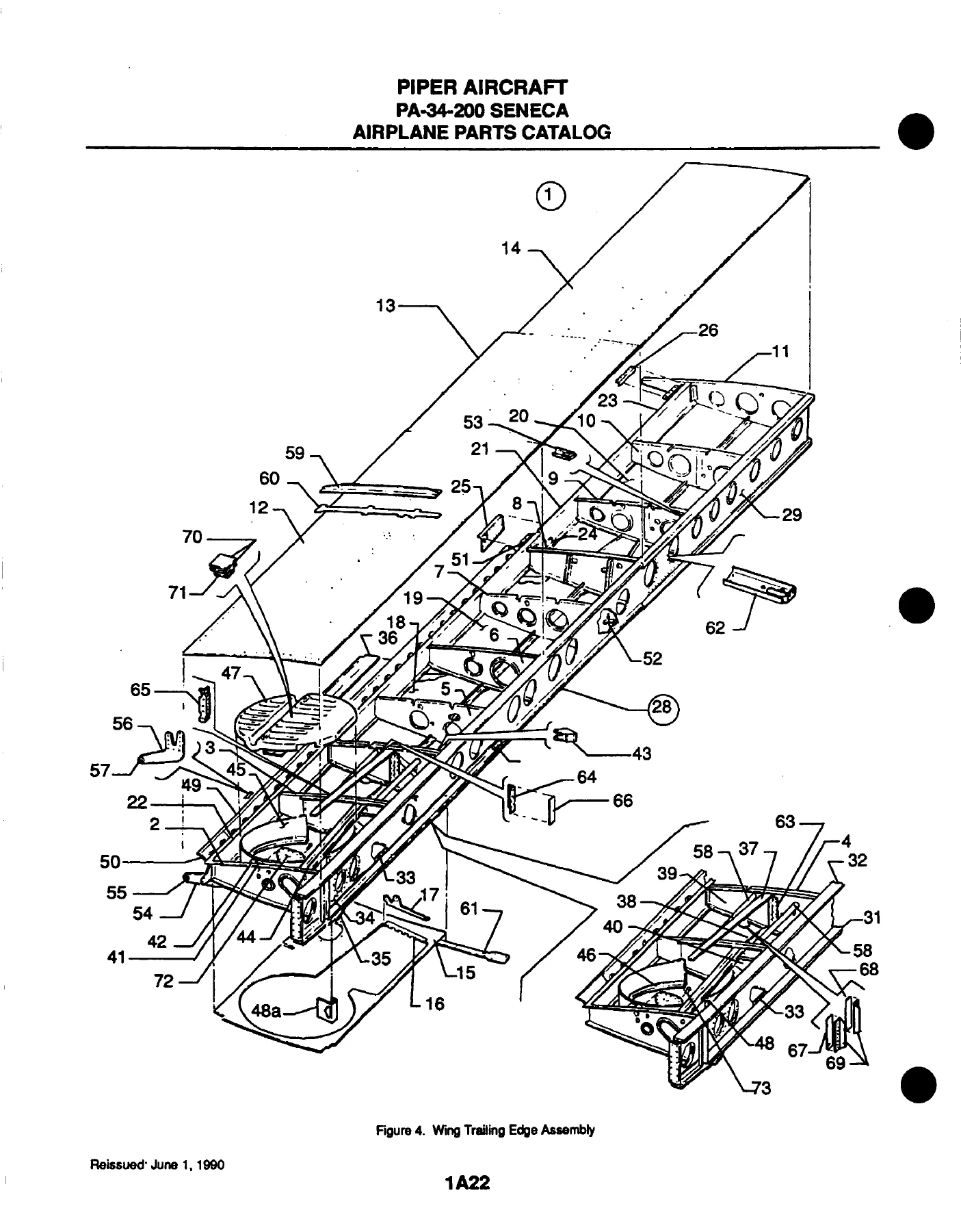
FIGURE 4. WING TRAILING EDGE ASSEMBLYp. 22
FIGURE 5. AILERON ASSEMBLYp. 27
FIGURE 6. FLAP ASSEMBLYp. 30
SECTION II – FUSELAGE GROUPp. 33
FIGURE 7. COMPLETE FUSELAGEp. 33
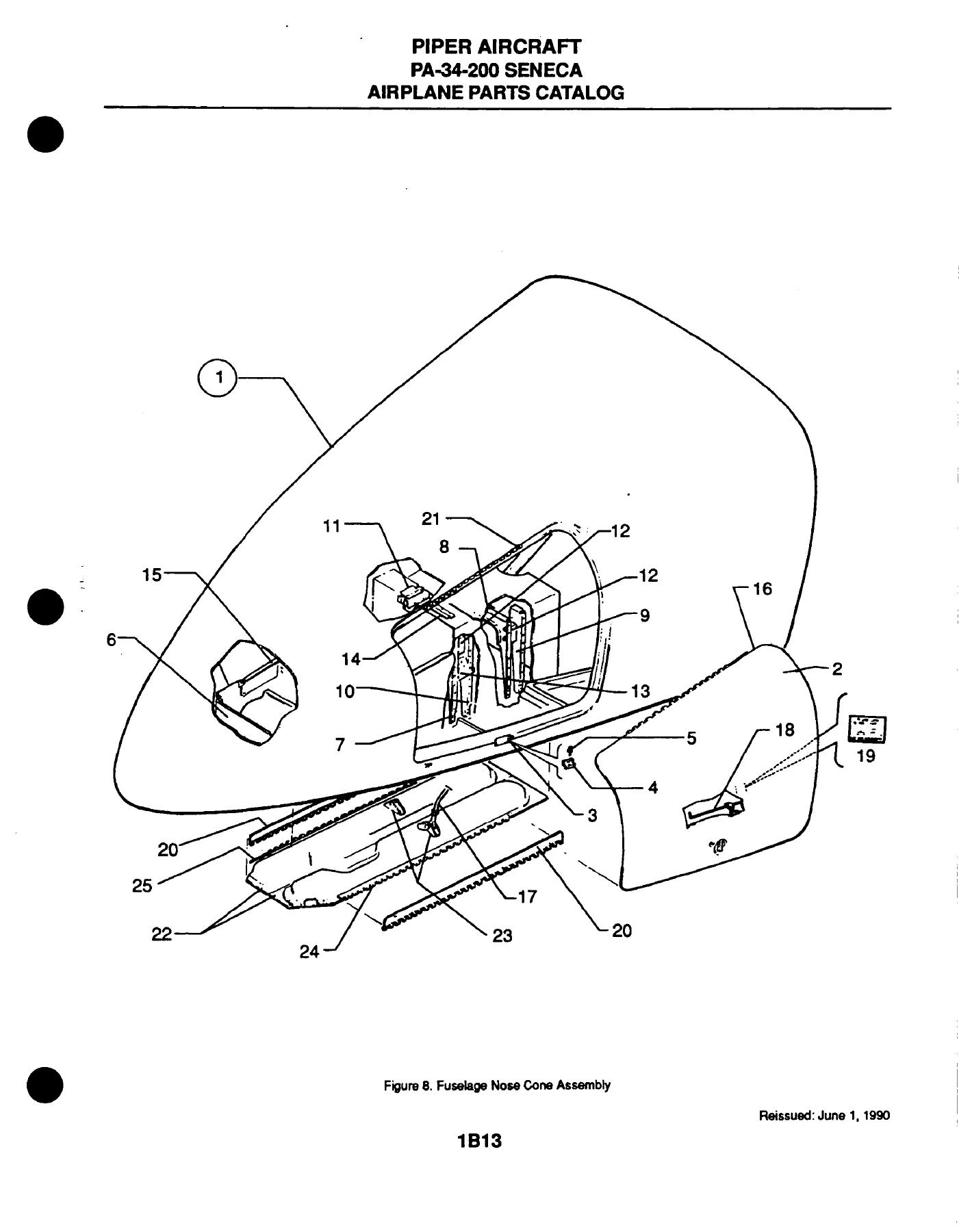
FIGURE 8. FUSELAGE NOSE CONE ASSEMBLYp. 37
FIGURE 9. FUSELAGE UPPER FORWARD COCKPIT ASSEMBLYp. 40
FIGURE 10. FUSELAGE UPPER CENTER COCKPIT ASSEMBLYp. 44
FIGURE 11. FUSELAGE UPPER AFT COCKPIT ASSEMBLYp. 49
FIGURE 12. FUSELAGE LOWER FORWARD COCKPIT ASSEMBLYp. 52
FIGURE 13. FUSELAGE LOWER AFT COCKPIT ASSEMBLYp. 56
FIGURE 14. FUSELAGE AFT SECTIONp. 60
FIGURE 15. FUSELAGE ENCLOSURE INSTALLATION (S/N 34-7250001 THRU 34-7250370)p. 64
FIGURE 15A. FUSELAGE ENCLOSURE INSTALLATION (S/N 34-7350001 THRU 34-7350363)p. 68
FIGURE 15B. FUSELAGE ENCLOSURE INSTALLATION (S/N 34-7450001 AND UP)p. 72
FIGURE 16. FUSELAGE FORWARD CABIN DOORp. 76
FIGURE 17. FUSELAGE AFT CABIN DOORp. 81
FIGURE 18. FUSELAGE AFT CARGO DOOR (S/N 34-7250001 THRU 34-7350363)p. 86
FIGURE 18A. FUSELAGE AFT CARGO DOOR (S/N 3407450001 AND UP)p. 89
FIGURE 19. FUSELAGE FORWARD BAGGAGE DOOR ASSEMBLYp. 92
SECTION III – TAIL SURFACES GROUPp. 95
FIGURE 20. TAIL SURFACES INSTALLATIONp. 95
FIGURE 21. STABILATOR ASSEMBLYp. 99
FIGURE 22. FIN ASSEMBLYp. 102
FIGURE 23. RUDDER ASSEMBLYp. 105
SECTION IV – LANDING GEAR GROUPp. 109
FIGURE 24. NOSE GEAR INSTALLATIONp. 109
FIGURE 25. NOSE GEAR ASSEMBLYp. 114
FIGURE 26. NOSE WHEEL ASSEMBLY (CLEVELAND)p. 118
FIGURE 26A. NOSE WHEEL ASSEMBLY (MCCAULEY)p. 121
FIGURE 27. MAIN GEAR INSTALLATIONp. 124
FIGURE 28. MAIN GEAR ASSEMBLYp. 128
FIGURE 29. MAIN WHEEL ASSEMBLYp. 133
FIGURE 30. BRAKE ASSEMBLYp. 136
FIGURE 31. NOSE AND MAIN GEAR DOOR ACTUATION INSTALLATIONSp. 139
FIGURE 32. HAND BRAKE INSALLATIONp. 142
FIGURE 33. TOE BRAKE INSTALLATIONp. 146
FIGURE 34. TOE BRAKE MASTER CYLINDER ASSEMBLYp. 149
SECTION V – CABIN EQUIPMENT GROUPp. 152
FIGURE 35. FORWARD BAGGAGE COMPARTMENT FINISHING INSTALLATIONp. 152
FIGURE 36. COCKPIT FINISHING INSTALLATIONp. 155
FIGURE 37. HEADLINER INSTALLATION (S/N 34-7250001 THRU 34-7350363)p. 162
FIGURE 37A. HEADLINER AND FORWARD FRESH AIR DUCT INSTALLATION (S/N 34-7450001 AND UP)p. 165
FIGURE 37B. AFT FRESH AIR DUCT INSTALLATION (S/N 34-7450001 AND UP)p. 169
FIGURE 38. CARPET INSTALLATIONp. 172
FIGURE 39. SEATS INSTALLATIONp. 178
FIGURE 40. VERTICALLY ADJUSTABLE FRONT SEAT ASSEMBLY (S/N 34-7250001 THRU 34-7450032)p. 184
FIGURE 41. VERTICALLY ADJUSTABLE FRONT SEAT ASSEMBLY (S/N 34-7450033 AND UP)p. 187
FIGURE 42. 7TH SEAT INSTALLATIONp. 191
SECTION VI – INSTRUMENTS GROUPp. 194
FIGURE 43. INSTRUMENT PANEL INSTALLATIONp. 194
FIGURE 44. VACUUM SYSTEM INSTALLATIONp. 199
FIGURE 45. PITOT STATIC SYSTEM INSTALLATIONp. 202
SECTION VII – POWER PLANT GROUPp. 206
FIGURE 46. POWER PLANT INSTALLATIONp. 206
FIGURE 47. PROPELLER ASSEMBLYp. 210
FIGURE 48. OIL COOLER INSTALLATIONp. 214
FIGURE 49. EXHAUST SYSTEM INSTALLATIONp. 217
FIGURE 50. ENGINE BAFFLE INSTALLATIONp. 220
FIGURE 51. ENGINE COWLING INSTALLATIONp. 223
FIGURE 52. ENGINE CONTROLS INSTALLATIONp. 226
FIGURE 53. QUADRANT ASSEMBLYp. 230
FIGURE 54. NACELLE ASSEMBLYp. 233
FIGURE 55. ENGINE INSTRUMENT LINES INSTALLATIONp. 236
SECTION VIII – FUEL SYSTEM GROUPp. 241
FIGURE 56. FUEL SYSTEM INSTALLATIONp. 241
FIGURE 57. FUEL TANK ASSEMBLIESp. 246
SECTION IX – CONTROL SYSTEM GROUPp. 249
FIGURE 58. AILERON CONTROL INSTALLATIONp. 249
FIGURE 59. RUDDER CONTOL INSTALLATIONp. 253
FIGURE 60. RUDDER TRIM INSTALLATIONp. 256
FIGURE 61. STABILATOR CONTROL INSTALLATIONp. 260
FIGURE 62. STABILATOR TRIM INSTALLATIONp. 263
FIGURE 63. FLAP CONTROL INSTALLATIONp. 267
FIGURE 64. CONTROL WHEEL INSTALLATIONp. 271
FIGURE 65. RUDDER PEDAL INSTALLATIONp. 275
SECTION X – HYDRAULIC SYSTEM GROUPp. 278
FIGURE 66. HYDRAULIC SYSTEM INSTALLATIONp. 278
SECTION XI – ENVIRONMENTAL GROUPp. 295
FIGURE 67. CABIN HEAT AND DEFROST SYSTEM (S/N 34-7250001 THRU 34-7250245)p. 295
FIGURE 68. CABIN HEAT AND DEFROST SYSTEM (S/N 34-7250246 AND UP)p. 299
FIGURE 69. COMBUSTION HEATER AND DUCT INSTALLATIONp. 303
FIGURE 70. JANITROL HEATER ASSEMBLYp. 307
FIGURE 71. COMBUSTION HEATER CONTROLS AND ELECTRICAL INSTALLATIONp. 310
FIGURE 72. COMBUSTION HEATER FUEL SYSTEM INSTALLATIONp. 313
FIGURE 73. JANITROL HEATER COMPONENTSp. 316
FIGURE 74. CABIN OVERHEAD AIR VENT INSTALLATION (S/N 34-7250001 THRU 34-7350363)p. 319
FIGURE 75. PNEUMATIC DEICING SYSTEM INSTALLATIONp. 322
SECTION XII – ELECTRICAL SYSTEM GROUPp. 325
FIGURE 76. ELECTRICAL SYSTEM INSTALLATIONp. 325
FIGURE 77. INSTRUMENT PANEL ELECTRICAL INSTALLATIONp. 329
FIGURE 78. STROBE LIGHTS INSTALLATIONp. 333
FIGURE 79. EXTERNAL POWER SUPPLY INSTALLATIONp. 336
FIGURE 80. LANDING LIGHT ASSEMBLYp. 339
FIGURE 81. ALTERNATOR ASSEMBLY (PRESTOLITE)p. 342
FIGURE 82. PROPELLER ELECTRIC DE-ICER INSTALLATIONp. 345
FIGURE 83. HEATED GLASS PANEL INSTALLATIONp. 348
SECTION XIII – ELECTRONICS GROUPp. 351
FIGURE 84. ELECTRIC PITCH TRIM INSTALLATIONp. 351
FIGURE 85. AUTOCONTROL III INSTALLATIONp. 355
FIGURE 86. ALTIMATIC PILOT III B-1 INSTALLATIONp. 358
FIGURE 87. ALTIMATIC V F/D-1 AUTOPILOT INSTALLATION (S/N 34-7350091 AND UP)p. 362
FIGURE 88. ALTIMATIC V-1 AUTOPILOT INSTALLATION (S/N 34-7350091 AND UP)p. 366
FIGURE 89. AUTOMATIC LOCATOR (ELT) INSTALLATION (GARRETT)p. 370
FIGURE 90. PIPER AUTOMATIC LOCATOR (ELT) INSTALLATION (COMMUNICATIONS COMPONENTS CORPORATION)p. 373
FIGURE 91. PIPER AUTOMATIC LOCATOR (ELT) INSTALLATION (NARCO AVIONICS)p. 376
FIGURE 92. RADIO, ANTENNA SYSTEM AND STATIC WICKS INSTALLATIONp. 379
FIGURE 93. AUDIO SELECTOR ASSEMBLYp. 382
FIGURE 94. PIPER PM-1 MARKER BEACON INSTALLATIONp. 385
RADIO INSTALLATION DRAWINGSp. 388
SECTION XIV – MISCELLANEOUS GROUPp. 389
FIGURE 95. PLACARDS AND EXTERIOR STENCILSp. 389
OPTIONAL EQUIPMENT AND REPAIR KITSp. 393
NUMERICAL INDEXp. 396

  • Section I – Wing Group: Wing installation, leading edge, trailing edge, aileron, and flap assemblies
  • Section II – Fuselage Group: Complete fuselage, nose cone, cockpit, cabin door, cargo door, and baggage door assemblies
  • Section III – Tail Surfaces Group: Stabilator, fin, and rudder assemblies
  • Section IV – Landing Gear Group: Nose gear, main gear, wheel, brake, and hydraulic actuation installations
  • Section V – Cabin Equipment Group: Baggage compartment, cockpit finishing, headliner, carpet, and seat installations
  • Section VI – Instruments Group: Instrument panel, vacuum system, and pitot static system installations
  • Section VII – Power Plant Group: Power plant installation, propeller assembly, oil cooler, exhaust system, engine baffle, cowling, controls, quadrant, nacelle, and instrument lines
  • Section VIII – Fuel System Group: Fuel system installation and fuel tank assemblies
  • Section IX – Control System Group: Aileron, rudder, stabilator, flap, control wheel, and rudder pedal installations
  • Section X – Hydraulic System Group: Hydraulic system installation
  • Section XI – Environmental Group: Cabin heat, defrost, combustion heater, overhead air vent, and pneumatic deicing systems
  • Section XII – Electrical System Group: Electrical system, instrument panel electrical, strobe lights, alternator, propeller deicer, and heated glass panel installations
  • Section XIII – Electronics Group: Autopilot, ELT, radio antenna systems, and audio selector installations
  • Section XIV – Miscellaneous Group: Placards, exterior stencils, and listing of optional equipment kits, repair kits, and special tools

This comprehensive Piper Seneca parts manual PDF is your key to correctly identifying and ordering any part for your aircraft. Each section includes detailed illustrations with index numbers and parts lists, showing the exact part number, description, quantity required, and specific serial number applicability. It also includes a numerical index for quickly locating any part.

IMAGES PREVIEW

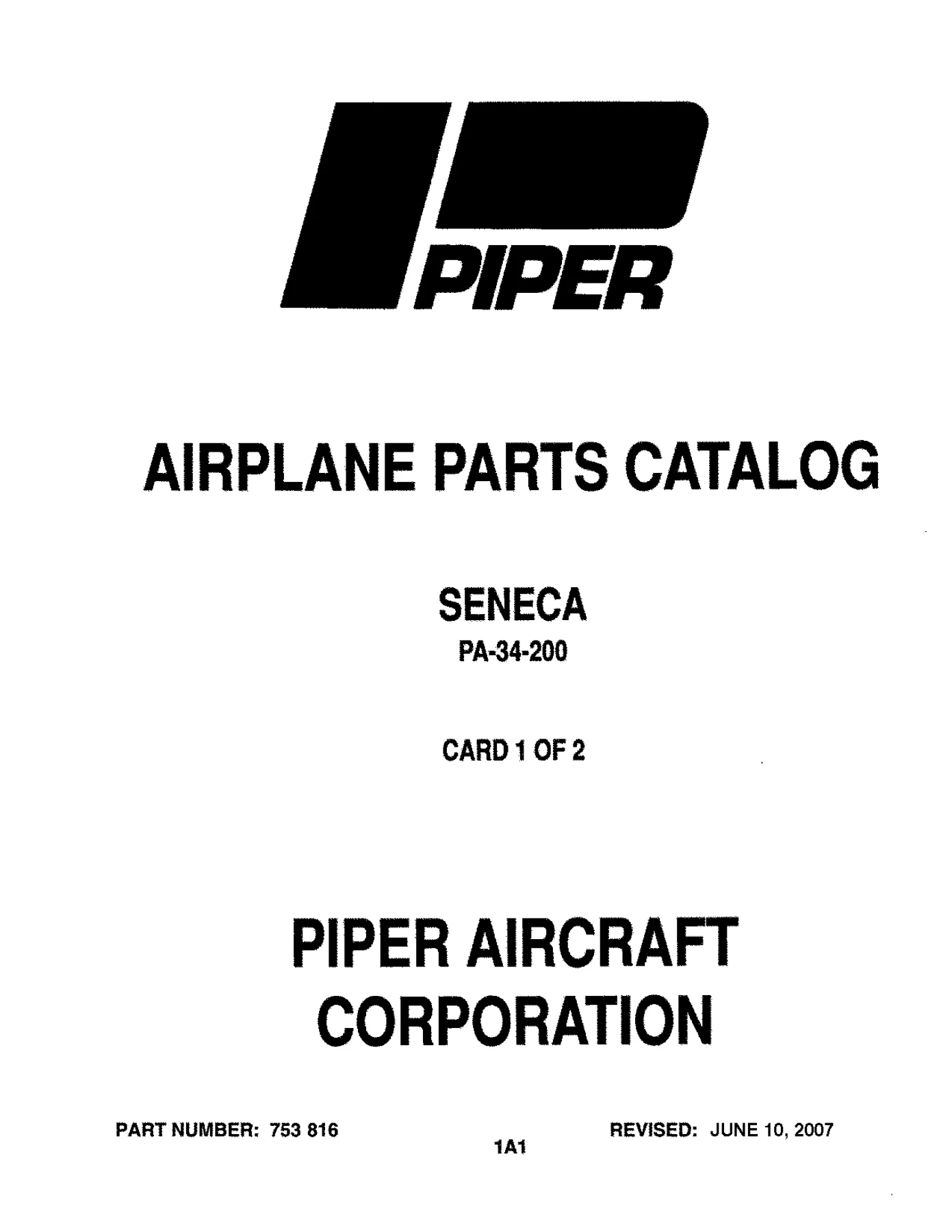
PA-34-200 Seneca Aircraft Parts Catalog 1971-1974 PDF Download — PDF page 1 preview
PA-34-200 Seneca Aircraft Parts Catalog 1971-1974 PDF Download — PDF page 22 preview
PA-34-200 Seneca Aircraft Parts Catalog 1971-1974 PDF Download — PDF page 37 preview

Why You Need This Manual

Whether you are a maintenance technician, aircraft owner, or restoration specialist, this PA-34-200 Seneca parts catalog download is an indispensable tool. Having the official parts documentation ensures you order the correct components for your specific serial number, avoiding costly mistakes and downtime. The detailed exploded views clarify how parts assemble, making it easier to understand system configurations and identify hidden or fastening parts.

Instant Digital Delivery

This is a digital PDF download, available immediately after purchase. You can view it on your computer, tablet, or smartphone, or print specific pages for use in your workshop. No shipping costs, no waiting – get the information you need right now to keep your Piper Seneca in top condition.
Reviews

There are no reviews yet.

Be the first to review “PA-34-200 Seneca Aircraft Parts Catalog 1971-1974 PDF Download”

What Our Customers Say

★★★★★ Live reviews from customers
Loading customer reviews...
0
    0
    Your Cart
    Your cart is emptyReturn to Shop
    🛒
    Recently Purchased
    🕒 verified order