★ TRUSTED BY 321,897+ PROFESSIONALS WORLDWIDE
🏢
Trusted Business
Verified & Licensed
🛡️
Virus Free Files
100% Safe Downloads
🔒
Secure Payment
SSL Protected
Instant Delivery
Available Immediately
Sale!

Gulfstream Twin Commander 690A & 690B Maintenance Manual – ATP Edition 2002 – PDF

Original price was: $39.95.Current price is: $23.95.

Complete ATP-formatted maintenance manual for the Gulfstream Twin Commander 690A and 690B, covering airframe, engine, hydraulic, electrical, and inspection procedures. Instant PDF download.

Instant PDF Download
Available immediately
💾
Save to Your Device
Download & keep forever
🛡️
Antivirus Scanned
100% virus-free
🌍
Trusted Worldwide
175,000+ customers

Description

Gulfstream Twin Commander 690A & 690B Maintenance Manual – ATP Edition 2002

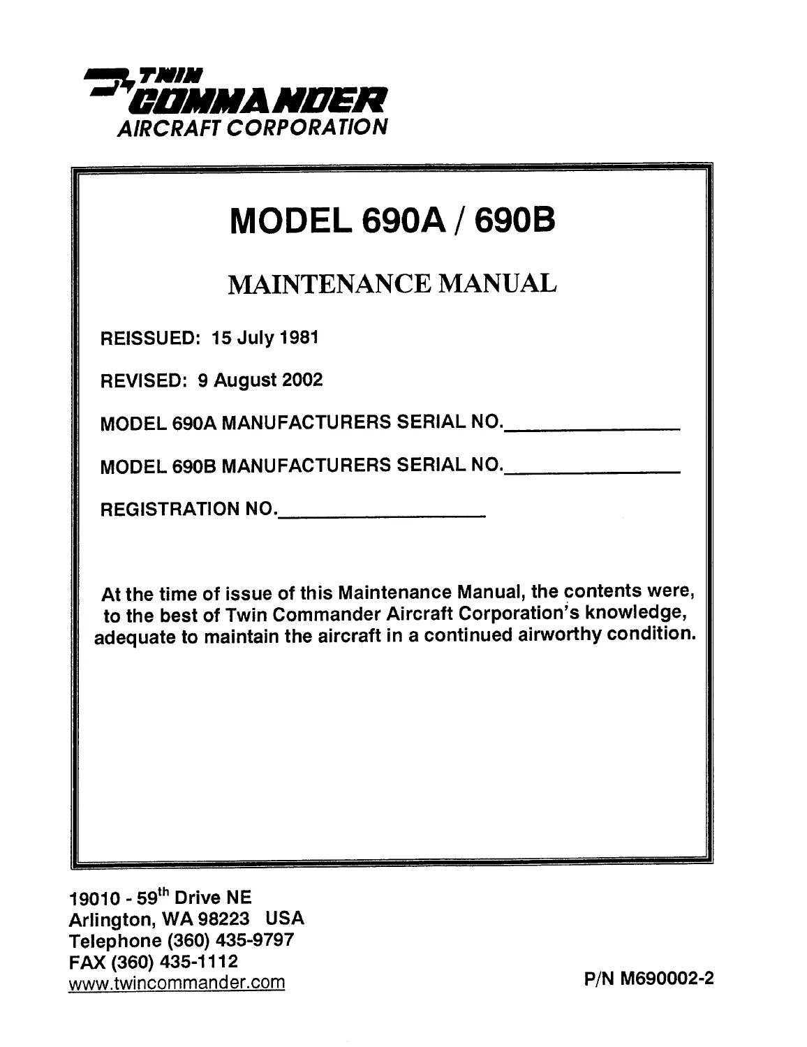
This Gulfstream Twin Commander 690A & 690B Maintenance Manual is the ATP Edition, reissued 15 July 1981 and revised through 9 August 2002 (Revision 4), covering both the Model 690A and Model 690B twin-engine pressurized executive aircraft. It is formatted by Aircraft Technical Publishers with a grid index cross-referencing the manufacturer’s original chapters, making it far easier to navigate than a photocopy of the factory book.

File Details

  • Manual type: Maintenance Manual (ATP-indexed reprint of Twin Commander Aircraft Corporation manual, P/N M690002-2)
  • Aircraft: Gulfstream Twin Commander 690A and 690B
  • Language: English
  • Page count: 749 pages
  • File format: PDF
  • Original issue: 15 July 1981; Revised: 9 August 2002

Chapters Covered

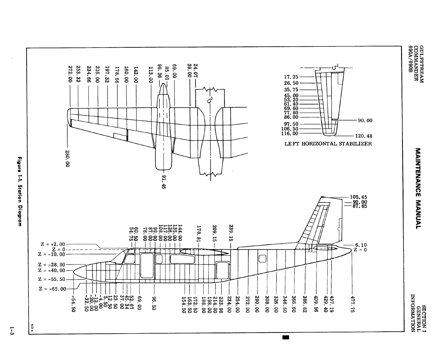
  • Section 1 – General Information: General Description, Principal Dimensions, Aircraft Structures (Fuselage, Wing, Empennage), Aircraft Systems overview
  • Section 2 – Servicing: Ground Handling (Towing, Taxiing, Parking, Mooring, Jacking, Leveling), Engine Ground Operation, Storage, Engine Oil System, Landing Gear and Brake System, Batteries, Fuel System, Hydraulic System, Environmental System, Oxygen System, Windshield Wiper System, Ice Protection System, Airframe Maintenance, Lubrication
  • Section 3 – Hydraulics: General Maintenance Practices, Functional Test Procedures, Hydraulic Reservoir, Shutoff Valves, Engine-Driven Hydraulic Pump, Accumulator-Regulator, Landing Gear-Wing Flap Control Valve, Landing Gear Actuating Cylinders, Auxiliary Hydraulic System
  • Section 4 – Power Plant: Engine Cowling and Mounting, Fire Detection System, Engine Control System, Oil and Fuel Systems, Ignition, Exhaust, Torque Sensing and Limiting Systems, Engine Preservation, Engine Removal/Buildup/Installation, Propeller Operation, Disassembly and Reassembly, Engine Controls and Rigging
  • Section 5 – Fuel System: Fuel Feed System, Fuel Sump, Shutoff Valve, Boost Pump, Fuel Cells (Removal, Repair, Installation), Fuel Quantity Indicating System, Approved Fuels
  • Section 6 – Landing Gear, Wheels and Brakes: Main and Nose Landing Gear Removal/Installation, Nose Wheel Steering, Position Indicators, Wheel and Brake Disassembly/Reassembly, Bleeding
  • Section 7 – Flight Controls: Control Cable Removal/Installation, Control Surface Balancing, Aileron/Rudder/Elevator Control Systems, Wing Flap Control System
  • Section 8 – Instruments: Vacuum System, Flight Instruments, Power Plant Instruments, Instrument Panel Removal/Installation, Stall Warning System
  • Section 9 – Environmental: Air Supply and Distribution, Refrigeration Unit, Cabin Pressure Controller, Oxygen System Checks and Repair
  • Section 10 – Electrical System: Power Distribution, Battery and Starter-Generator, Annunciator System, Lighting Circuits, Wiring Diagram Index Parts 1 and 2, Electrical Equipment Locator, Fuse Chart
  • Section 11 – Ice Protection System: Wing and Empennage Deicing, Propeller Deicing, Windshield and Rudder Anti-Icing
  • Section 12 – Optional Equipment: Emergency Locator Transmitter, Strobe Light System, Landing/Recognition Lights
  • Section 13 – Scheduled Inspection and Maintenance Requirements: 150 Hour Periodic Inspection Program, Phased Inspection Program (Phases A-D), Calendar Inspection Program, Major Inspection Guides, Dispatch Assurance Maintenance

Complete PDF Bookmark Tree

Complete Bookmarks

The complete bookmarks in the “Gulfstream Twin Commander 690A & 690B Maintenance Manual – ATP Edition 2002 – PDF” are as follows:

Home
Revision Letter
Indexp. 1
Title Pagep. 13
Record of Revisionsp. 15
Record of Temporary Revisionsp. 16
List of Effective Pagesp. 17
List of Chapters (Table of Contents)p. 25
Manufacturer's Introductionp. 28
1 General Informationp. 30
General Descriptionp. 31
Principal Dimensionsp. 31
Aircraft Structuresp. 32
Aircraft Systemsp. 35
2 Servicingp. 38
General Descriptionp. 39
Ground Handlingp. 39
Towingp. 39
Taxiingp. 41
Parkingp. 41
Mooringp. 41
Jackingp. 42
Levelingp. 42
Emergency Proceduresp. 42
Engine Ground Operationp. 43
Storagep. 43
Servicingp. 45
Engine Oil Systemp. 45
Landing Gear and Brake Systemp. 45
Batteriesp. 46
Fuel Systemp. 58
Hydraulic Systemp. 59
Environmental Systemp. 60
Oxygen Systemp. 60
Windshield Wiper Systemp. 61
Ice Protection Systemp. 64
Airframe Maintenancep. 64
Fuselage Sealingp. 64
Main Cabin Door Bayonet Rigging Checkp. 66
Cabin Door Sealp. 69
Windows and Windshieldsp. 70
Airframe Cleaningp. 71
Couch and Seatsp. 73
Structural Repairsp. 73
Lubricationp. 73
Interim Change Notice dated 05/15/87p. 79
Interim Change Notice dated 01/11/85p. 81
3 Hydraulicsp. 84
General Descriptionp. 85
General Maintenance Practicesp. 89
Functional Test Proceduresp. 89
Hydraulic System Componentsp. 90
Hydraulic Reservoirp. 90
Shutoff Valvesp. 90
Engine-Driven Hydraulic Pumpp. 91
Accumulator-Regulatorp. 92
Hydraulic Pressure Gagep. 94
Landing Gear-Wing Flap Control Valvep. 94
Main Landing Gear Actuating Cylindersp. 98
Main Landing Gear Uplock Cylinderp. 100
Nose Landing Gear Actuating Cylinderp. 102
Wing Flap Actuating Cylinderp. 102
Parking Brake Valvep. 103
Power Brake Valvesp. 104
Nose Wheel Steering Bypass Valvep. 106
Nose Wheel Steering Cylinderp. 106
Main Landing Gear Wheel Well Door Control Valvep. 107
Main Landing Gear Wheel Well Door Priority Valvesp. 108
Main Landing Gear Wheel Well Door Metering Valvep. 109
Main Landing Gear Door Actuating Cylindersp. 109
Auxiliary Hydraulic Systemp. 111
Auxiliary Hydraulic System Pumpp. 111
Auxiliary Hydraulic System Operational Checkp. 111
4 Power Plantp. 117
General Descriptionp. 118
Principles of Operationp. 118
Engine Cowlingp. 120
Engine Mountingp. 120
Fire Detection Systemp. 120
Engine Control Systemp. 120
Engine Accessories and Systemsp. 124
Accessoriesp. 124
Oil Systemp. 126
Fuel Systemp. 126
Fuel Purge Systemp. 129
Fuel Nozzles and Manifoldp. 129
Fuel Filterp. 129
Ignition Systemp. 131
Exhaust Systemp. 131
Torque Sensing Systemp. 137
Torque Limiting Systemp. 137
Horsepower Indicatorp. 139
Electrical Systemp. 139
Engine Preservationp. 141
Limited Preservationp. 141
Extended Preservationp. 141
Depreservationp. 141
Engine Changep. 141
Engine Removalp. 141
Engine Buildupp. 142
Engine Installationp. 143
Interim Change Notice dated 05/15/87p. 144
Propellerp. 147
Interim Change Notice dated 07/20/89p. 147
General Descriptionp. 153
Propeller Operationp. 153
Propeller Synchronization Systemp. 156
Propeller Disassemblyp. 164
Propeller Reassemblyp. 164
Engine Controlsp. 165
Fuel Control Unitp. 165
Propeller Controlsp. 167
Propeller Blade Angle Settingp. 169
Engine Control Riggingp. 170
Control Cablesp. 206
Handling and Storagep. 206
Installation Instructionsp. 206
5 Fuel Systemp. 209
General Descriptionp. 210
Fuel System Drainsp. 210
Defueling and Refuelingp. 211
Fuel Feed Systemp. 211
Fuel Sumpp. 211
Fuel Shutoff Valvep. 211
Fuel Boost Pumpp. 215
Fuel Screen and Fuel Filtersp. 215
Fuel Vent Systemp. 216
Fuel Cellsp. 216
Fuel Cell Removalp. 216
Fuel Cell Repairp. 217
Fuel Cell Installationp. 219
Wing Sealingp. 220
Fuel Quantity Indicating Systemp. 222
Fuel Quantity Indicatorsp. 222
Fuel Quantity Transmittersp. 222
Calibration – Fuel Quantity Systemp. 223
Calibration – Capacitance Fuel Systemp. 224
Fuel Low Lever Warning Systemp. 228
Fuel Flow Rate Indicating Systemp. 228
Fuel Flow Indicating System Maintenancep. 232
Approved Fuelsp. 232
6 Landing Gear, Wheels and Brakesp. 236
General Descriptionp. 237
Interim Change Notice dated 01/11/85p. 238
Landing Gear Operationp. 238
Operation Checkp. 239
Main Landing Gearp. 240
Strut Operationp. 240
Removalp. 242
Installationp. 245
Strut and Wheel Well Doorsp. 247
Uplocksp. 247
Nose Landing Gearp. 248
Removal and Disassemblyp. 248
Reassembly and Installationp. 250
Nose Wheel Steeringp. 251
Nose Gear Door Riggingp. 252
Interim Change Notice dated 05/15/87p. 252
Landing Gear Position Indicators & Warning Systemp. 254
Position Indicators Lightsp. 254
Warning Hornp. 257
Wheels and Brakesp. 257
General Descriptionp. 257
Main Wheel Removal and Disassemblyp. 258
Main Wheel Reassemblyp. 258
Main Wheel Installationp. 261
Measuring Brake Disk Wear Padsp. 261
Brake Removal and Disassemblyp. 261
Brake Reassembly and Installationp. 263
Brake and Nose Wheel Steering System Bleedingp. 265
Nose Wheel Removal and Disassemblyp. 266
Nose Wheel Reassembly and Installationp. 267
7 Flight Controlsp. 274
General Descriptionp. 275
Maintenance of Flight Controlsp. 275
Control Cable Removal and Installationp. 276
Control Surface Balancingp. 276
General Balance Proceduresp. 276
Balancing Instructionsp. 278
Balance Adjustmentp. 278
Flight Control Systemsp. 279
Control Columnsp. 279
Control Surface Trim Tab Free Playp. 280
Aileron Control Systemp. 284
Rudder Control Systemp. 288
Elevator Control Systemp. 292
Wing Flap Control Systemp. 295
Interim Change Notice dated 05/15/87p. 297
Wing Flap Position Transmitterp. 299
8 Instrumentsp. 304
General Descriptionp. 305
Instrument Vacuum Systemp. 306
Vacuum Relief Valvep. 307
Vacuum Control Valvep. 307
Vacuum Gagep. 307
Vacuum Air Filterp. 307
Flight Instrumentsp. 309
Pitot-Static Systemp. 309
Alternate Static Pressure Sourcep. 310
Airspeed Indicatorp. 310
Altimeterp. 313
Cabin Altitude and Differential Pressure Indicatorp. 313
Rate-of-Climb Indicatorp. 313
Cabin Rate-of-Climb Indicatorp. 313
Directional Gyro Indicatorp. 313
Altitude Gyro Indicatorp. 313
Turn-and-Bank Indicatorp. 313
Clockp. 314
Magnetic Compassp. 314
Flap Position Indicatorp. 314
Rudder and Elevator Trim Tab Position Indicatorp. 314
Aileron Trim Tab Position Indicatorp. 314
Power Plant Instrumentsp. 314
Engine Gage Unitsp. 314
Tachometer Indicators and Generatorsp. 318
Horsepower Indicatorsp. 318
Inter Turbine Temperature Systemp. 318
Fuel Flow Rate Indicatorsp. 318
Fuel Consumed Totalizerp. 318
Miscellaneous Instrumentsp. 319
Hydraulic Pressure Gagep. 319
Regulated Bleed Air Pressure Gagep. 319
Fuel Quantity Indctr-Cntr Wing & Lwr Fus Fuel Cellsp. 319
Voltammetersp. 319
Outside Air Temperature Indicator-Ambient Airp. 319
Instrument Panelp. 319
Removal and Installationp. 319
Instrumentsp. 320
Removal and Installationp. 320
Stall Warning Systemp. 320
9 Environmentalp. 325
General Descriptionp. 326
Principles of Operationp. 330
Air Supply and Distributionp. 330
Environmental System Componentsp. 330
Environmental System Jet Pump Assemblyp. 330
Refrigeration Unitp. 330
Water Separatorp. 332
Ground Blowerp. 332
Defog Blowerp. 332
Air Transition Tube and Plenump. 333
Environmental System Controlsp. 333
Cabin Pressure Controllerp. 333
Cabin Pressurization System-Functional Testp. 337
Cabin Temperature Controlsp. 339
Environmental Electrical System-Functional Testp. 340
Oxygen Systemp. 342
Generalp. 342
Oxygen System Checks and Repairp. 342
10 Electrical Systemp. 353
General Descriptionp. 354
Power Distributionp. 354
Batteryp. 357
Battery Temperature Monitoring Systemp. 357
External Powerp. 357
Starter-Generatorp. 360
Circuit Breaker Panelp. 364
Annunciator Systemp. 365
Annunciator Panel Lamp Replacementp. 365
Lighting System Circuitsp. 365
Interior Lightsp. 365
Exterior Lightsp. 366
Hydraulic System Circuitsp. 367
Hydraulic Shutoff Valvep. 367
Auxiliary Hydraulic Pumpp. 368
Power Plant Circuitsp. 368
Propeller Unfeathering Pumpsp. 368
Fuel System Circuitsp. 368
Fuel Boost Pumps and Shutoff Valvesp. 368
Fuel Quantity Indicatorp. 368
Fuel Vent Heatersp. 369
Instrument Circuitsp. 369
Stall Warning Systemp. 370
Tachometer-Generatorp. 370
Beta Lightsp. 371
Rudder and Elevator Trim Tab Position Indicatorsp. 371
Aileron Trim Tab Position Indicatorp. 373
Wing Flap Position Indicatorp. 373
Pitot and Stall Warning Heatersp. 374
Miscellaneous Circuitsp. 374
Cabin Door Lock and Warning Lightp. 374
Cigarette Lighterp. 375
Electric Windshield Wiperp. 375
Spare Wiresp. 376
Electrical System Referencep. 376
Electrical Diagramsp. 376
Wiring Diagram Index – Part 1p. 381
Battery and Bus Systemp. 383
Electrical Power Distributionp. 385
Electrical Equipment Locatorp. 387
Connector and T-Strip Locatorp. 395
Fuse Chartp. 396
Left Starter-Generator Circuitp. 397
Right Starter-Generator Circuitp. 404
Power Distribution Systemp. 411
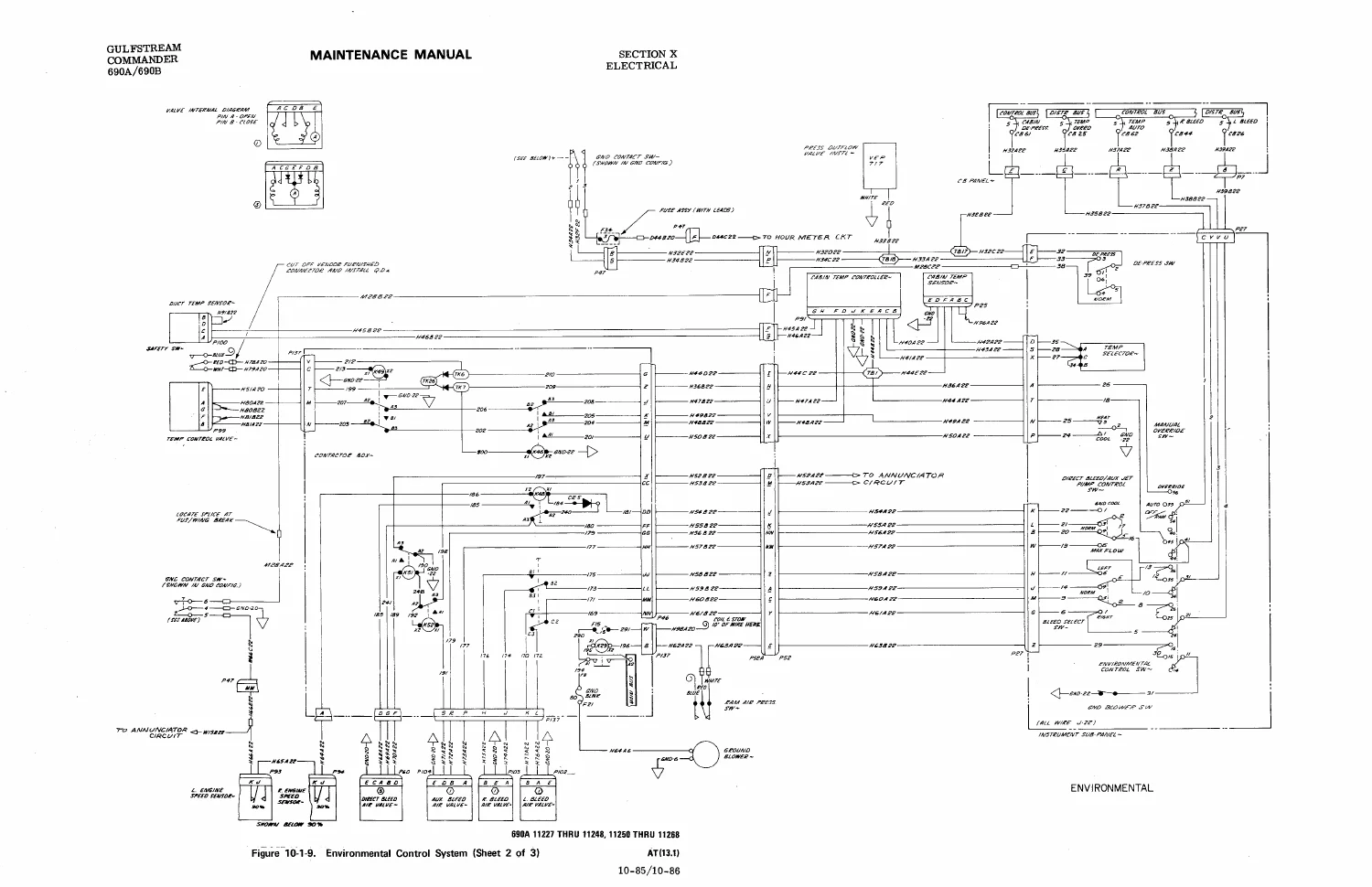
Environmental Control Systemp. 414
Ice Protection Systemp. 417
Flight Control Circuitsp. 422
Fuel Systemp. 425
Hydraulic Control Systemp. 430
Annunciator Circuitsp. 433
Engine Indication Systemp. 437
Landing Gear Positionp. 439
Exterior Lightingp. 442
Interior Lightingp. 444
Miscellaneous Circuitsp. 447
Interior Optionsp. 453
Wiring Diagram Index Part – 2p. 469
Battery and Bus Systemp. 470
Electrical System Diagramp. 471
Electrical Equipment Locatorp. 472
Connector and T-Strip Locatorp. 475
Fuse Chartp. 476
Parts Listp. 477
Component Identification and Codingp. 479
Left Starter-Generator Systemp. 480
Right Starter-Generator Systemp. 484
Power Distribution Systemp. 488
Engine Indicatorsp. 489
Fuelp. 498
Hydraulicsp. 501
Environmentalp. 502
Control Surfacesp. 503
De-Icingp. 504
Annunciation (Gear Position & Stall Warning)p. 508
Annunciationp. 510
Interior Lightingp. 513
Exterior Lightingp. 517
Miscellaneousp. 518
Interior Optionsp. 524
11 Ice Protection Systemp. 543
General Descriptionp. 544
Wing and Empennage Deicing Systemp. 544
Deicer System Componentsp. 544
Deicer System Controlsp. 546
Deicer Boot Maintenance and Repairp. 546
Deicer System Operational Checkp. 549
Propeller Deicing Systemp. 549
Propeller Deicing System Maintenancep. 550
Generation Inlet Anti-Icing Systemp. 553
Anti-Ice Boot Element Checkp. 553
Windshield Anti-Ice Systemp. 553
Wing Ice Inspection Lightsp. 553
Rudder Anti-Icing Systemp. 553
Rudder Anti-Icing System Maintenancep. 553
12 Optional Equipmentp. 555
General Descriptionp. 556
Emergency Locator Transmitter Systemp. 556
Battery Replacementp. 556
Strobe Light Systemp. 557
Strobe Light Removal and Installationp. 557
Retractable High Speed Landing/Recognition Lightsp. 557
Landing Light Lamp Removal and Installationp. 557
13 Scheduled Inspection and Maintenance Requirementsp. 558
Maintenance Requirementsp. 560
General Instructionsp. 563
Definitionsp. 564
Maintenance Limits Schedulep. 565
150 Hour Periodic Inspection Programp. 569
Phased Inspection Programp. 591
Phase "A"p. 591
Phase "B"p. 604
Phase "C"p. 616
Phase "D"p. 629
Calendar Inspection Programp. 642
Check "A"p. 642
Check "A1"p. 657
Check "B1"p. 674
Check "C1"p. 691
Check "D1"p. 708
Interim Change Notice dated 01/11/85p. 725
Major Inspection – Guide Ip. 728
Major Inspection – Guide IIp. 729
Abnormal Ground Loads Inspection Schedulep. 730
Abnormal Flight Loads Inspection Schedulep. 732
Lightning Strike Inspection Schedulep. 734
Main Landing Gear Major Inspection Program – Guide IIIp. 735
Nose Landing Gear Major Inspection Program – Guide IVp. 737
Dispatch Assurance Maintenancep. 739
Preflight Inspectionp. 740
Interim Change Notice dated 04/07/86p. 741
Turn-Around Inspectionp. 743
Postflight Inspectionp. 745
Routine Inspectionp. 747
End of TOCp. 749

Taken together, this Twin Commander 690A/690B maintenance manual gives a technician everything needed to service the airframe, power plant, and systems of this AiResearch TPE331-powered pressurized twin from routine servicing through scheduled heavy inspections.

Aircraft Overview

The Twin Commander 690A/690B is a high-wing, twin-engine pressurized aircraft built for executive transport, powered by two AiResearch TPE331-5-251K turboprop engines driving Hartzell three-blade constant-speed propellers, with a certified altitude capability up to 31,000 feet. The manual details the all-metal wing and fuselage structure, retractable tricycle landing gear with independent pneumatic gear extension backup, and the environmental system that automatically manages cabin temperature and pressurization.

IMAGES PREVIEW

Gulfstream Twin Commander 690A & 690B Maintenance Manual - ATP Edition 2002 - PDF — PDF page 14 preview
Gulfstream Twin Commander 690A & 690B Maintenance Manual - ATP Edition 2002 - PDF — PDF page 33 preview
Gulfstream Twin Commander 690A & 690B Maintenance Manual - ATP Edition 2002 - PDF — PDF page 415 preview

Why Technicians Rely on This Manual

This Gulfstream Twin Commander 690A & 690B Maintenance Manual gives an A&P mechanic or maintenance shop the correct factory-based procedures for hydraulic component servicing, engine removal and installation, propeller disassembly, landing gear and brake overhaul, electrical troubleshooting via the full wiring diagram index, and compliance with the 150-hour, Phased, and Calendar inspection programs. Following the exact torque values, capacities, and rigging procedures in this manual – rather than guessing at generic specs – is what keeps the aircraft airworthy and inspections defensible.

This Twin Commander 690A/690B manual downloads instantly as a PDF after purchase – no shipping, no waiting. Read it on a laptop, tablet, or phone in the hangar, or print any section you need at the workbench.
Reviews

There are no reviews yet.

Be the first to review “Gulfstream Twin Commander 690A & 690B Maintenance Manual – ATP Edition 2002 – PDF”

What Our Customers Say

★★★★★ Live reviews from customers
Loading customer reviews...
0
    0
    Your Cart
    Your cart is emptyReturn to Shop
    🛒
    Recently Purchased
    🕒 verified order