★ TRUSTED BY 321,897+ PROFESSIONALS WORLDWIDE
🏢
Trusted Business
Verified & Licensed
🛡️
Virus Free Files
100% Safe Downloads
🔒
Secure Payment
SSL Protected
Instant Delivery
Available Immediately
Sale!

Airbus A318/A319/A320/A321 Air Conditioning Maintenance Manual – AMM Chapter 21

Original price was: $44.95.Current price is: $29.95.

Complete Airbus AMM Chapter 21 for A318/A319/A320/A321, covering air conditioning, pressurization, cooling, and temperature control systems.

SKU: AMM-A320-CHAPTER21-DL Category: Tags: , , , Vendor: ServiceDeskPDFs
Instant PDF Download
Available immediately
💾
Save to Your Device
Download & keep forever
🛡️
Antivirus Scanned
100% virus-free
🌍
Trusted Worldwide
175,000+ customers

Description

File Details

  • Manual Type: Aircraft Maintenance Manual (AMM) Chapter 21
  • Applicable Aircraft: Airbus A318, A319, A320, A321
  • Language: English
  • Page Count: Approximately 1909 pages
  • File Format: PDF
  • Document Number: AES
  • Revision: 40
  • Date: May 01/12

This comprehensive chapter of the Airbus AMM provides all the detailed technical information, diagrams, and procedures required for the maintenance, testing, and troubleshooting of the entire air conditioning system on A318, A319, A320, and A321 aircraft.

Chapters Covered

The manual is organized into the following major sections, which are further broken down into detailed tasks and procedures:

IMAGES PREVIEW

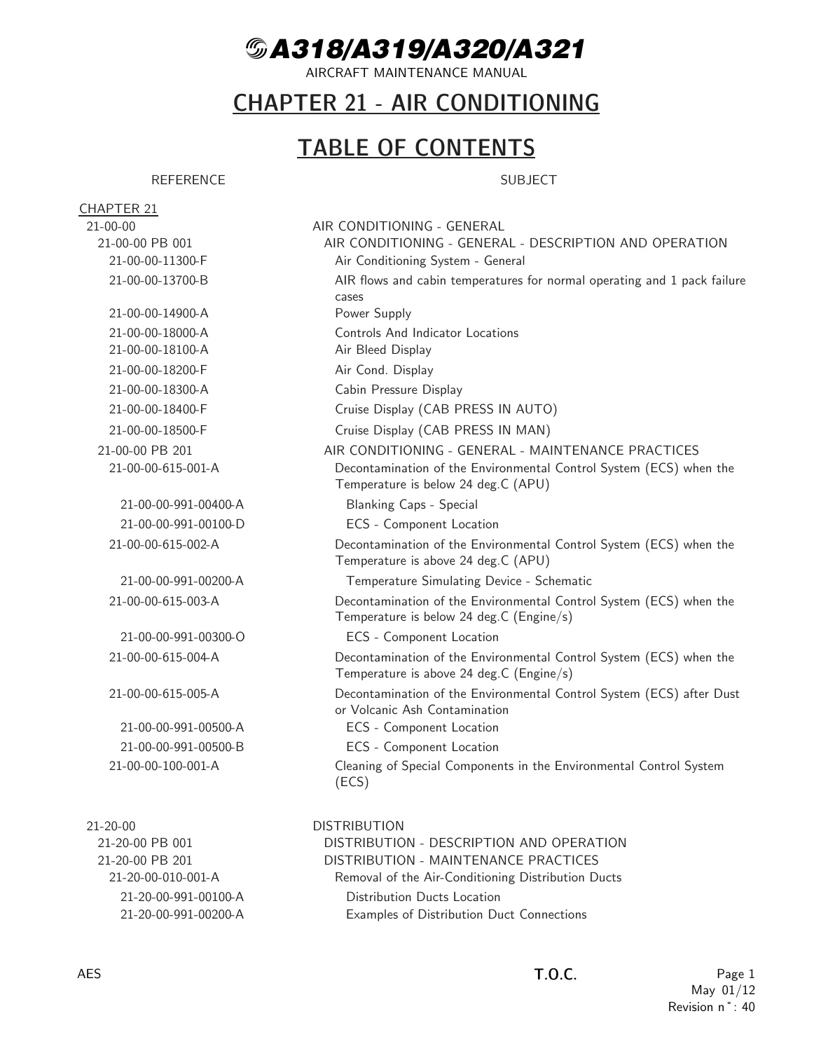
Airbus A318/A319/A320/A321 Air Conditioning Maintenance Manual - AMM Chapter 21 — PDF page 1 preview
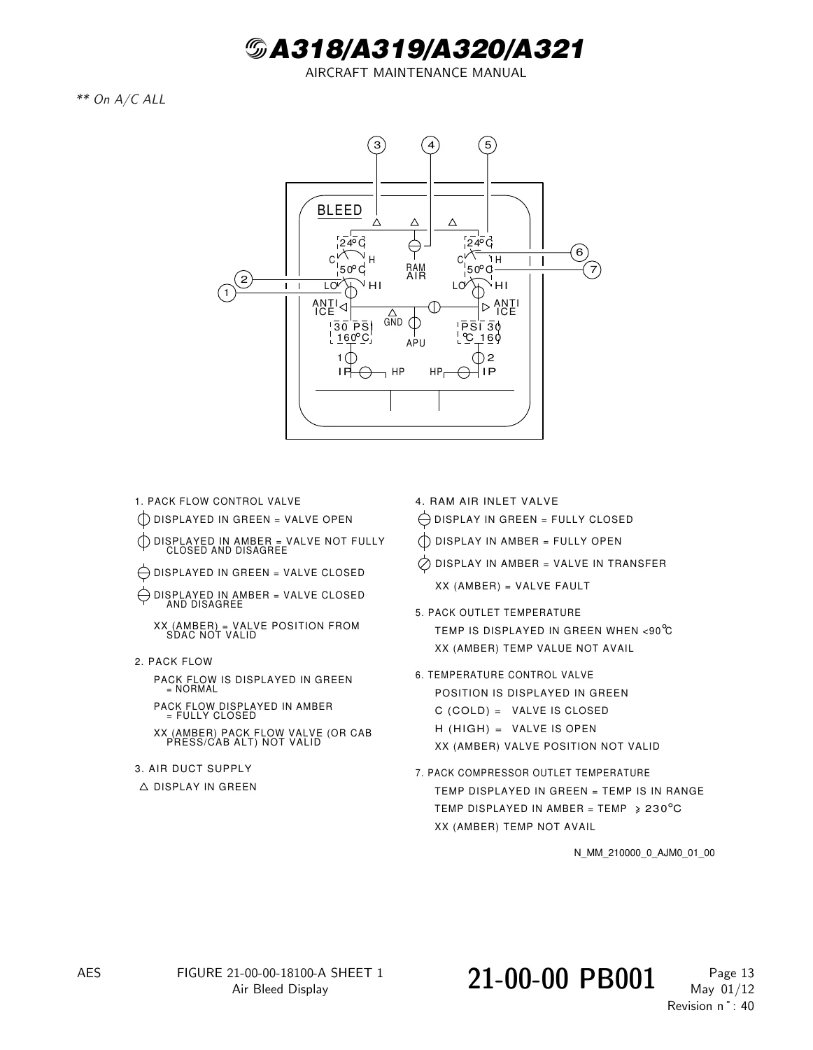
Airbus A318/A319/A320/A321 Air Conditioning Maintenance Manual - AMM Chapter 21 — PDF page 40 preview
Airbus A318/A319/A320/A321 Air Conditioning Maintenance Manual - AMM Chapter 21 — PDF page 41 preview

  • 21-00-00 AIR CONDITIONING – GENERAL: System description, operation, control and indicating, BITE test, and general maintenance practices including decontamination procedures for the Environmental Control System (ECS).
  • 21-20-00 DISTRIBUTION: Removal/installation of distribution ducts, and inspection of riser ducts and lavatory/galley ventilation ducting.
  • 21-21-00 AIR DISTRIBUTION AND RECIRCULATION: Component location, system description, operational tests for recirculation fans and individual air outlets. Covers recirculation filters, check valves, and the mixer unit.
  • 21-23-00 LAVATORY/GALLEY VENTILATION: Description, component location, servicing (replacement of extraction filter), deactivation/reactivation, and functional tests.
  • 21-24-00 INDIVIDUAL AIR DISTRIBUTION: Description, repair of individual air outlets, and removal/installation of the outlets.
  • 21-26-00 AVIONICS EQUIPMENT VENTILATION: Full system description, component location, operation, BITE tests, maintenance practices, deactivation/reactivation of valves and fans, and extensive adjustment/test procedures.
  • 21-28-00 CARGO COMPARTMENT VENTILATION: Description, component location, deactivation/reactivation, functional and operational tests, plus removal/installation of the ventilation controller, isolation valves, and extraction fan.
  • 21-31-00 PRESSURE CONTROL AND MONITORING: Detailed system description, component location, operation, BITE test, servicing, deactivation/reactivation, adjustment/test, cleaning, and removal/installation of controllers, outflow valve, and safety valves.
  • 21-43-00 CARGO COMPARTMENT HEATING: Description, component location, system description, BITE test, deactivation/reactivation, adjustment/test, cleaning, and removal/installation of sensors, selector, controller, and valves.
  • 21-51-00 FLOW CONTROL AND INDICATING: Description, component location, system description, operation, BITE test, deactivation/reactivation, adjustment/test, inspection/check, repairs, and removal/installation of sensors, filters, and valves.
  • 21-52-00 AIR COOLING SYSTEM: Full system description, component location, operation, BITE test, servicing, deactivation/reactivation, extensive adjustment/tests, inspection/check, cleaning/painting, repairs, and removal/installation of the air cycle machine, heat exchangers, condenser, water extractor, and other pack components.
  • 21-55-00 EMERGENCY RAM AIR INLET: Description, component location, system description, operation, deactivation/reactivation, adjustment/test, and removal/installation of the actuator and check valve.
  • 21-61-00 PACK TEMPERATURE CONTROL: Description, component location, system description, operation, BITE test, deactivation/reactivation, adjustment/test, repairs, and removal/installation of pack controllers, sensors, and valves.
  • 21-63-00 COCKPIT AND CABIN TEMPERATURE CONTROL: Description, component location, system description, operation, BITE test, servicing, deactivation/reactivation, adjustment/test, and removal/installation of temperature selectors, sensors, and valves.

Complete PDF Bookmark Tree

Complete Bookmarks

The complete bookmarks in the “Airbus A318/A319/A320/A321 Air Conditioning Maintenance Manual – AMM Chapter 21” are as follows:

Manual Front Matter
Chapter 05 – TIME LIMITS – MAINTENANCE CHECKS
Chapter 06 – DIMENSIONS AND AREAS
Chapter 07 – LIFTING AND SHORING
Chapter 08 – LEVELING AND WEIGHING
Chapter 09 – TOWING AND TAXIING
Chapter 10 – PARKING, MOORING, STORAGE & RETURN TO SERVICE
Chapter 11 – PLACARDS AND MARKINGS
Chapter 12 – SERVICING
Chapter 20 – STANDARD PRACTICES – AIRFRAME
Chapter 21 – AIR CONDITIONINGp. 1
Table of Contentsp. 1
21-00 – AIR CONDITIONING – GENERALp. 28
21-00-00 – AIR CONDITIONING – GENERALp. 28
21-00-00 PB 001 CONF 00 – AIR CONDITIONING – GENERAL – DESCRIPTION AND OPERATIONp. 28
Generalp. 28
System Descriptionp. 29
Power Supplyp. 31
Interfacep. 32
Operation/Control and Indicatingp. 33
Bite Testp. 34
Figure 21-00-00-11300-F – Air Conditioning System – Generalp. 35
Figure 21-00-00-13700-B – AIR flows and cabin temperatures for normal operating and 1 pack failure casesp. 36
Figure 21-00-00-14900-A – Power Supplyp. 37
Figure 21-00-00-18000-A – Controls And Indicator Locationsp. 39
Figure 21-00-00-18100-A – Air Bleed Displayp. 40
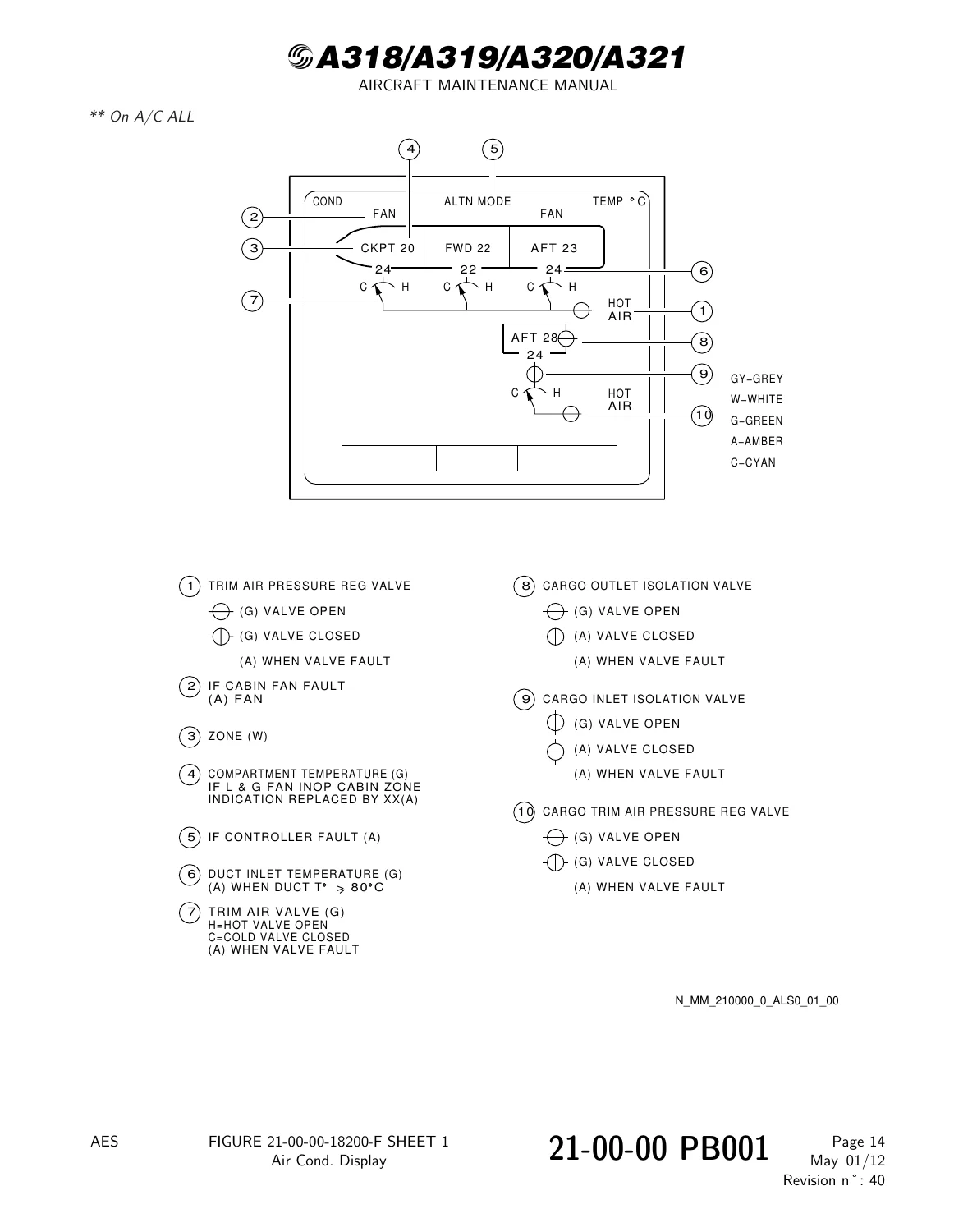
Figure 21-00-00-18200-F – Air Cond. Displayp. 41
Figure 21-00-00-18300-A – Cabin Pressure Displayp. 42
Figure 21-00-00-18400-F – Cruise Display (CAB PRESS IN AUTO)p. 43
Figure 21-00-00-18500-F – Cruise Display (CAB PRESS IN MAN)p. 44
21-00-00 PB 201 CONF 00 – AIR CONDITIONING – GENERAL – MAINTENANCE PRACTICESp. 45
21-00-00-615-001-A – Decontamination of the Environmental Control System (ECS) when the Temperature is below 24 deg.C (APU)p. 45
Figure 21-00-00-991-00400-A – Blanking Caps – Specialp. 64
Figure 21-00-00-991-00100-D – ECS – Component Locationp. 65
21-00-00-615-002-A – Decontamination of the Environmental Control System (ECS) when the Temperature is above 24 deg.C (APU)p. 66
Figure 21-00-00-991-00200-A – Temperature Simulating Device – Schematicp. 86
21-00-00-615-003-A – Decontamination of the Environmental Control System (ECS) when the Temperature is below 24 deg.C (Engine/s)p. 87
Figure 21-00-00-991-00300-O – ECS – Component Locationp. 106
21-00-00-615-004-A – Decontamination of the Environmental Control System (ECS) when the Temperature is above 24 deg.C (Engine/s)p. 107
21-00-00-615-005-A – Decontamination of the Environmental Control System (ECS) after Dust or Volcanic Ash Contaminationp. 127
Figure 21-00-00-991-00500-A – ECS – Component Locationp. 131
Figure 21-00-00-991-00500-B – ECS – Component Locationp. 132
21-00-00-100-001-A – Cleaning of Special Components in the Environmental Control System (ECS)p. 133
21-20 – DISTRIBUTIONp. 136
21-20-00 – DISTRIBUTIONp. 136
21-20-00 PB 001 CONF 00 – DISTRIBUTION – DESCRIPTION AND OPERATIONp. 136
Generalp. 136
System Descriptionp. 137
21-20-00 PB 201 CONF 00 – DISTRIBUTION – MAINTENANCE PRACTICESp. 138
21-20-00-010-001-A – Removal of the Air-Conditioning Distribution Ductsp. 138
Figure 21-20-00-991-00100-A – Distribution Ducts Locationp. 141
Figure 21-20-00-991-00200-A – Examples of Distribution Duct Connectionsp. 142
Figure 21-20-00-991-00300-A – Examples of Distribution Duct Attachment Methodsp. 143
21-20-00-410-001-A – Installation of the Air-Conditioning Distribution Ductsp. 144
21-20-00 PB 601 CONF 00 – DISTRIBUTION – INSPECTION/CHECKp. 149
21-20-00-210-001-A – General Visual Inspection of the Riser Ducts in the Passenger Compartmentp. 149
Figure 21-20-00-991-00400-A – Riser Ducts – General Component Locationp. 153
Figure 21-20-00-991-00600-A – Riser Duct/Dado Panel – Critical Distancep. 154
21-20-00-210-002-A – General Visual Inspection of Lavatory and Galley Ventilation Ducting (Zones 210 to 260)p. 155
21-21 – AIR DISTRIBUTION AND RECIRCULATIONp. 158
21-21-00 – AIR DISTRIBUTION AND RECIRCULATIONp. 158
21-21-00 PB 001 CONF 00 – AIR DISTRIBUTION AND RECIRCULATION – DESCRIPTION AND OPERATIONp. 158
Generalp. 158
Component Locationp. 159
System Descriptionp. 160
Power Supplyp. 162
Component Descriptionp. 163
Operation/Control and Indicatingp. 164
Figure 21-21-00-12900-A – Air Distribution and Recirculation – Component Locationp. 165
Figure 21-21-00-16000-A – Air Distribution – Passenger Cabinp. 167
Figure 21-21-00-16100-A – Air Distribution – Cockpitp. 168
Figure 21-21-00-16200-A – Air Distribution – Mixer Unitp. 169
Figure 21-21-00-17400-A – Cabin Fans – Schematicp. 170
Figure 21-21-00-19500-A – Recirculation Fanp. 171
Figure 21-21-00-21200-A – Controls and Indicationsp. 172
21-21-00 PB 501 CONF 00 – AIR DISTRIBUTION AND RECIRCULATION – ADJUSTMENT/TESTp. 173
21-21-00-710-001-A – Operational Test of the Cabin Recirculation Fans 14HG and 15HG.p. 173
21-21-00-710-002-A – Operational Test of the Individual Air Outletp. 177
21-21-41 – FILTER – RECIRCULATIONp. 179
21-21-41 PB 301 CONF 00 – FILTER – RECIRCULATION – SERVICINGp. 179
21-21-41-920-002-A – Scheduled Replacement of the Recirculation Filter 4012HMp. 179
Figure 21-21-41-991-00300-A – Recirculation Filterp. 180
21-21-41 PB 401 CONF 00 – FILTER – RECIRCULATION – REMOVAL/INSTALLATIONp. 181
21-21-41-000-001-A – Removal of the Recirculation Filter 4012HMp. 181
Figure 21-21-41-991-00100-A – Recirculation Filterp. 184
21-21-41-400-001-A – Installation of the Recirculation Filter 4012HMp. 185
21-21-42 – CHECK VALVEp. 188
21-21-42 PB 401 CONF 00 – CHECK VALVE – REMOVAL/INSTALLATIONp. 188
21-21-42-000-001-A – Removal of the Recirculation Check Valve 4020HMp. 188
Figure 21-21-42-991-00100-A – Recirculation Check Valve 4020HM (4021HM).p. 190
21-21-42-400-001-A – Installation of the Recirculation Check Valve 4020HMp. 191
21-21-43 – MIXER UNITp. 194
21-21-43 PB 401 CONF 00 – MIXER UNIT – REMOVAL/INSTALLATIONp. 194
21-21-43-000-001-A – Removal of the Mixer Unitp. 194
Figure 21-21-43-991-00100-A – Mixer Unit.p. 197
21-21-43-000-002-A – Removal of the lower part of the Mixer Unitp. 200
Figure 21-21-43-991-00200-A – Lower part of the mixer unitp. 202
21-21-43-400-002-A – Installation of the Mixer Unitp. 203
21-21-43-400-003-A – Installation of the lower part of the Mixer Unitp. 209
21-21-44 – AIR OUTLET – INDIVIDUAL, COCKPITp. 213
21-21-44 PB 401 CONF 00 – AIR OUTLET – INDIVIDUAL, COCKPIT – REMOVAL/INSTALLATIONp. 213
21-21-44-000-001-A – Removal of the CAPT (F/O) Individual Air-Outletp. 213
Figure 21-21-44-991-00100-B – CAPT (F/O) Individual Air-Outletp. 215
21-21-44-400-001-A – Installation of the CAPT (F/O) Individual Air-Outletp. 216
21-21-44-000-002-A – Removal of the Third (Fourth) Occupant Individual Air-Outletp. 218
Figure 21-21-44-991-00200-B – Third (Fourth) Occupant Individual Air-Outletp. 219
21-21-44-400-002-A – Installation of the Third (Fourth) Occupant Individual Air-Outletp. 220
21-21-49 – GRID – COCKPIT AIR SUPPLY DUCTp. 222
21-21-49 PB 701 CONF 00 – GRID – COCKPIT AIR SUPPLY DUCT – CLEANING/PAINTINGp. 222
21-21-49-100-001-A – Cleaning of the Cockpit Air-Supply Duct-Gridp. 222
Figure 21-21-49-991-00100-A – Cockpit Air Supply Duct Gridp. 224
21-21-51 – FAN – RECIRCULATIONp. 225
21-21-51 PB 401 CONF 00 – FAN – RECIRCULATION – REMOVAL/INSTALLATIONp. 225
21-21-51-000-001-A – Removal of the Cabin Recirculation Fans 15HG and 14HGp. 225
Figure 21-21-51-991-00100-A – Cabin Recirculation Fan 15HG (14HG)p. 228
21-21-51-400-001-A – Installation of the Cabin Recirculation Fans 15HG and 14HGp. 229
21-23 – LAVATORY/GALLEY VENTILATIONp. 233
21-23-00 – LAVATORY/GALLEY VENTILATIONp. 233
21-23-00 PB 001 CONF 00 – LAVATORY/GALLEY VENTILATION – DESCRIPTION AND OPERATIONp. 233
Generalp. 233
Component Locationp. 234
System Descriptionp. 235
Power Supplyp. 236
Interfacep. 237
Component Descriptionp. 238
Operation/Control and Indicatingp. 239
Figure 21-23-00-12600-B – Lavatory and Galley Ventilation Systemp. 240
Figure 21-23-00-15800-A – Lavatory and Galley Ventilation System – Electrical Schematicp. 241
Figure 21-23-00-18400-A – Extraction Fan (1HU)p. 242
21-23-00 PB 301 CONF 00 – LAVATORY/GALLEY VENTILATION – SERVICINGp. 243
21-23-00-600-001-A – Replacement of the Lavatory Air-Extraction Filterp. 243
Figure 21-23-00-991-00200-A – Lavatory Air-Extraction Filterp. 245
21-23-00 PB 401 CONF 00 – LAVATORY/GALLEY VENTILATION – DEACTIVATION/REACTIVATIONp. 246
21-23-00-040-001-A – Deactivation of the Lavatory/Galley Extraction Fanp. 246
21-23-00-440-001-A – Reactivation of the Lavatory/Galley Extraction Fanp. 248
21-23-00 PB 501 CONF 00 – LAVATORY/GALLEY VENTILATION – ADJUSTMENT/TESTp. 250
21-23-00-720-001-A – Functional Test of the Galley/Lavatory Air Extraction Ductp. 250
Figure 21-23-00-991-00100-A – Pressure Measurement Point – Locationsp. 253
21-23-00-720-002-A – Functional Test of an Air Extraction Pointp. 254
21-23-51 – FAN-EXTRACTp. 255
21-23-51 PB 401 CONF 00 – FAN-EXTRACT – REMOVAL/INSTALLATIONp. 255
21-23-51-000-001-A – Removal of the Lavatory and Galley Extract Fanp. 255
Figure 21-23-51-991-00100-B – Lavatory and Galley Extract Fanp. 257
21-23-51-400-001-A – Installation of the Lavatory and Galley Extract Fanp. 258
21-24 – INDIVIDUAL AIR DISTRIBUTIONp. 261
21-24-00 – INDIVIDUAL AIR DISTRIBUTIONp. 261
21-24-00 PB 001 CONF 00 – INDIVIDUAL AIR DISTRIBUTION – DESCRIPTION AND OPERATIONp. 261
Generalp. 261
Figure 21-24-00-11300-A – Individual Air Ventilationp. 262
21-24-00 PB 801 CONF 00 – INDIVIDUAL AIR DISTRIBUTION – REPAIRSp. 263
21-24-00-340-001-A – Repair of the Individual Air Outletp. 263
Figure 21-24-00-991-00100-A – Air Outlet Repairp. 266
21-24-19 – AIR OUTLET – INDIVIDUALp. 267
21-24-19 PB 401 CONF 00 – AIR OUTLET – INDIVIDUAL – REMOVAL/INSTALLATIONp. 267
21-24-19-000-001-A – Removal of the Individual Air Outletp. 267
Figure 21-24-19-991-00100-A – Individual Air Outlets.p. 269
21-24-19-400-001-A – Installation of the Individual Air Outletp. 270
21-26 – AVIONICS EQUIPMENT VENTILATIONp. 272
21-26-00 – AVIONICS EQUIPMENT VENTILATIONp. 272
21-26-00 PB 001 CONF 00 – AVIONICS EQUIPMENT VENTILATION – DESCRIPTION AND OPERATIONp. 272
Generalp. 272
Component Locationp. 273
System Descriptionp. 274
Power Supplyp. 275
Interfacesp. 276
Component Descriptionp. 277
Operation/Control and Indicatingp. 281
BITE Testp. 284
Figure 21-26-00-11200-G – Avionics Equipment Ventilation – General Arrangementp. 285
Figure 21-26-00-12400-C – Avionics Equipment Ventilation – Component Locationp. 286
Figure 21-26-00-12400-H – Avionics Equipment Ventilation – Component Locationp. 287
Figure 21-26-00-12500-B – Avionics Equipment Ventilation – Component Locationp. 288
Figure 21-26-00-18400-B – Avionics Equipment Ventilation Schematic (Sheet 1/3)p. 289
Figure 21-26-00-18500-B – Avionics Equipment Ventilation Schematic (Sheet 2/3)p. 290
Figure 21-26-00-19900-A – Avionics Equipment Ventilation Computer (AEVC) – Locationp. 291
Figure 21-26-00-19900-B – Avionics Equipment Ventilation Computer (AEVC) – Locationp. 292
Figure 21-26-00-19900-C – Avionics Equipment Ventilation Computer (AEVC) – Locationp. 293
Figure 21-26-00-20300-A – Blower/Extract Fansp. 294
Figure 21-26-00-21000-A – Skin Air Inlet Valvep. 295
Figure 21-26-00-21000-B – Skin Air Inlet Valvep. 296
Figure 21-26-00-21400-A – Skin Air Outlet Valvep. 297
Figure 21-26-00-21400-B – Skin Air Outlet Valvep. 298
Figure 21-26-00-21800-A – Skin Exchanger Inlet Bypass Valve/Skin Exchanger Isolation Valve/ Skin Exchanger Outlet Bypass Valvep. 299
Figure 21-26-00-22800-A – Conditioned Air Inlet Valvep. 300
Figure 21-26-00-23200-A – Check Valvep. 301
Figure 21-26-00-23600-A – Check Valvep. 302
Figure 21-26-00-24000-C – Filter Assemblyp. 303
Figure 21-26-00-25100-A – Duct Temperature Sensorp. 304
Figure 21-26-00-25500-A – Pressure Switches 17HQ/19HQ/30HQp. 305
Figure 21-26-00-26500-B – Skin Temperature Sensorp. 306
Figure 21-26-00-27900-C – Avionics Equipment Ventilation – Operation Tablep. 307
Figure 21-26-00-28000-A – Avionics Equipment Ventilation Schematic (Sheet 3/3)p. 308
Figure 21-26-00-28900-A – VENTILATION Panelp. 309
Figure 21-26-00-30100-A – TEST Procedure from the CFDSp. 310
Figure 21-26-00-30200-A – LAST LEG REPORT from the CFDSp. 311
Figure 21-26-00-30300-A – CLASS 3 FAULTS from the CFDSp. 312
21-26-00 PB 201 CONF 00 – AVIONICS EQUIPMENT VENTILATION – MAINTENANCE PRACTICESp. 313
21-26-00-860-001-A – Configuration of the Avionics Compartment Ventilation Systemp. 313
Figure 21-26-00-991-00700-A – Deactivation of the Valvesp. 319
21-26-00-860-001-A-01 – Configuration of the Avionics Compartment Ventilation Systemp. 323
21-26-00-860-002-A – Ground Operations in Heavy Rainp. 325
Figure 21-26-00-991-01700-A – Location of Panels 22VU and 30VUp. 328
21-26-00 PB 401 CONF 00 – AVIONICS EQUIPMENT VENTILATION – DEACTIVATION/REACTIVATIONp. 329
21-26-00-040-001-A – Deactivation of the Skin Exchanger Inlet Bypass Valvep. 329
Figure 21-26-00-991-01200-A – Skin Exchanger Inlet Bypass Valvep. 332
21-26-00-440-001-A – Reactivation of the Skin Exchanger Inlet Bypass valvep. 333
21-26-00-040-002-A – Deactivation of the Skin Air Outlet Valve in the Closed Position with the Auxiliary Flap in the Open Positionp. 335
Figure 21-26-00-991-00800-B – Skin-Air Outlet Valvep. 340
Figure 21-26-00-991-01000-B – Skin Exchanger Isolation Valvep. 341
Figure 21-26-00-991-01800-A – ECAM Display after Deactivation of the Skin Air Outlet Valvep. 342
21-26-00-440-002-A – Reactivation of the Skin Air Outlet Valve from the Closed Positionp. 343
21-26-00-040-003-A – Deactivation of the Conditioned-Air Inlet Valvep. 345
Figure 21-26-00-991-00900-B – Air Conditioned Inlet Valvep. 348
21-26-00-440-003-A – Reactivation of the Conditioned-Air Inlet Valvep. 349
21-26-00-040-004-A – Deactivation of the Skin Air Inlet Valvep. 351
Figure 21-26-00-991-00500-A – Skin Air-Inlet Valvep. 355
Figure 21-26-00-991-00500-B – Skin Air-Inlet Valvep. 356
21-26-00-040-014-A – Skin Air-Inlet Valve Inoperative – Do the Deactivation of the Conditioned-Air Inlet Valvep. 357
21-26-00-440-004-A – Reactivation of the Skin Air Inlet Valvep. 362
21-26-00-040-005-A – Avionics Equipment Ventilation Computer Inoperative (AEVC) – Check of the Ventilation Systemp. 365
21-26-00-440-005-A – Reactivation of the Avionics Equipment Ventilation Computer (AEVC)p. 369
21-26-00-040-006-A – Blower Fan Inoperative – Check that the Air Conditioned Inlet Valve is Openp. 371
21-26-00-440-006-A – Reactivation of the Blower Fanp. 373
21-26-00-040-013-A – Deactivation of the Conditioned-Air Inlet Valve when the Blower Fan is Inoperativep. 374
21-26-00-440-013-A – Reactivation of the Conditioned-Air Inlet Valve and of the Blower Fanp. 377
21-26-00-040-007-A – Extract Fan Inoperative – Check of Conditioned-Air Inlet Valve Openp. 379
21-26-00-040-015-A – Extract Fan Inoperative – Do the Deactivation of the Conditioned-Air Inlet Valvep. 381
21-26-00-440-015-A – Extract Fan Inoperative – Do the Reactivation of the Conditioned-Air Inlet Valvep. 384
21-26-00-440-007-A – Reactivation of the Extract Fanp. 386
21-26-00-040-008-A – Skin-Exchanger Isolation Valve Inoperative – Check of the Open Position of the Valvep. 387
21-26-00-040-016-A – Deactivation of the Skin-Exchanger Isolation Valvep. 389
21-26-00-440-008-A – Reactivation of the Skin-Exchanger Isolation Valvep. 392
21-26-00-040-009-A – Deactivation of the Avionics Ventilation Filterp. 394
21-26-00-040-017-A – Avionics Ventilation Filter Inoperative – Do the Deactivation of the Conditioned-Air Inlet Valvep. 396
21-26-00-440-009-A – Reactivation of the Avionics Ventilation Filterp. 399
21-26-00-040-010-A – Blower Fault Warning – Check of the Blower Fan and AVNCS SYS FAULT Warningp. 400
21-26-00-440-010-A – DELETEDp. 402
21-26-00-040-011-A – Extract Fault Warning – Check of the Extract Fan and AVNCS SYS FAULT Warningp. 403
21-26-00-440-011-A – Reactivation of the Extract Fault Warningp. 405
21-26-00-040-012-A – ADIRU/AVNCS VENT Caution Light Inoperativep. 406
21-26-00-440-012-A – DELETEDp. 408
Figure 21-26-00-991-01000-A – DELETEDp. 409
Figure 21-26-00-991-00900-A – DELETEDp. 410
Figure 21-26-00-991-01100-A – DELETEDp. 411
21-26-00 PB 501 CONF 00 – AVIONICS EQUIPMENT VENTILATION – ADJUSTMENT/TESTp. 412
21-26-00-710-001-A – Operational Check of the Avionics Equipment Ventilation-System via MCDUp. 412
21-26-00-710-001-A-01 – Operational Check of the Avionics Equipment Ventilation (without the CFDS)p. 416
21-26-00-710-002-A – Operational Check of Override Function (BLOWER and EXTRACT)p. 419
21-26-00-710-003-A – Operational Check of Smoke Configuration Control Circuitp. 422
21-26-00-710-004-A – Operational Check of Ditching Configuration Control Circuitp. 425
21-26-00-710-008-A – Operational Test to Read the CFDS for CLASS 3 Faults of the AEVCp. 428
Figure 21-26-00-991-01300-A – CLASS 3 FAULTS from the CFDSp. 430
21-26-00-710-009-A – Operational Test to Read the CFDS for LAST LEG REPORT of the AEVCp. 431
Figure 21-26-00-991-01400-A – LAST LEG REPORT from the CFDSp. 433
21-26-11 – PRESSURE SWITCHES – BLOWER AND EXTRACT FANp. 434
21-26-11 PB 401 CONF 00 – PRESSURE SWITCHES – BLOWER AND EXTRACT FAN – REMOVAL/INSTALLATIONp. 434
21-26-11-000-001-A – Removal of the Blower and Extract Fan Pressure Switchesp. 434
Figure 21-26-11-991-00100-A – Blower Fan Pressure Switchesp. 436
Figure 21-26-11-991-00200-A – Extract Fan Pressure Switchp. 437
21-26-11-400-001-A – Installation of the Blower and Extract Fan Pressure Switchesp. 438
21-26-11 PB 501 CONF 00 – PRESSURE SWITCHES – BLOWER AND EXTRACT FAN – ADJUSTMENT/TESTp. 442
21-26-11-710-001-A – Operational Test of the Extract-Fan Pressure Switch (without the CFDS)p. 442
21-26-12 – SENSOR – DUCT TEMPERATUREp. 444
21-26-12 PB 401 CONF 00 – SENSOR – DUCT TEMPERATURE – REMOVAL/INSTALLATIONp. 444
21-26-12-000-001-A – Removal of the Avionics Ventilation Duct Temperature Sensorp. 444
Figure 21-26-12-991-00100-A – Duct Temperature Sensorp. 446
21-26-12-400-001-A – Installation of the Avionics Ventilation Duct Temperature Sensorp. 447
21-26-13 – SENSOR – SKIN TEMPERATUREp. 450
21-26-13 PB 401 CONF 00 – SENSOR – SKIN TEMPERATURE – REMOVAL/INSTALLATIONp. 450
21-26-13-000-001-A – Removal of the Avionics Ventilation Skin Temperature Sensorp. 450
Figure 21-26-13-991-00100-B – Skin Temperature Sensorp. 452
21-26-13-400-001-A – Installation of the Avionics Ventilation Skin Temperature Sensorp. 453
21-26-13 PB 501 CONF 00 – SENSOR – SKIN TEMPERATURE – ADJUSTMENT/TESTp. 455
21-26-13-710-001-A – Operational Test of the Skin Temperature Sensor (without the CFDS)p. 455
21-26-34 – COMPUTER – AVIONICS EQUIPMENT VENTILATION (AEVC)p. 458
21-26-34 PB 401 CONF 00 – COMPUTER – AVIONICS EQUIPMENT VENTILATION (AEVC) – REMOVAL/INSTALLATIONp. 458
21-26-34-000-001-A – Removal of the Avionics Equipment Ventilation Computer (AEVC)p. 458
Figure 21-26-34-991-00100-A – Avionics Equipment Ventilation Computer (AEVC)p. 460
Figure 21-26-34-991-00100-C – Avionics Equipment Ventilation Computer (AEVC)p. 461
Figure 21-26-34-991-00100-B – Avionics Equipment Ventilation Computer (AEVC)p. 462
21-26-34-400-001-A – Installation of the Avionics Equipment Ventilation Computer (AEVC)p. 463
21-26-41 – CHECK VALVEp. 466
21-26-41 PB 401 CONF 00 – CHECK VALVE – REMOVAL/INSTALLATIONp. 466
21-26-41-000-001-A – Removal of the Check Valvep. 466
Figure 21-26-41-991-00100-C – Check Valvep. 468
21-26-41-400-001-A – Installation of the Check Valvep. 469
21-26-41-000-002-A – Removal of the Air Extraction Ductp. 472
Figure 21-26-41-991-00200-B – Air Extraction Ductp. 474
21-26-41-400-002-A – Installation of the Air Extraction Ductp. 475
21-26-41 PB 601 CONF 00 – CHECK VALVE – INSPECTION/CHECKp. 478
21-26-41-210-001-A – Detailed Inspection of Check Valve Flappers for Condition and Operationp. 478
21-26-42 – AVIONICS EQUIPMENT VENTILATION DUCTSp. 480
21-26-42 PB 401 CONF 00 – AVIONICS EQUIPMENT VENTILATION DUCTS – REMOVAL/INSTALLATIONp. 480
21-26-42-000-001-A – Removal of the Avionics Equipment Ventilation Ductp. 480
Figure 21-26-42-991-00100-A – Avionics Equipment Ventilation Ductp. 482
21-26-42-400-001-A – Installation of the Avionics Equipment Ventilation Ductp. 483
21-26-42-000-002-A – Removal of the Avionics Equipment Blowing and Extraction Ductsp. 485
Figure 21-26-42-991-00900-A – Avionics Equipment Blowing-Ductp. 487
Figure 21-26-42-991-01000-A – Avionics Equipment Extraction-Ductsp. 488
21-26-42-400-002-A – Installation of the Avionics Equipment Blowing and Extraction Ductsp. 489
21-26-42 PB 601 CONF 00 – AVIONICS EQUIPMENT VENTILATION DUCTS – INSPECTION/CHECKp. 492
21-26-42-200-001-A – Inspection/Check of the Skin Heat Exchanger (Inlet Duct)p. 492
Figure 21-26-42-991-00200-A – Inlet Ductp. 496
21-26-42-200-002-A – Inspection/Check of the Skin Heat Exchanger (Outlet Duct)p. 497
Figure 21-26-42-991-00300-A – Outlet Ductp. 500
21-26-42-200-003-A – Detailed Inspection of Skin Heat Exchanger Drain Hose Connection Areap. 501
21-26-42-200-004-A – Check for Blockage of the Demister Filter with the Pressure Portsp. 502
Figure 21-26-42-991-00600-B – Check for Blockage of the Demister Filter with the Pressure Portsp. 504
21-26-42-200-005-A – Check Filter Cartridge for Blockage Using the Pressure Portsp. 505
Figure 21-26-42-991-00700-B – Check for Blockage of the Filter Cartridge with Pressure Portsp. 507
21-26-42-210-001-A – Detailed Inspection of Demister Drain Hose Connection Areap. 508
Figure 21-26-42-991-00400-C – Filter Assembly (Siphon and Drain Hose) and Ventilation Duct (Drain Hose)p. 511
21-26-42-210-002-A – Detailed Inspection of Elbow Drain Hose Connection Area Downstream of Blower Fanp. 512
Figure 21-26-42-991-00500-A – Drain Hole/Hose and Syphon and Filter Assemblyp. 515
21-26-43 – FILTER – DEMISTERp. 516
21-26-43 PB 301 CONF 00 – FILTER ASSY – AVIONICS VENTILATION – SERVICINGp. 516
21-26-43-600-010-A – Servicing of the Demister Filterp. 516
Figure 21-26-43-991-00200-B – Demister Air Filterp. 519
21-26-43-600-011-A – Servicing of the Filter Cartridgep. 520
Figure 21-26-43-991-00300-B – Filterp. 523
21-26-43 PB 401 CONF 01 – FILTER ASSY – AVIONICS VENTILATION – REMOVAL/INSTALLATIONp. 524
21-26-43-000-002-A – Removal of the Filter Assemblyp. 524
Figure 21-26-43-991-00600-A – Filter Assemblyp. 526
21-26-43-400-002-A – Installation of the Filter Assemblyp. 527
21-26-45 – HEAT EXCHANGER – SKINp. 530
21-26-45 PB 401 CONF 00 – HEAT EXCHANGER – SKIN – REMOVAL/INSTALLATIONp. 530
21-26-45-000-001-A – Removal of the Skin Heat Exchangerp. 530
Figure 21-26-45-991-00100-A – Skin Heat Exchangerp. 532
21-26-45-400-001-A – Installation of the Skin Heat Exchangerp. 533
21-26-51 – FANS – EXTRACT AND BLOWERp. 535
21-26-51 PB 401 CONF 00 – FANS – EXTRACT AND BLOWER – REMOVAL/INSTALLATIONp. 535
21-26-51-000-001-A – Removal of the Extract and Blower Fansp. 535
Figure 21-26-51-991-00100-A – Extract Fanp. 537
Figure 21-26-51-991-00200-A – Blower Fanp. 538
21-26-51-400-001-A – Installation of the Extract and Blower Fansp. 539
21-26-51 PB 501 CONF 00 – FANS – EXTRACT AND BLOWER – ADJUSTMENT/TESTp. 542
21-26-51-710-001-A – Operational Test of the Extract and Blower Fans (without the CFDS)p. 542
21-26-52 – VALVE – SKIN AIR INLETp. 544
21-26-52 PB 401 CONF 00 – VALVE – SKIN AIR INLET – REMOVAL/INSTALLATIONp. 544
21-26-52-000-001-A – Removal of the Avionics Ventilation Skin Air Inlet Valvep. 544
Figure 21-26-52-991-00100-B – Skin Air Inlet Valvep. 546
21-26-52-400-001-A – Installation of the Avionics Ventilation Skin Air Inlet Valvep. 547
21-26-53 – VALVE – SKIN AIR OUTLETp. 550
21-26-53 PB 401 CONF 00 – VALVE – SKIN AIR OUTLET – REMOVAL/INSTALLATIONp. 550
21-26-53-000-001-A – Remove the Skin Air Outlet-Valve for Overhaulp. 550
21-26-53-000-002-A – Removal of the Skin Air Outlet-Valvep. 551
Figure 21-26-53-991-00100-A – Skin Air Outlet-Valvep. 553
21-26-53-400-001-A – Installation of the Skin Air Outlet-Valvep. 554
21-26-54 – VALVE – CONDITIONED AIR INLETp. 557
21-26-54 PB 401 CONF 00 – VALVE – CONDITIONED AIR INLET – REMOVAL/INSTALLATIONp. 557
21-26-54-000-001-A – Removal of the Conditioned Air Inlet Valvep. 557
Figure 21-26-54-991-00100-A – Conditioned Air Inlet Valvep. 559
21-26-54-400-001-A – Installation of the Conditioned Air Inlet Valvep. 560
21-26-55 – VALVES – SKIN EXCHANGERp. 563
21-26-55 PB 401 CONF 00 – VALVES – SKIN EXCHANGER – REMOVAL/INSTALLATIONp. 563
21-26-55-000-001-B – Removal of the Avionics Ventilation Skin Exchanger Inlet Bypass Valvep. 563
Figure 21-26-55-991-00200-A – Skin Exchanger Inlet Bypass Valvep. 565
21-26-55-400-001-B – Installation of the Avionics Ventilation Skin Exchanger Inlet Bypass Valvep. 566
21-26-55-000-002-A – Removal of the Avionics Ventilation Skin Exchanger Isolation Valvep. 569
Figure 21-26-55-991-00300-A – Skin Exchanger Isolation Valvep. 571
21-26-55-400-002-A – Installation of the Avionics Ventilation Skin Exchanger Isolation Valvep. 572
21-26-55-000-003-A – Removal of the Avionics Ventilation Skin Exchanger Outlet Bypass Valvep. 575
Figure 21-26-55-991-00400-A – Skin Exchanger Outlet Bypass Valvep. 577
21-26-55-400-003-A – Installation of the Avionics Ventilation Skin Exchanger Outlet Bypass Valvep. 578
21-26-55 PB 501 CONF 00 – VALVES – SKIN EXCHANGER – ADJUSTMENT/TESTp. 581
21-26-55-710-001-A – Operational Test of the Skin-Exchanger Outlet Bypass-Valve without the Centralized Fault Display System (CFDS)p. 581
21-26-56 – CHECK VALVE – AIR INLETp. 584
21-26-56 PB 401 CONF 00 – CHECK VALVE – AIR INLET – REMOVAL/INSTALLATIONp. 584
21-26-56-000-001-A – Removal of the Air Inlet Check Valvep. 584
Figure 21-26-56-991-00100-A – Air Inlet Check Valvep. 586
21-26-56-400-001-A – Installation of the Air Inlet Check Valvep. 587
21-26-56 PB 501 CONF 00 – CHECK VALVE – AIR INLET – ADJUSTMENT/TESTp. 590
21-26-56-280-002-A – Operational Check of Air Inlet Check Valvep. 590
Figure 21-26-56-991-00300-B – Air Inlet Check Valvep. 593
21-28 – CARGO COMPARTMENT VENTILATIONp. 594
21-28-00 – CARGO COMPARTMENT VENTILATIONp. 594
21-28-00 PB 001 CONF 00 – CARGO COMPARTMENT VENTILATION – DESCRIPTION AND OPERATIONp. 594
Generalp. 594
Component Locationp. 595
System Descriptionp. 596
Power Supplyp. 597
Component Descriptionp. 598
Operation/Control and Indicatingp. 599
Figure 21-28-00-12400-E – AFT Cargo-Compartment Ventilation-System – Component Locationp. 600
Figure 21-28-00-12500-H – AFT Cargo-Compartment Ventilation-System – Component Locationp. 601
Figure 21-28-00-13900-B – AFT Cargo-Compartment Ventilation – Schematicp. 602
Figure 21-28-00-15200-C – AFT Cargo-Compartment Ventilation – Electrical Schematicp. 603
Figure 21-28-00-18300-B – Isolation Valvep. 604
Figure 21-28-00-18400-B – Extraction Fanp. 605
21-28-00 PB 401 CONF 00 – CARGO COMPARTMENT VENTILATION – DEACTIVATION/REACTIVATIONp. 606
21-28-00-040-002-A – Deactivation of the Aft Cargo-Compartment Ventilation Isolation-Valves 33HN, 34HNp. 606
Figure 21-28-00-991-00200-A – Cargo-Compartment Ventilation Isolation-Valves – Component Locationp. 609
21-28-00-440-002-A – Reactivation of the AFT Cargo-Compartment Ventilation Isolation-Valves 33HN, 34HNp. 610
21-28-00 PB 501 CONF 00 – CARGO COMPARTMENT VENTILATION – ADJUSTMENT/TESTp. 613
21-28-00-720-004-A – Functional Test of the AFT Cargo-Compartment Ventilation-Systemp. 613
21-28-00-710-006-A – Operational Test of the AFT Cargo-Compartment Ventilation-Systemp. 618
21-28-34 – CONTROLLER – VENTILATIONp. 622
21-28-34 PB 401 CONF 00 – CONTROLLER – VENTILATION – REMOVAL/INSTALLATIONp. 622
21-28-34-000-001-A – Removal of the Ventilation Controllerp. 622
Figure 21-28-34-991-00100-B – Ventilation Controllerp. 624
21-28-34-400-001-A – Installation of the Ventilation Controllerp. 625
21-28-52 – VALVE – ISOLATION, AFT CARGO COMPARTMENTp. 627
21-28-52 PB 401 CONF 00 – VALVE – ISOLATION, AFT CARGO COMPARTMENT – REMOVAL/INSTALLATIONp. 627
21-28-52-000-001-A – Removal of the AFT Cargo-Compartment Ventilation Isolation-Valvesp. 627
Figure 21-28-52-991-00100-A – AFT Cargo Isolation Valvesp. 630
21-28-52-400-001-A – Installation of the AFT Cargo-Compartment Ventilation Isolation-Valvesp. 632
21-28-54 – FAN – EXTRACTION, AFT CARGO COMPARTMENTp. 637
21-28-54 PB 401 CONF 00 – FAN – EXTRACTION, AFT CARGO COMPARTMENT – REMOVAL/INSTALLATIONp. 637
21-28-54-000-001-A – Removal of the Aft Cargo-Compartment Ventilation Extraction-Fanp. 637
Figure 21-28-54-991-00100-A – Aft Cargo-Compartment Ventilation Extraction-Fanp. 639
21-28-54-400-001-A – Installation of the Aft Cargo-Compartment Ventilation Extraction-Fanp. 640
21-30 – PRESSURIZATION CONTROLp. 643
21-30-00 – PRESSURIZATION CONTROLp. 643
21-30-00 PB 001 CONF 00 – PRESSURIZATION CONTROL – DESCRIPTION AND OPERATIONp. 643
System Descriptionp. 643
21-31 – PRESSURE CONTROL AND MONITORINGp. 644
21-31-00 – PRESSURE CONTROL AND MONITORINGp. 644
21-31-00 PB 001 CONF 00 – PRESSURE CONTROL AND MONITORING – DESCRIPTION AND OPERATIONp. 644
Generalp. 644
Component Locationp. 645
System Descriptionp. 646
Power Supplyp. 649
Interfacep. 650
Component Descriptionp. 657
Operation/Control and Indicatingp. 661
BITE Testp. 665
Figure 21-31-00-12400-B – Pressure Control System – Component Locationp. 682
Figure 21-31-00-14600-A – Mode Logic Switchingp. 684
Figure 21-31-00-14700-D – Mode Logic Tablep. 685
Figure 21-31-00-14800-A – System Operation Logicp. 686
Figure 21-31-00-14900-A – Climb Pressure Schedulep. 687
Figure 21-31-00-15000-A – Climbp. 688
Figure 21-31-00-16200-B – Pressure Control System – Schematicp. 689
Figure 21-31-00-19900-B – CPC Signal Interfacep. 691
Figure 21-31-00-20000-A – CPC Interface Inputsp. 692
Figure 21-31-00-20100-A – CPC Interface Outputsp. 693
Figure 21-31-00-23200-A – CPC – Block Diagramp. 694
Figure 21-31-00-23300-A – CPC Pressure Sensorp. 695
Figure 21-31-00-23400-A – Outflow Valvep. 696
Figure 21-31-00-23500-A – Outflow Valvep. 697
Figure 21-31-00-23600-A – Actuator Geartrain – Schematicp. 698
Figure 21-31-00-23700-A – Safety Valvep. 699
Figure 21-31-00-23800-A – Cabin Pressure/Altitude Envelopep. 700
Figure 21-31-00-27400-B – Pressure Control System – Block Diagramp. 701
Figure 21-31-00-27500-B – CABIN PRESS – Panel 25VUp. 702
Figure 21-31-00-31000-A – MCDU – LAST/PREVIOUS LEG REPORT and LRU IDENTIFICATIONp. 703
Figure 21-31-00-31100-B – MCDU – TEST/CALIBRATIONp. 704
Figure 21-31-00-31200-A – MCDU – CLASS 3 FAULTSp. 706
21-31-00 PB 301 CONF 00 – PRESSURE CONTROL AND MONITORING – SERVICINGp. 707
21-31-00-600-001-A – Replace Safety Valve for Restorationp. 707
21-31-00 PB 401 CONF 00 – PRESSURE CONTROL AND MONITORING – DEACTIVATION/REACTIVATIONp. 708
21-31-00-040-001-A – Verification Test (Safety Valves and Outflow Valve)p. 708
21-31-00-040-002-A – Verification Test of the Automatic Cabin-Pressure Control-Systemsp. 714
21-31-00-040-004-A – Verification Test of the Safety Valves (6HL,7HL) (Position Indication on ECAM CAB PRESS Page)p. 717
Figure 21-31-00-991-00500-A – Safety Valves (6HL,7HL) – Visual Inspectionp. 718
21-31-00-040-005-A – Verification Test of the Safety Valves (6HL,7HL) (OPEN Caution on ECAM)p. 719
21-31-00-040-006-A – Deactivation of the CPC2p. 720
21-31-00-440-003-A – Reactivation of the CPC2p. 722
21-31-00-040-007-A – Deactivation of the CPC1p. 723
21-31-00-440-004-A – Reactivation of the CPC1p. 725
21-31-00 PB 501 CONF 00 – PRESSURE CONTROL AND MONITORING – ADJUSTMENT/TESTp. 726
21-31-00-710-002-A – Operational Test of the Pressure Control and Monitoringp. 726
21-31-00-710-003-A – Operational Test of Manual Mode Selection and Manual Mode Pressure Control and Functional Test of Manual Mode Cabin Altitude/Outflow Valve Position Indicationp. 729
21-31-00-710-004-A – Operational Test of the Outflow Valve Closing in Ditching Configurationp. 732
21-31-00-710-005-A – Operational Test of Outflow Valve Partial Opening by Emergency Ram Air Switchp. 735
21-31-00-710-006-A – Operational Test of Safety Valve Position Indicationp. 738
21-31-00-720-001-A – Functional Test of the Positive and Negative Delta P Protection of the Safety Valvesp. 741
Figure 21-31-00-991-00100-A – Safety Valve – Differential Pressure Testp. 747
21-31-00-760-001-A – Resistance Check of the Return Ground Connections – Cabin Pressure Controller (CPC) 1 (11HL) and 2 (12HL) and the Electronic Modules 10HL-1 and 10HL-2p. 749
Figure 21-31-00-991-00400-B – Return Ground Connections – Earthing Pointsp. 755
21-31-00 PB 701 CONF 00 – PRESSURE CONTROL AND MONITORING – CLEANING/PAINTINGp. 757
21-31-00-100-001-A – Cleaning of the Moveable Seals of the Outflow-Valvep. 757
Figure 21-31-00-991-00600-A – Outflow-Valve Moveable Seals – Component Locationp. 760
21-31-34 – CONTROLLER – CABIN PRESSUREp. 761
21-31-34 PB 401 CONF 00 – CONTROLLER – CABIN PRESSURE – REMOVAL/INSTALLATIONp. 761
21-31-34-000-001-A – Removal of the Cabin Pressure Controllerp. 761
Figure 21-31-34-991-00100-A – Cabin Pressure Controllerp. 763
Figure 21-31-34-991-00100-B – Cabin Pressure Controllerp. 764
21-31-34-400-001-A – Installation of the Cabin Pressure Controllerp. 765
21-31-51 – VALVE – OUTFLOWp. 768
21-31-51 PB 401 CONF 00 – VALVE – OUTFLOW – REMOVAL/INSTALLATIONp. 768
21-31-51-000-001-A – Removal of the Outflow Valve 10HL (From Inside)p. 768
Figure 21-31-51-991-00100-D – Outflow Valve 10HLp. 772
21-31-51-400-001-A – Installation of the Outflow Valve 10HL (From Inside)p. 774
21-31-51-000-002-A – Removal of the Outflow Valve (10HL) – Electronics Module 10HL-1 (10HL-2)p. 778
Figure 21-31-51-991-00500-B – Electronics Module 10HL-1 (10HL-2) – Component Locationp. 781
21-31-51-400-002-A – Installation of the Outflow Valve (10HL) – Electronics Module 10HL-1 (10HL-2)p. 782
21-31-51-000-003-A – Removal of the Outflow Valve (10HL) – Auto Motor 10HL-3 (10HL-4)p. 786
Figure 21-31-51-991-00600-B – Auto Motor 10HL-3 (10HL-4) – Component Locationp. 789
21-31-51-400-003-A – Installation of the Outflow Valve (10HL) – Auto Motor 10HL-3 (10HL-4)p. 790
21-31-51-000-004-A – Removal of the Outflow Valve – Manual Motor 10HL-5p. 794
Figure 21-31-51-991-00700-B – Manual Motor 10HL-5 – Component Locationp. 796
21-31-51-400-004-A – Installation of the Outflow Valve – Manual Motor 10HL-5p. 797
21-31-51-000-005-A – Removal of the Outflow Valve – Feedback Assembly 10HL-6p. 801
Figure 21-31-51-991-00800-B – Feedback Assembly 10HL-6 – Component Locationp. 803
21-31-51-400-005-A – Installation of the Outflow Valve – Feedback Assembly 10HL-6p. 804
21-31-52 – VALVE – SAFETYp. 808
21-31-52 PB 301 CONF 00 – VALVE – SAFETY – SERVICINGp. 808
21-31-52-610-001-A – Scheduled Replacement of the Safety Valve Filterp. 808
Figure 21-31-52-991-00200-A – Removal of the Safety Valve Filterp. 811
21-31-52 PB 401 CONF 00 – VALVE – SAFETY – REMOVAL/INSTALLATIONp. 812
21-31-52-000-001-A – Removal of the Safety Valve 6HLp. 812
Figure 21-31-52-991-00100-A – Safety Valves 6HL (7HL).p. 814
21-31-52-400-001-A – Installation of the Safety Valve 6HLp. 815
21-40 – HEATINGp. 818
21-40-00 – HEATINGp. 818
21-40-00 PB 001 CONF 00 – HEATING – DESCRIPTION AND OPERATIONp. 818
Generalp. 818
21-43 – CARGO COMPARTMENT HEATINGp. 819
21-43-00 – CARGO COMPARTMENT HEATINGp. 819
21-43-00 PB 001 CONF 00 – CARGO COMPARTMENT HEATING – DESCRIPTION AND OPERATIONp. 819
Generalp. 819
Component Locationp. 820
System Descriptionp. 821
Power Supplyp. 822
Component Descriptionp. 823
Operation/Control and Indicatingp. 825
BITE Testp. 826
Figure 21-43-00-18100-B – AFT Cargo-Compartment Duct Temperature-Sensorp. 828
Figure 21-43-00-18200-K – AFT Cargo Compartment – Component Locationp. 829
Figure 21-43-00-18300-D – Temperature Selector and Hot-Air Switchp. 831
Figure 21-43-00-18400-F – Trim-Air Valvep. 832
Figure 21-43-00-18500-D – Temperature Controller – Locationp. 833
Figure 21-43-00-18700-D – Aft Cargo Compartment – General Schematicp. 834
Figure 21-43-00-18900-D – Pressure Regulating Valve 11HCp. 835
Figure 21-43-00-19000-D – AFT Cargo Compartment Heating – Electrical Schematicp. 836
Figure 21-43-00-22600-B – MCDU Indicationsp. 837
21-43-00 PB 401 CONF 00 – CARGO COMPARTMENT HEATING – DEACTIVATION/REACTIVATIONp. 839
21-43-00-040-002-A – Deactivation of the AFT Cargo Compartment-Heating Trim-Air Valvep. 839
Figure 21-43-00-991-00200-A – AFT Cargo Compartment-Heating Trim-Air Valvep. 842
21-43-00-440-002-A – Reactivation of the AFT Cargo Compartment-Heating Trim-Air Valvep. 843
21-43-00-040-003-A – Deactivation of the AFT Cargo Compartment-Heating Pressure-Regulating Valvep. 846
Figure 21-43-00-991-00100-A – AFT Cargo Compartment-Heating Pressure-Regulating Valvep. 849
21-43-00-440-003-A – Reactivation of the AFT Cargo Compartment-Heating Pressure-Regulating Valvep. 850
21-43-00 PB 501 CONF 00 – CARGO COMPARTMENT HEATING – ADJUSTMENT/TESTp. 853
21-43-00-710-003-A – Operational Test of the AFT Cargo Compartment Heating Systemp. 853
21-43-00-740-002-A – Power-up (BITE) Test of the Cargo-Compartment Heating Controllerp. 858
21-43-00 PB 701 CONF 00 – CARGO COMPARTMENT HEATING – CLEANING/PAINTINGp. 860
21-43-00-100-001-A – Cleaning of the Cargo Compartment Duct-Temperature Sensors 3HC, 4HC and/or 13HC and the Cargo Compartment-Temperature Sensor 14HCp. 860
21-43-15 – SENSOR – DUCT TEMPERATURE (AFT CARGO COMPARTMENT)p. 865
21-43-15 PB 401 CONF 00 – SENSOR – DUCT TEMPERATURE (AFT CARGO COMPARTMENT) – REMOVAL/INSTALLATIONp. 865
21-43-15-000-001-A – Removal of the Aft Cargo-Compartment Temperature-Sensors 13HC and 14HCp. 865
Figure 21-43-15-991-00100-E – Temperature Sensors – Aft Cargo Compartmentp. 868
21-43-15-400-001-A – Installation of the Aft Cargo-Compartment Temperature-Sensors 13HC and 14HCp. 869
21-43-17 – SELECTOR – AFT CARGO TEMPp. 875
21-43-17 PB 401 CONF 00 – SELECTOR – AFT CARGO TEMP – REMOVAL/INSTALLATIONp. 875
21-43-17-000-001-A – Removal of the Aft Cargo-Compartment Temperature-Selectorp. 875
Figure 21-43-17-991-00100-A – Aft Cargo-Compartment Temperature-Selector 15HCp. 877
21-43-17-400-001-A – Installation of the Aft Cargo-Compartment Temperature-Selectorp. 878
21-43-34 – CONTROLLER – HEATp. 880
21-43-34 PB 401 CONF 00 – CONTROLLER – HEAT – REMOVAL/INSTALLATIONp. 880
21-43-34-000-002-A – Removal of the AFT Cargo Heat Controllerp. 880
Figure 21-43-34-991-00200-A – AFT Cargo Heat Controllerp. 882
21-43-34-400-002-A – Installation of the AFT Cargo Heat Controllerp. 883
21-43-51 – VALVE – TRIM AIR, AFT CARGO COMPARTMENTp. 885
21-43-51 PB 401 CONF 00 – VALVE – TRIM AIR, AFT CARGO COMPARTMENT – REMOVAL/INSTALLATIONp. 885
21-43-51-000-001-A – Removal of the Aft Cargo-Trim Air-Valvep. 885
Figure 21-43-51-991-00100-D – Aft Cargo-Trim Air-Valvep. 888
21-43-51-400-001-A – Installation of the Aft Cargo-Trim Air-Valvep. 889
21-43-52 – VALVE – PRESSURE REGULATINGp. 893
21-43-52 PB 401 CONF 00 – VALVE – PRESSURE REGULATING – REMOVAL/INSTALLATIONp. 893
21-43-52-000-001-A – Removal of the Pressure Regulating Valve – Aft Cargo-Compartment Heatingp. 893
Figure 21-43-52-991-00100-A – Pressure Regulating Valve – Component Locationp. 896
21-43-52-400-001-A – Installation of the Pressure Regulating Valve – Aft Cargo-Compartment Heatingp. 898
21-50 – AIR COOLINGp. 902
21-50-00 – AIR COOLINGp. 902
21-50-00 PB 001 CONF 00 – AIR COOLING – DESCRIPTION AND OPERATIONp. 902
Generalp. 902
Figure 21-50-00-12800-A – Air Cooling – Schematicp. 904
Figure 21-50-00-12800-C – Air Cooling – Schematicp. 905
21-51 – FLOW CONTROL AND INDICATINGp. 906
21-51-00 – FLOW CONTROL AND INDICATINGp. 906
21-51-00 PB 001 CONF 00 – FLOW CONTROL AND INDICATING – DESCRIPTION AND OPERATIONp. 906
Generalp. 906
Component Locationp. 907
System Descriptionp. 908
Power Supplyp. 909
Component Descriptionp. 910
Operation/Control and Indicatingp. 913
BITE Testp. 916
Figure 21-51-00-12500-B – Flow Control and Indication – Component Locationp. 917
Figure 21-51-00-12500-H – Flow Control and Indication – Component Locationp. 918
Figure 21-51-00-12600-A – Flow Control and Indication – Component Locationp. 919
Figure 21-51-00-17500-A – Flow Control Valve – General Viewp. 920
Figure 21-51-00-17500-D – Flow Control Valve – General Viewp. 921
Figure 21-51-00-17600-D – Flow Control Valve – Schematicp. 922
Figure 21-51-00-17600-E – Flow Control Valve – Schematicp. 923
Figure 21-51-00-18600-B – Pressure Sensorp. 924
Figure 21-51-00-18600-C – Pressure Sensorp. 925
Figure 21-51-00-18700-B – Air Supply Regulationp. 926
Figure 21-51-00-18800-A – Flow of Air into Pressurized Fuselagep. 927
Figure 21-51-00-18900-A – APU Flow to Pressurized Fuselagep. 928
Figure 21-51-00-19000-D – Flow Control and Indication – Electrical Schematicp. 929
Figure 21-51-00-19100-A – Ozone Filterp. 930
Figure 21-51-00-21600-A – Mixer Flap Actuator – Schematicp. 931
21-51-00 PB 401 CONF 00 – FLOW CONTROL AND INDICATING – DEACTIVATION/REACTIVATIONp. 932
21-51-00-040-001-A – Deactivation of the Pack Flow-Control Valvep. 932
Figure 21-51-00-991-00100-B – Pack Flow Control Valve – Component Locationp. 935
Figure 21-51-00-991-00100-E – Pack Flow Control Valve – Component Locationp. 936
21-51-00-440-001-A – Reactivation of the Pack Flow-Control Valvep. 937
21-51-00 PB 501 CONF 00 – FLOW CONTROL AND INDICATING – ADJUSTMENT/TESTp. 940
21-51-00-710-002-A – Operational Test of the Flow Control and Indicating Systemp. 940
21-51-00-710-003-A – Operational Test of the Flow Control Valves Closingp. 946
21-51-00 PB 601 CONF 00 – FLOW CONTROL AND INDICATING – INSPECTION/CHECKp. 949
21-51-00-200-001-A – Delta P Sense Lines Torque Check and Inspectionp. 949
Figure 21-51-00-991-00500-C – Sense Lines – Component locationp. 953
21-51-00 PB 801 CONF 00 – FLOW CONTROL AND INDICATING – REPAIRSp. 955
21-51-00-300-001-A – Attachment Components – Repair/Replacementp. 955
Figure 21-51-00-991-00400-B – Attachment Componentsp. 958
21-51-11 – SENSOR – PRESSUREp. 959
21-51-11 PB 401 CONF 00 – SENSOR – PRESSURE – REMOVAL/INSTALLATIONp. 959
21-51-11-000-001-A – Removal of the Differential Pressure Sensorp. 959
Figure 21-51-11-991-00100-B – Pressure Sensorp. 963
Figure 21-51-11-991-00100-C – Pressure Sensorp. 965
21-51-11-400-001-A – Installation of the Differential Pressure Sensorp. 967
21-51-41 – FILTER – OZONEp. 974
21-51-41 PB 401 CONF 00 – FILTER – OZONE – REMOVAL/INSTALLATIONp. 974
21-51-41-000-001-A – Removal of the Ozone Filter (Converter) 100HM (101HM)p. 974
Figure 21-51-41-991-00100-A – Ozone Filterp. 978
Figure 21-51-41-991-00100-C – Ozone Filterp. 981
Figure 21-51-41-991-00100-E – Ozone Filterp. 984
Figure 21-51-41-991-00300-A – Attachment Components – Ozone Filterp. 987
21-51-41-400-001-A – Installation of the Ozone Filter 100HMp. 988
21-51-41-920-001-A – Remove Ozone Filter (Converter) for Functional Checkp. 998
21-51-41 PB 601 CONF 00 – FILTER – OZONE – INSPECTION/CHECKp. 999
21-51-41-200-001-A – Attachment Components (In-Service Wear Limits) – Ozone Filter 100HM (101HM)p. 999
Figure 21-51-41-991-00400-A – Ozone Filter – Attachment Componentsp. 1002
21-51-51 – VALVE – PACK FLOW CONTROLp. 1003
21-51-51 PB 301 CONF 00 – VALVE – PACK FLOW CONTROL – SERVICINGp. 1003
21-51-51-600-001-A – Scheduled Replacement of the Trailing-Edge Probe Filter of the Pack Flow-Control Valvep. 1003
Figure 21-51-51-991-00500-A – Trailing-Edge Probe Filter – Component Locationp. 1009
21-51-51 PB 401 CONF 00 – VALVE – PACK FLOW CONTROL – REMOVAL/INSTALLATIONp. 1010
21-51-51-000-001-A – Removal of the Pack Flow-Control Valve/ Pack Flow-Control Unitp. 1010
Figure 21-51-51-991-00100-B – Pack Flow-Control Valve.p. 1014
Figure 21-51-51-991-00100-D – Pack Flow-Control Valvep. 1017
Figure 21-51-51-991-00300-A – Attachment Components – Pack Flow-Control Valvep. 1020
21-51-51-400-001-A – Installation of the Pack Flow-Control Valve/ Pack Flow-Control Unitp. 1021
21-51-51 PB 601 CONF 00 – VALVE – PACK FLOW CONTROL – INSPECTION/CHECKp. 1029
21-51-51-200-001-A – Attachment Components (In-Service Wear Limits) – Flow Control Valve (Unit)p. 1029
Figure 21-51-51-991-00400-A – Attachment Componentsp. 1032
21-51-52 – ACTUATOR – MIXER FLAPp. 1033
21-51-52 PB 401 CONF 00 – ACTUATOR – MIXER FLAP – REMOVAL/INSTALLATIONp. 1033
21-51-52-000-001-A – Removal of the Mixer Flap Actuator 20HBp. 1033
Figure 21-51-52-991-00100-A – Mixer Unit-Flap Actuator 20HB.p. 1035
21-51-52-400-001-A – Installation of the Mixer Flap Actuator 20HBp. 1036
21-52 – AIR COOLING SYSTEMp. 1040
21-52-00 – AIR COOLING SYSTEMp. 1040
21-52-00 PB 001 CONF 00 – AIR COOLING SYSTEM – DESCRIPTION AND OPERATIONp. 1040
Generalp. 1040
Component Locationp. 1041
System Descriptionp. 1042
Component Descriptionp. 1044
Operation/Control and Indicatingp. 1046
BITE Testp. 1048
Figure 21-52-00-12400-A – Air Cooling System – Component Locationp. 1049
Figure 21-52-00-16100-A – Air Cooling System – Schematicp. 1050
Figure 21-52-00-16100-B – Air Cooling System – Schematicp. 1051
Figure 21-52-00-16200-A – Pressure/Temperature Diagramp. 1052
Figure 21-52-00-20400-A – Air Conditioning Packsp. 1053
Figure 21-52-00-20500-C – Air-Cycle Machinep. 1054
Figure 21-52-00-20600-A – Water Extractorp. 1055
Figure 21-52-00-20700-A – Primary Heat Exchangerp. 1056
Figure 21-52-00-20800-A – Check Valve Pack Downstreamp. 1057
Figure 21-52-00-20900-B – Water Injectorp. 1058
Figure 21-52-00-21000-A – Main Heat Exchangerp. 1059
Figure 21-52-00-21100-A – Reheaterp. 1060
Figure 21-52-00-21200-A – Condenserp. 1061
21-52-00 PB 301 CONF 00 – AIR COOLING SYSTEM – SERVICINGp. 1062
21-52-00-960-001-A – Replacement of the Water Injector Nozzlep. 1062
Figure 21-52-00-991-01900-A – Water Injector Nozzlep. 1065
21-52-00 PB 401 CONF 00 – AIR COOLING SYSTEM – DEACTIVATION/REACTIVATIONp. 1066
21-52-00-920-001-A – Discard Combo Seals and Periseals on Hot Air Inlet Ducting, Trim Air Ducting and Pack Ductingp. 1066
21-52-00 PB 501 CONF 00 – AIR COOLING SYSTEM – ADJUSTMENT/TESTp. 1068
21-52-00-710-002-A – Operational Test of the Air Cooling Systemp. 1068
21-52-00-780-001-A – Pressure Drop Test of the Reheater 10HM3p. 1069
Figure 21-52-00-991-00500-A – Differential Pressure Test Connection Pointsp. 1077
21-52-00-790-001-A – Remove Condenser for Leak Test 10HM2p. 1078
21-52-00 PB 601 CONF 00 – AIR COOLING SYSTEM – INSPECTION/CHECKp. 1081
21-52-00-200-001-A – Detailed Inspection of Interior and Exterior of Plenum Chamber (10HM5 and 11HM5) for Signs of Delaminationp. 1081
Figure 21-52-00-991-00100-A – Plenum Chamber – Inspection Pointsp. 1085
21-52-00-200-002-A – Detailed Visual Inspection of Pipe-Assemblies between the Heat Exchanger Unit, the Bypass Valve, the Anti-Ice Valve (if installed) and the Air Cycle Machinep. 1086
Figure 21-52-00-991-00600-A – Pipe Assemblies – Component Locationp. 1090
21-52-00-200-003-A – Detailed Visual Inspection of the Anti-Ice Valve Sense-Linesp. 1091
Figure 21-52-00-991-00700-A – Anti-Ice Valve Sense Lines Assembly – Component Locationp. 1093
Figure 21-52-00-991-00700-C – Anti-Ice Valve Sense Lines Assembly – Component Locationp. 1094
21-52-00-200-010-A – Hot-Air Leak-Check in the Air Conditioning Bayp. 1095
Figure 21-52-00-991-01700-B – Air Conditioning Bay – Component Locationp. 1098
21-52-00-200-011-A – General Visual Inspection of the Bellows between the Pack Outlet and the Mixer Unitp. 1099
Figure 21-52-00-991-01800-A – Pipe Assembly between Pack Outlet and the Mixer Unit – Component Locationp. 1102
21-52-00-200-012-A – General Visual Inspection of Water Injector Nozzles for Erosionp. 1104
21-52-00-200-013-A – Detailed Inspection of the Pack Downstream Check-Valve Flappersp. 1108
21-52-00 PB 701 CONF 00 – AIR COOLING SYSTEM – CLEANING/PAINTINGp. 1109
21-52-00-100-001-A – Cleaning of the Air Conditioning Pack-Primary Heat Exchanger 10HM6 and the Main Heat Exchanger 10HM7p. 1109
Figure 21-52-00-991-00200-A – Primary and Main Heat Exchangersp. 1112
21-52-00-100-002-A – Remove Reheater for Cleaning 10HM3p. 1113
Figure 21-52-00-991-00300-A – Reheaterp. 1116
21-52-00-100-003-A – Cleaning of the Air Conditioning Pack-Condensor 10HM2p. 1117
21-52-00 PB 801 CONF 00 – AIR COOLING SYSTEM – REPAIRSp. 1120
21-52-00-300-001-A – Attachment Components – Repair/Replacementp. 1120
Figure 21-52-00-991-01400-A – Attachment Componentsp. 1129
Figure 21-52-00-991-01500-A – Attachment Points – Shouldered Bushingsp. 1130
21-52-16 – EXTRACTOR – WATERp. 1132
21-52-16 PB 401 CONF 00 – EXTRACTOR – WATER – REMOVAL/INSTALLATIONp. 1132
21-52-16-000-001-A – Removal of the Water Extractor 10HM8p. 1132
Figure 21-52-16-991-00100-A – Water Extractor 10HM8 (11HM8)p. 1135
Figure 21-52-16-991-00200-A – Attachment Component – Water Extractorp. 1136
21-52-16-400-001-A – Installation of the Water Extractor 10HM8p. 1137
21-52-16 PB 601 CONF 00 – EXTRACTOR – WATER – INSPECTION/CHECKp. 1143
21-52-16-200-001-A – Attachment Components (In-Service Wear Limits) – Water Extractor 10HM8 (11HM8)p. 1143
Figure 21-52-16-991-00300-A – Attachment Componentsp. 1147
21-52-21 – MACHINE – AIR CYCLEp. 1148
21-52-21 PB 401 CONF 00 – MACHINE – AIR CYCLE – REMOVAL/INSTALLATIONp. 1148
21-52-21-000-001-A – Removal of the Air Cycle Machine 10HM1p. 1148
Figure 21-52-21-991-00100-A – Air Cycle Machine 10HM1 (11HM1).p. 1151
Figure 21-52-21-991-00200-A – Attachment Components – Air Cycle Machinep. 1152
21-52-21-400-001-A – Installation of the Air Cycle Machine 10HM1p. 1153
21-52-21-000-002-A – Removal of the Compressor Inlet Gasketp. 1160
Figure 21-52-21-991-00400-A – Compressor Inlet Gasket installation.p. 1163
21-52-21-400-002-A – Installation of the Compressor Inlet Gasketp. 1164
21-52-21 PB 601 CONF 00 – MACHINE – AIR CYCLE – INSPECTION/CHECKp. 1168
21-52-21-200-001-A – Attachment Components (In-Service Wear Limits) – Air Cycle Machine 10HM1 (11HM1)p. 1168
Figure 21-52-21-991-00300-A – Attachment Componentsp. 1172
21-52-22 – PLENUM CHAMBERp. 1173
21-52-22 PB 401 CONF 00 – PLENUM CHAMBER – REMOVAL/INSTALLATIONp. 1173
21-52-22-000-001-A – Removal of the Fan Plenum Chamber 10HM5 .p. 1173
Figure 21-52-22-991-00100-A – Fan Plenum Chamber 10HM5 (11HM5)p. 1176
21-52-22-400-001-A – Installation of the Fan Plenum Chamber 10HM5p. 1177
21-52-23 – PIPE ASSYp. 1181
21-52-23 PB 401 CONF 00 – PIPE ASSY – REMOVAL/INSTALLATIONp. 1181
21-52-23-000-001-A – Removal of the Pipe Assembly between the Main Heat Exchanger and the Air Cycle Machinep. 1181
Figure 21-52-23-991-00100-A – Pipe Assembly – Component Locationp. 1184
21-52-23-400-001-A – Installation of the Pipe Assembly between the Main Heat Exchanger and the Air Cycle Machinep. 1185
21-52-23-000-002-A – Removal of the Pipe Assembly between the Anti-Ice Valve (if installed), the Bypass Valve and the Air Cycle Machinep. 1193
Figure 21-52-23-991-00200-A – Pipe Assembly.p. 1195
21-52-23-400-002-A – Installation of the Pipe Assembly between the Anti-Ice Valve (if installed), the Bypass Valve and the Air Cycle Machinep. 1196
21-52-23-000-003-A – Removal of the Pipe Assembly between the Anti-Ice Valve (if installed) and the Bypass Air Duct of the Primary Heat Exchangerp. 1202
Figure 21-52-23-991-00300-A – Pipe Assemblyp. 1205
Figure 21-52-23-991-00300-B – Pipe Assemblyp. 1206
21-52-23-400-003-A – Installation of the Pipe Assembly between the Anti-Ice Valve (if installed) and the Bypass Air Duct Duct of the Primary Heat Exchangerp. 1207
21-52-24 – HEAT EXCHANGER UNITp. 1212
21-52-24 PB 401 CONF 00 – HEAT EXCHANGER UNIT – REMOVAL/INSTALLATIONp. 1212
21-52-24-000-001-A – Removal of the Heat Exchanger Unit 10HM4 (11HM4) (From the Aircraft)p. 1212
Figure 21-52-24-991-00100-A – Heat Exchanger Unit 10HM4 (11HM4) – Component Locationp. 1216
Figure 21-52-24-991-00300-A – Attachment Components – Heat Exchanger Unitp. 1220
21-52-24-000-001-A-01 – Removal of the Heat Exchanger Unit 10HM4 (11HM4) (From the Air Conditioning Pack)p. 1221
21-52-24-400-001-A – Installation of the Heat Exchanger Unit 10HM4 (11HM4) (Into the Aircraft)p. 1223
21-52-24-400-001-A-01 – Installation of the Heat Exchanger Unit 10HM4 (11HM4) (Into the Air Conditioning Pack)p. 1235
21-52-24 PB 601 CONF 00 – HEAT EXCHANGER UNIT – INSPECTION/CHECKp. 1240
21-52-24-200-001-A – Attachment Components (In-Service Wear Limits) – Heat Exchanger 10HM4 (11HM4)p. 1240
Figure 21-52-24-991-00400-A – Attachment Componentsp. 1246
21-52-25 – HEAT EXCHANGER – PRIMARYp. 1247
21-52-25 PB 401 CONF 00 – HEAT EXCHANGER – PRIMARY – REMOVAL/INSTALLATIONp. 1247
21-52-25-000-001-A – Removal of the Primary Heat Exchanger 10HM6p. 1247
Figure 21-52-25-991-00100-A – Primary Heat Exchanger 10HM6 (11HM6) – Component Locationp. 1250
21-52-25-400-001-A – Installation of the Primary Heat Exchanger 10HM6p. 1251
21-52-26 – HEAT EXCHANGER – MAINp. 1255
21-52-26 PB 401 CONF 00 – HEAT EXCHANGER – MAIN – REMOVAL/INSTALLATIONp. 1255
21-52-26-000-001-A – Removal of the Main Heat Exchanger 10HM7p. 1255
Figure 21-52-26-991-00100-A – Main Heat Exchanger 10HM7 (11HM7) – Component Locationp. 1258
21-52-26-400-001-A – Installation of the Main Heat Exchanger 10HM7p. 1259
21-52-31 – REHEATERp. 1263
21-52-31 PB 401 CONF 00 – REHEATER – REMOVAL/INSTALLATIONp. 1263
21-52-31-000-001-A – Removal of the Reheater 10HM3p. 1263
Figure 21-52-31-991-00100-A – Reheaterp. 1266
Figure 21-52-31-991-00200-A – Attachment Components – Reheaterp. 1267
21-52-31-400-001-A – Installation of the Reheater 10HM3p. 1268
21-52-31 PB 601 CONF 00 – REHEATER – INSPECTION/CHECKp. 1276
21-52-31-200-001-A – Attachment Components (In-Service Wear Limits) – Reheater 10HM3 (11HM3)p. 1276
Figure 21-52-31-991-00300-A – Attachment Componentsp. 1280
21-52-32 – CONDENSERp. 1281
21-52-32 PB 401 CONF 00 – CONDENSER – REMOVAL/INSTALLATIONp. 1281
21-52-32-000-001-A – Removal of the Condenser 10HM2p. 1281
Figure 21-52-32-991-00100-A – Condensor – Component Locationp. 1284
Figure 21-52-32-991-00200-A – Attachment Components – Condensorp. 1286
21-52-32-400-001-A – Installation of the Condenser 10HM2p. 1287
21-52-32 PB 601 CONF 00 – CONDENSER – INSPECTION/CHECKp. 1295
21-52-32-200-001-A – Attachment Components (In-Service Wear Limits) – Condensor 10HM2 (11HM2)p. 1295
Figure 21-52-32-991-00300-A – Attachment Componentsp. 1299
21-52-41 – PACK – AIR CONDITIONINGp. 1300
21-52-41 PB 401 CONF 00 – PACK – AIR CONDITIONING – REMOVAL/INSTALLATIONp. 1300
21-52-41-000-001-A – Removal of the Air Conditioning Packp. 1300
Figure 21-52-41-991-00100-A – Access Panel Locationp. 1305
Figure 21-52-41-991-00200-A – Air Duct Connectionsp. 1306
Figure 21-52-41-991-00300-A – Electrical and Sense Line Connectorsp. 1308
Figure 21-52-41-991-00300-B – Electrical and Sense Line Connectorsp. 1309
Figure 21-52-41-991-00400-A – Tie Rod and Bonding Connectionsp. 1311
Figure 21-52-41-991-00500-A – Attached Componentsp. 1313
Figure 21-52-41-991-00600-A – Attachment Componentsp. 1314
21-52-41-400-001-A – Installation of the Air Conditioning Packp. 1315
21-52-41 PB 601 CONF 00 – PACK – AIR CONDITIONING – INSPECTION/CHECKp. 1324
21-52-41-200-001-A – Attachment Components (In-Service Wear Limits) – Air Conditioning Pack 10HM (11HM)p. 1324
Figure 21-52-41-991-00800-A – Attachment Componentsp. 1330
21-52-42 – INJECTOR – WATERp. 1331
21-52-42 PB 401 CONF 00 – INJECTOR – WATER – REMOVAL/INSTALLATIONp. 1331
21-52-42-000-001-A – Removal of the Water Injector 20HMp. 1331
Figure 21-52-42-991-00100-B – Water Injectorp. 1334
21-52-42-400-001-A – Installation of the Water Injector 20HMp. 1335
21-52-43 – CHECK VALVE – PACK DOWNSTREAMp. 1338
21-52-43 PB 401 CONF 00 – CHECK VALVE – PACK DOWNSTREAM – REMOVAL/INSTALLATIONp. 1338
21-52-43-000-001-A – Removal of the Pack Downstream Check-Valves 15HM and 16HMp. 1338
Figure 21-52-43-991-00100-A – Pack Downstream Check Valve 15HM (16HM)p. 1341
21-52-43-400-001-A – Installation of the Pack Downstream Check-Valves 15HM and 16HMp. 1344
21-52-43 PB 601 CONF 00 – CHECK VALVE – PACK DOWNSTREAM – INSPECTION/CHECKp. 1350
21-52-43-210-001-A – Detailed Visual Inspection of Pack-Air Check-Valve Flappers for Condition and Operationp. 1350
21-53 – PACK COOLING AIR CONTROLp. 1352
21-53-00 – PACK COOLING AIR CONTROLp. 1352
21-53-00 PB 001 CONF 00 – PACK COOLING AIR CONTROL – DESCRIPTION AND OPERATIONp. 1352
Generalp. 1352
21-55 – EMERGENCY RAM AIR INLETp. 1353
21-55-00 – EMERGENCY RAM AIR INLETp. 1353
21-55-00 PB 001 CONF 00 – EMERGENCY RAM AIR INLET – DESCRIPTION AND OPERATIONp. 1353
Generalp. 1353
Component Locationp. 1354
System Descriptionp. 1355
Component Descriptionp. 1356
Operation/Control and Indicatingp. 1357
Figure 21-55-00-12500-A – Emergency Ram-Air Inlet – Component Locationp. 1358
Figure 21-55-00-16100-B – Emergency Ram-Air Actuator and Check Valve Component Description Viewsp. 1359
Figure 21-55-00-16200-A – Air Conditioning Panel – Location Viewp. 1361
Figure 21-55-00-16300-B – Emergency Ram-Air Inlet – Electrical Schematicp. 1362
21-55-00 PB 401 CONF 00 – EMERGENCY RAM AIR INLET – DEACTIVATION/REACTIVATIONp. 1363
21-55-00-040-001-A – Operational Test of the Emergency Ram-Air Inlet Systemp. 1363
21-55-00-040-002-A – Deactivation of the Emergency Ram-Air Inlet in closed Positionp. 1366
Figure 21-55-00-991-00100-A – Emergency Ram Air-Inlet Actuator – Component Locationp. 1368
21-55-00-440-001-A – Reactivation of the Emergency Ram-Air Inletp. 1369
21-55-00 PB 501 CONF 00 – EMERGENCY RAM AIR INLET – ADJUSTMENT/TESTp. 1371
21-55-00-710-001-A – Operational Test of the Emergency Ram-Air Inletp. 1371
21-55-00-710-002-A – Operational Test of Emergency Ram-Air Inlet and Flow Control Valve Closing in Ditching Configurationp. 1374
21-55-41 – CHECK VALVE – EMERGENCY RAM AIR INLETp. 1377
21-55-41 PB 401 CONF 00 – CHECK VALVE – EMERGENCY RAM AIR INLET – REMOVAL/INSTALLATIONp. 1377
21-55-41-000-001-A – Removal of the Emergency Ram-Air Check-Valve 4022HMp. 1377
Figure 21-55-41-991-00100-A – Emergency Ram Air Check Valve 4022HMp. 1379
21-55-41-400-001-A – Installation of the Emergency Ram-Air Check-Valve 4022HMp. 1380
21-55-41 PB 601 CONF 00 – CHECK VALVE – EMERGENCY RAM AIR INLET – INSPECTION/CHECKp. 1382
21-55-41-210-001-A – Detailed Visual Inspection of Emergency Ram-Air/Low Pressure Ground-Air Check-Valve Flappers for Condition and Operationp. 1382
21-55-51 – ACTUATOR – EMERGENCY RAM AIR INLETp. 1383
21-55-51 PB 401 CONF 00 – ACTUATOR – EMERGENCY RAM AIR INLET – REMOVAL/INSTALLATIONp. 1383
21-55-51-000-001-A – Removal of the Emergency Ram Air Inlet Actuatorp. 1383
Figure 21-55-51-991-00100-A – Emergency Ram Air Inlet Actuatorp. 1385
21-55-51-400-001-A – Installation of the Emergency Ram Air Inlet Actuatorp. 1386
21-60 – TEMPERATURE CONTROLp. 1388
21-60-00 – TEMPERATURE CONTROLp. 1388
21-60-00 PB 001 CONF 00 – TEMPERATURE CONTROL – DESCRIPTION AND OPERATIONp. 1388
Generalp. 1388
System Descriptionp. 1389
Operation/Control and Indicatingp. 1391
Figure 21-60-00-11300-C – Temperature Control – General Diagramp. 1397
Figure 21-60-00-13300-B – Cockpit and Cabin Temperature Control Systemp. 1398
Figure 21-60-00-13400-A – Pack Temperature Control-Systemp. 1399
Figure 21-60-00-13400-B – Pack Temperature Control-Systemp. 1400
Figure 21-60-00-15700-C – Environmental Control System – Schematicp. 1401
Figure 21-60-00-15700-G – Environmental Control System – Schematicp. 1403
Figure 21-60-00-15700-J – Environmental Control System – Schematicp. 1405
21-61 – PACK TEMPERATURE CONTROLp. 1407
21-61-00 – PACK TEMPERATURE CONTROLp. 1407
21-61-00 PB 001 CONF 00 – PACK TEMPERATURE CONTROL – DESCRIPTION AND OPERATIONp. 1407
Generalp. 1407
Component Locationp. 1408
System Descriptionp. 1410
Power Supplyp. 1414
Interfacep. 1415
Component Descriptionp. 1424
Operation/Control and Indicatingp. 1430
BITE Testp. 1434
Figure 21-61-00-12400-C – Pack Temperature Control – Component Locationp. 1436
Figure 21-61-00-12400-E – Pack Temperature Control – Component Locationp. 1439
Figure 21-61-00-12400-H – Pack Temperature Control – Component Locationp. 1442
Figure 21-61-00-16900-A – Temperature Control – Diagramp. 1445
Figure 21-61-00-16900-B – Temperature Control – Diagramp. 1446
Figure 21-61-00-18100-A – Pack 2 Temperature Control – Electrical Schematicp. 1447
Figure 21-61-00-18100-B – Pack 2 Temperature Control – Electrical Schematicp. 1450
Figure 21-61-00-18100-D – Pack 2 Temperature Control – Electrical Schematicp. 1452
Figure 21-61-00-18200-A – Pack 1 Temperature Control – Electrical Schematicp. 1455
Figure 21-61-00-18200-B – Pack 1 Temperature Control – Electrical Schematicp. 1458
Figure 21-61-00-18200-D – Pack 1 Temperature Control – Electrical Schematicp. 1460
Figure 21-61-00-25700-A – Pack Controllers – Locationp. 1463
Figure 21-61-00-25800-A – Ram-Air Door Actuatorp. 1464
Figure 21-61-00-25900-A – Bypass Valve 10HH, 30HH – Schematicp. 1465
Figure 21-61-00-25900-B – Bypass Valve 10HH, 30HH – Schematicp. 1466
Figure 21-61-00-25900-C – Bypass Valve 10HH, 30HH – Schematicp. 1468
Figure 21-61-00-26000-B – Anti-Ice Valve 17HH, 37HH – Schematicp. 1469
Figure 21-61-00-26100-A – Solenoid Valve 25HH, 40HH – Schematicp. 1470
Figure 21-61-00-26200-B – Pack Discharge Temp. Sensor, Compressor Discharge Temp. Sensor, Compressor Overheat Sensor, Bleed Temp. Sensorp. 1471
Figure 21-61-00-26200-C – Pack Discharge Temp. Sensor, Compressor Discharge Temp. Sensor, Compressor Overheat Sensor.p. 1472
Figure 21-61-00-26300-A – Water Extractor Temperature-Sensor 11HH, 31HHp. 1473
Figure 21-61-00-26400-A – Compressor Pneumatic Overheat-Sensor 10HM9, 11HM9, Pack Outlet Pneumatic-Sensor 10HM10, 11HM10p. 1474
Figure 21-61-00-26500-A – Pack Inlet Pressure-Sensor 16HH, 36HHp. 1475
Figure 21-61-00-29100-A – Pack Controller – Primary Computer – Normal Control Functionp. 1476
Figure 21-61-00-29100-B – Pack Controller – Primary Computer – Normal Control Functionp. 1477
Figure 21-61-00-29200-A – Pack Controller – Secondary Computer – Back-up Control Functionp. 1478
Figure 21-61-00-29200-B – Pack Controller – Secondary Computer – Back-up Control Functionp. 1479
Figure 21-61-00-29300-A – AIR COND Panelp. 1480
Figure 21-61-00-29400-A – Pack Controller – Single Failures and Consequencesp. 1481
21-61-00 PB 401 CONF 00 – PACK TEMPERATURE CONTROL – DEACTIVATION/REACTIVATIONp. 1482
21-61-00-040-002-A – Deactivation of the Air Inlet Flap in the Open Positionp. 1482
Figure 21-61-00-991-00400-A – Air Inlet Gap Measurementp. 1486
21-61-00-440-002-A – Reactivation of the Air Inlet Flapp. 1487
21-61-00-040-003-A – Deactivation of the Air Outlet Flap in the Open Positionp. 1490
Figure 21-61-00-991-00200-A – Air Outlet Flap – Component Locationp. 1496
Figure 21-61-00-991-00800-A – Air-Outlet Flap Gap – Dimension checkp. 1497
21-61-00-440-003-A – Reactivation of the Air Outlet Flapp. 1498
21-61-00 PB 501 CONF 00 – PACK TEMPERATURE CONTROL – ADJUSTMENT/TESTp. 1500
21-61-00-710-001-A – Operational Test of the Pack Temperature-Control Systemp. 1500
21-61-00 PB 801 CONF 00 – PACK TEMPERATURE CONTROL – REPAIRSp. 1504
21-61-00-300-001-A – Attachment and Linkage Components – Repair/Replacementp. 1504
Figure 21-61-00-991-00500-B – Attachment and Linkage Components – Ram Air Inletp. 1506
Figure 21-61-00-991-00600-A – Attachment and Linkage Components – Ram Air Outletp. 1507
21-61-00-300-002-A – Ram Air Outlet-Flap Guide Plates – Replacement of Sheared or Loose Rivetsp. 1508
Figure 21-61-00-991-00700-A – Ram Air Outlet-Flap – Rivets and Attachment Componentsp. 1512
21-61-11 – SENSOR – COMPRESSOR TEMPERATUREp. 1513
21-61-11 PB 401 CONF 00 – SENSOR – COMPRESSOR TEMPERATURE – REMOVAL/INSTALLATIONp. 1513
21-61-11-000-001-A – Removal of the Compressor Outlet – Temperature Sensorp. 1513
Figure 21-61-11-991-00100-B – Compressor Outlet – Temperature Sensorp. 1516
21-61-11-400-001-A – Installation of the Compressor Outlet – Temperature Sensorp. 1517
21-61-12 – SENSOR – COMPRESSOR OVERHEATp. 1521
21-61-12 PB 401 CONF 00 – SENSOR – COMPRESSOR OVERHEAT – REMOVAL/INSTALLATIONp. 1521
21-61-12-000-001-A – Removal of the Compressor Overheat – Temperature Sensorp. 1521
Figure 21-61-12-991-00100-B – Compressor Overheat – Temperature Sensorp. 1523
21-61-12-400-001-A – Installation of the Compressor Overheat – Temperature Sensorp. 1524
21-61-13 – SENSOR – WATER EXTRACTOR TEMPERATUREp. 1528
21-61-13 PB 401 CONF 00 – SENSOR – WATER EXTRACTOR TEMPERATURE – REMOVAL/INSTALLATIONp. 1528
21-61-13-000-001-A – Removal of the Water-Extractor Temperature Sensorsp. 1528
Figure 21-61-13-991-00100-A – Water Extractor-Temperature Sensor 11HH (31HH)p. 1530
21-61-13-400-001-A – Installation of the Water-Extractor Temperature Sensorsp. 1531
21-61-15 – SENSOR – PACK OUTLET TEMPERATUREp. 1535
21-61-15 PB 401 CONF 00 – SENSOR – PACK OUTLET TEMPERATURE – REMOVAL/INSTALLATIONp. 1535
21-61-15-000-001-A – Removal of the Pack Outlet – Temperature Sensorsp. 1535
Figure 21-61-15-991-00100-A – Pack Outlet – Temperature Sensorp. 1537
21-61-15-400-001-A – Installation of the Pack Outlet – Temperature Sensorsp. 1538
21-61-16 – SENSOR – PACK INLET PRESSUREp. 1542
21-61-16 PB 401 CONF 00 – SENSOR – PACK INLET PRESSURE – REMOVAL/INSTALLATIONp. 1542
21-61-16-000-001-A – Removal of the Pack-Inlet Pressure Sensorp. 1542
Figure 21-61-16-991-00100-B – Pack Inlet-Pressure Sensorp. 1545
21-61-16-400-002-A – Installation of the Pack-Inlet Pressure Sensorp. 1547
21-61-17 – SENSOR – BLEED TEMPERATUREp. 1551
21-61-17 PB 401 CONF 00 – SENSOR – BLEED TEMPERATURE – REMOVAL/INSTALLATIONp. 1551
21-61-17-000-001-A – Removal of the Bleed Air Temperature Sensorp. 1551
Figure 21-61-17-991-00100-B – Bleed Air Sensorp. 1553
21-61-17-400-001-A – Installation of the Bleed Air Temperature Sensorp. 1554
21-61-18 – SENSOR – COMPRESSOR PNEUMATIC OVERHEATp. 1558
21-61-18 PB 401 CONF 00 – SENSOR – COMPRESSOR PNEUMATIC OVERHEAT – REMOVAL/INSTALLATIONp. 1558
21-61-18-000-001-A – Removal of the Compressor Pneumatic Overheat-Sensorp. 1558
Figure 21-61-18-991-00100-A – Compressor Pneumatic Overheat-Sensorp. 1560
21-61-18-400-001-A – Installation of the Compressor Pneumatic Overheat-Sensorp. 1561
21-61-19 – SENSOR – PACK OUTLET PNEUMATICp. 1565
21-61-19 PB 401 CONF 00 – SENSOR – PACK OUTLET PNEUMATIC – REMOVAL/INSTALLATIONp. 1565
21-61-19-000-001-A – Removal of the Pack-Outlet Pneumatic Sensorp. 1565
Figure 21-61-19-991-00100-A – Pack Outlet Pneumatic-Sensorp. 1567
21-61-19-400-002-A – Installation of the Pack-Outlet Pneumatic Sensorp. 1568
21-61-34 – CONTROLLER – PACKp. 1572
21-61-34 PB 401 CONF 00 – CONTROLLER – PACK – REMOVAL/INSTALLATIONp. 1572
21-61-34-000-001-A – Removal of the Pack Controllerp. 1572
Figure 21-61-34-991-00100-A – Pack Controllerp. 1574
21-61-34-400-001-A – Installation of the Pack Controllerp. 1575
21-61-41 – VALVE – ANTI ICEp. 1578
21-61-41 PB 401 CONF 00 – VALVE – ANTI ICE – REMOVAL/INSTALLATIONp. 1578
21-61-41-000-001-A – Removal of the Anti-Ice Valvep. 1578
Figure 21-61-41-991-00100-B – Anti-icing Valve.p. 1580
21-61-41-400-001-A – Installation of the Anti-Ice Valvep. 1581
21-61-41-000-002-A – Removal of the Anti-Ice Valve Sense-Lines Assemblyp. 1586
Figure 21-61-41-991-00200-B – Anti-Ice Valve Sense-Lines Assembly – Component Locationp. 1589
Figure 21-61-41-991-00200-D – Anti-Ice Valve Sense-Lines Assembly – Component Locationp. 1591
21-61-41-400-002-A – Installation of the Anti-Ice Valve Sense-Lines Assemblyp. 1593
21-61-41-000-003-A – Removal of the Solenoid Valvep. 1597
Figure 21-61-41-991-00300-A – Back Up Solenoidp. 1599
21-61-41-400-003-A – Installation of the Solenoid Valvep. 1600
21-61-51 – ACTUATOR – AIR INLET FLAPp. 1603
21-61-51 PB 401 CONF 00 – ACTUATOR – AIR INLET FLAP – REMOVAL/INSTALLATIONp. 1603
21-61-51-000-001-A – Removal of the Air-Inlet Flap Actuatorp. 1603
Figure 21-61-51-991-00100-B – Air Inlet Flap-Actuator 8HH (28HH)p. 1606
21-61-51-400-001-A – Installation of the Air-Inlet Flap Actuator 8HH and 28HHp. 1607
21-61-51-000-002-A – Removal of the Air Inletp. 1611
Figure 21-61-51-991-00300-A – Air Inlet – Access Panel Locationp. 1614
Figure 21-61-51-991-00400-B – Air Inlet – Component Locationp. 1615
21-61-51-400-002-A – Installation of the Air Inletp. 1618
21-61-51-000-003-A – Removal of the Air-Inlet Flap Mechanismp. 1623
Figure 21-61-51-991-00800-B – Air-Inlet Flap Mechanism – Component Locationp. 1626
21-61-51-400-003-A – Installation of the Air-Inlet Flap Mechanismp. 1627
21-61-51-000-004-A – Removal of the Air Inlet Flap-Assemblyp. 1631
Figure 21-61-51-991-01000-C – Air Inlet Flap – Component Locationp. 1634
21-61-51-400-004-A – Installation of the Air Inlet Flap-Assemblyp. 1636
Figure 21-61-51-991-01200-C – Inlet and Diffuser Ramp – Component Locationp. 1640
21-61-51 PB 501 CONF 00 – ACTUATOR – AIR INLET FLAP – ADJUSTMENT/TESTp. 1641
21-61-51-820-001-A – Adjustment of the Air Inlet Flapp. 1641
Figure 21-61-51-991-00500-C – Disconnected Ram-Air Inlet Leverp. 1647
Figure 21-61-51-991-00600-B – Adjustment of the Ram-Air Inlet Flapp. 1648
Figure 21-61-51-991-00700-C – Adjustment – Examplep. 1649
Figure 21-61-51-991-00700-B – Adjustment – Examplep. 1650
Figure 21-61-51-991-01600-A – Adjustment – Examplep. 1651
21-61-51 PB 601 CONF 00 – ACTUATOR – AIR INLET FLAP – INSPECTION/CHECKp. 1652
21-61-51-200-001-A – Detailed Inspection of Actuator Mechanism and Inlet Flap Backlash and Check Gap between Inlet Nose and Diffusor Rampp. 1652
Figure 21-61-51-991-00900-B – Inspection Measurement Locationp. 1655
21-61-51-200-002-A – Inspection of the Air Inlet Flap Backlashp. 1656
21-61-51-200-003-A – Air-Inlet Flap Mechanism – In-Service Wear Limitsp. 1659
Figure 21-61-51-991-01500-B – In-Service Wear Limits – Inspection Pointsp. 1666
21-61-52 – ACTUATOR – AIR OUTLET FLAPp. 1668
21-61-52 PB 401 CONF 00 – ACTUATOR – AIR OUTLET FLAP – REMOVAL/INSTALLATIONp. 1668
21-61-52-000-001-A – Removal of the Air-Outlet Flap Actuator 9HH, 29HHp. 1668
Figure 21-61-52-991-00100-A – Air Outlet-Flap Actuator 9HH (29HH).p. 1671
21-61-52-400-001-A – Installation of the Air-Outlet Flap Actuator 9HH, 29HHp. 1672
21-61-52-000-002-A – Removal of the Ram-Air Outlet Flapp. 1676
Figure 21-61-52-991-00200-C – Ram Air-Outlet Flapp. 1679
21-61-52-400-002-A – Installation of the Ram-Air Outlet Flapp. 1680
21-61-52-000-003-A – Removal of the Ram-Air Outletp. 1685
Figure 21-61-52-991-00700-A – Ram Air Outletp. 1688
Figure 21-61-52-991-00700-B – Ram Air Outletp. 1690
21-61-52-400-003-A – Installation of the Ram-Air Outletp. 1692
21-61-52 PB 501 CONF 00 – ACTUATOR – AIR OUTLET FLAP – ADJUSTMENT/TESTp. 1700
21-61-52-820-001-A – Adjustment of the Air Outlet Flapp. 1700
Figure 21-61-52-991-00400-A – Ram-Air Outlet Flap – Measurement and Adjustment Pointsp. 1706
21-61-52 PB 601 CONF 00 – ACTUATOR – AIR OUTLET FLAP – INSPECTION/CHECKp. 1711
21-61-52-200-001-A – Detailed Inspection of the Ram Air Outlet Flap and Check for Excessive Backlash of Outlet Flapp. 1711
Figure 21-61-52-991-00800-A – Inspection Measurement Locationp. 1716
Figure 21-61-52-991-01200-A – Air Outlet Flap – Component Locationp. 1717
Figure 21-61-52-991-01300-A – Ram Air Outlet – Damage Locationsp. 1718
21-61-52-200-002-A – Ram-Air Outlet Flap – In-Service Wear Limitsp. 1719
Figure 21-61-52-991-00900-A – In-Service Wear Limits – Inspection Pointsp. 1724
21-61-53 – VALVE – TURBINE BYPASSp. 1726
21-61-53 PB 401 CONF 00 – VALVE – TURBINE BYPASS – REMOVAL/INSTALLATIONp. 1726
21-61-53-000-001-A – Removal of the Turbine Bypass Valvep. 1726
Figure 21-61-53-991-00100-A – Bypass Valvep. 1729
Figure 21-61-53-991-00100-B – Bypass Valvep. 1731
21-61-53-400-001-A – Installation of the Turbine Bypass Valvep. 1732
21-63 – COCKPIT AND CABIN TEMPERATURE CONTROLp. 1737
21-63-00 – COCKPIT AND CABIN TEMPERATURE CONTROLp. 1737
21-63-00 PB 001 CONF 00 – COCKPIT AND CABIN TEMPERATURE CONTROL – DESCRIPTION AND OPERATIONp. 1737
Generalp. 1737
Component Locationp. 1738
System Descriptionp. 1739
Power Supplyp. 1741
Interfacep. 1742
Component Descriptionp. 1750
Operationp. 1753
BITE Testp. 1756
Figure 21-63-00-12400-H – Cockpit and Cabin Temperature Control – Component Locationp. 1764
Figure 21-63-00-14600-B – Cockpit and Cabin Temperature Control – Block Diagramp. 1767
Figure 21-63-00-15900-A – Cockpit and Cabin Temperature Control – Power Supplyp. 1768
Figure 21-63-00-16000-B – Cockpit and Cabin Temperature Control – Temperature Sensorsp. 1769
Figure 21-63-00-16100-A – Cockpit and Cabin Temperature Control – Internal Interfacep. 1770
Figure 21-63-00-16200-A – Cockpit and Cabin Temperature Control – Interfacep. 1771
Figure 21-63-00-16300-B – Cockpit and Cabin Temperature Control – Trim Air Valvesp. 1772
Figure 21-63-00-16400-A – Cockpit and Cabin Temperature Control – Controller Interface Signalsp. 1773
Figure 21-63-00-23700-A – Zone Contoller Locationp. 1774
Figure 21-63-00-23800-B – Trim Air Valve (11HK, 12HK, 13HK)p. 1775
Figure 21-63-00-23800-C – Trim Air Valve (11HK, 12HK, 13HK)p. 1776
Figure 21-63-00-23900-A – Zone Temperature Sensor (21HK, 22HK, 23HK)p. 1777
Figure 21-63-00-24000-A – Duct Temperature Sensor (15HK, 16HK, 17HK)p. 1778
Figure 21-63-00-24200-A – Mixer Temperature Sensor (24HK, 25HK)p. 1779
Figure 21-63-00-24300-A – Zone Temperature Selector (27HK, 28HK, 29HK)p. 1780
Figure 21-63-00-24400-A – Trim-Air Pressure Regulating-Valve (14HK)p. 1781
Figure 21-63-00-24500-A – Hot-Air Pressure Switch (26HK)p. 1782
Figure 21-63-00-24600-A – Check Valve (18HM, 19HM)p. 1783
Figure 21-63-00-27500-B – Cockpit and Cabin Temperature Controlp. 1784
Figure 21-63-00-27600-A – Primary Computer of the Zone Controller – Normal Control Modep. 1786
Figure 21-63-00-27700-A – Secondary Computer of the Zone Controller – Back-Up Control Modep. 1787
Figure 21-63-00-27800-A – Air Conditioning Panelp. 1788
Figure 21-63-00-31100-C – MCDU Page – LAST LEG REPORT, PREVIOUS LEGS REPORT, LRU IDENTIFICATIONp. 1789
Figure 21-63-00-31100-D – MCDU Page – LAST LEG REPORT, PREVIOUS LEGS REPORT, LRU IDENTIFICATIONp. 1790
Figure 21-63-00-31200-B – MCDU Page – TESTp. 1791
Figure 21-63-00-31300-B – MCDU Page – CLASS 3 FAULTS, GND REPORTp. 1792
21-63-00 PB 301 CONF 00 – COCKPIT AND CABIN TEMPERATURE CONTROL – SERVICINGp. 1793
21-63-00-920-001-A – Scheduled Replace/Restore the Trim-Air Pressure-Regulating Valve Filterp. 1793
Figure 21-63-00-991-00500-A – Trim Air Pressure Valve Filterp. 1797
21-63-00 PB 401 CONF 00 – COCKPIT AND CABIN TEMPERATURE CONTROL – DEACTIVATION/REACTIVATIONp. 1798
21-63-00-040-001-A – Deactivation of the Trim Air Valvep. 1798
Figure 21-63-00-991-00200-A – Trim Air Valve – Component Locationp. 1801
Figure 21-63-00-991-00200-B – Trim Air Valve – Component Locationp. 1802
21-63-00-440-001-A – Reactivation of the Trim Air Valvep. 1803
21-63-00-040-002-A – Deactivation of the Hot-Air Pressure-Regulating Valvep. 1806
Figure 21-63-00-991-00300-A – Hot-Air Pressure-Regulating Valvep. 1809
21-63-00-440-002-A – Reactivation of the Hot-Air Pressure-Regulating Valvep. 1810
21-63-00-040-004-A – Zone Controller – Deactivation of the Hot-Air Pressure-Regulating Valvep. 1813
Figure 21-63-00-991-00400-A – Hot-Air Pressure-Regulating Valvep. 1816
21-63-00-440-005-A – Zone Controller – Reactivation of the Hot-Air Pressure-Regulating Valvep. 1817
21-63-00 PB 501 CONF 00 – COCKPIT AND CABIN TEMPERATURE CONTROL – ADJUSTMENT/TESTp. 1820
21-63-00-710-004-A – Operational Test of the Cockpit and Cabin Temperature Control with CFDS/MCDUp. 1820
21-63-00-710-002-A – Operational Test of the Zone-Controller (Back Up Switching) via CFDS/MCDUp. 1825
21-63-00-710-005-A – Operational Test of the Trim Air Check-Valvesp. 1827
21-63-00-720-001-A – Functional Test of the Cockpit and Cabin Temperature Control without CFDS/MCDU.p. 1830
Figure 21-63-00-991-00100-A – System Display Pages – Component Locationp. 1835
21-63-11 – SELECTOR – TEMPERATUREp. 1836
21-63-11 PB 401 CONF 00 – SELECTOR – TEMPERATURE – REMOVAL/INSTALLATIONp. 1836
21-63-11-000-001-A – Removal of the Temperature Selectorp. 1836
Figure 21-63-11-991-00100-A – Temperature Selectorp. 1838
21-63-11-400-001-A – Installation of the Temperature Selectorp. 1839
21-63-15 – SENSOR – DUCT TEMPERATUREp. 1841
21-63-15 PB 401 CONF 00 – SENSOR – DUCT TEMPERATURE – REMOVAL/INSTALLATIONp. 1841
21-63-15-000-001-A – Removal of the Duct Temperature Sensors 15HK, 16HK and 17HKp. 1841
Figure 21-63-15-991-00100-A – Duct Temperature Sensorsp. 1843
21-63-15-400-001-A – Installation of the Duct Temperature Sensors 15HK, 16HK and 17HKp. 1844
21-63-16 – SENSOR – MIXER UNIT TEMPERATUREp. 1847
21-63-16 PB 401 CONF 00 – SENSOR – MIXER UNIT TEMPERATURE – REMOVAL/INSTALLATIONp. 1847
21-63-16-000-001-A – Removal of the Mixer Temperature Sensor 24HK, 25HKp. 1847
Figure 21-63-16-991-00100-A – Mixer Unit-Temperature Sensorsp. 1849
21-63-16-400-001-A – Installation of the Mixer Temperature Sensor 24HK, 25HKp. 1850
21-63-17 – SENSOR – CABIN TEMPERATUREp. 1853
21-63-17 PB 401 CONF 00 – SENSOR – CABIN TEMPERATURE – REMOVAL/INSTALLATIONp. 1853
21-63-17-000-001-A – Removal of the Temperature Sensorsp. 1853
Figure 21-63-17-991-00100-B – Temperature Sensors 21HK (22HK,23HK).p. 1856
21-63-17-400-001-A – Installation of the Temperature Sensorsp. 1858
21-63-17 PB 601 CONF 00 – SENSOR – CABIN TEMPERATURE – INSPECTION/CHECKp. 1862
21-63-17-210-001-A – Detailed Visual Inspection of the Cockpit (Cabin) Temperature Sensor 21HK (22HK, 23HK) and Ducting for Contaminationp. 1862
21-63-19 – PRESSURE SWITCH – HOT AIRp. 1864
21-63-19 PB 401 CONF 00 – PRESSURE SWITCH – HOT AIR – REMOVAL/INSTALLATIONp. 1864
21-63-19-000-001-A – Removal of the Hot Air-Pressure Switch 26HKp. 1864
Figure 21-63-19-991-00100-A – Hot Air-Pressure Switch.p. 1866
21-63-19-400-001-A – Installation of the Hot Air-Pressure Switch 26HKp. 1867
21-63-34 – CONTROLLER – ZONEp. 1870
21-63-34 PB 401 CONF 00 – CONTROLLER – ZONE – REMOVAL/INSTALLATIONp. 1870
21-63-34-000-001-A – Removal of the Zone Controllerp. 1870
Figure 21-63-34-991-00100-A – Zone Controllerp. 1872
21-63-34-400-001-A – Installation of the Zone Controllerp. 1873
21-63-42 – CHECK VALVE -TRIM AIRp. 1875
21-63-42 PB 401 CONF 00 – CHECK VALVE -TRIM AIR – REMOVAL/INSTALLATIONp. 1875
21-63-42-000-001-A – Removal of the Trim-Air Check Valves 18HM and 19HMp. 1875
Figure 21-63-42-991-00100-A – Trim-Air Check Valvep. 1878
21-63-42-400-001-A – Installation of the Trim-Air Check Valves 18HM and 19HMp. 1881
21-63-42 PB 601 CONF 00 – CHECK VALVE -TRIM AIR – INSPECTION/CHECKp. 1888
21-63-42-210-001-A – Detailed Visual Inspection of Trim-Air Check-Valves Flappers for Condition and Operationp. 1888
21-63-51 – VALVE – TRIM AIRp. 1889
21-63-51 PB 401 CONF 00 – VALVE – TRIM AIR – REMOVAL/INSTALLATIONp. 1889
21-63-51-000-001-A – Removal of the Trim Air Valvep. 1889
Figure 21-63-51-991-00100-B – Trim Air Valvep. 1892
Figure 21-63-51-991-00100-C – Trim Air Valvep. 1894
21-63-51-400-001-A – Installation of the Trim Air Valvep. 1896
21-63-52 – VALVE – PRESSURE REGULATINGp. 1902
21-63-52 PB 401 CONF 00 – VALVE – PRESSURE REGULATING – REMOVAL/INSTALLATIONp. 1902
21-63-52-000-001-A – Removal of the Pressure Regulating Valve 14HKp. 1902
Figure 21-63-52-991-00100-B – Pressure Regulating Valvep. 1904
21-63-52-400-001-A – Installation of the Pressure Regulating Valve 14HKp. 1906
Chapter 22 – AUTO FLIGHT
Chapter 23 – COMMUNICATIONS
Chapter 24 – ELECTRICAL POWER
Chapter 25 – EQUIPMENT/FURNISHINGS
Chapter 26 – FIRE PROTECTION
Chapter 27 – FLIGHT CONTROLS
Chapter 28 – FUEL
Chapter 29 – HYDRAULIC POWER
Chapter 30 – ICE AND RAIN PROTECTION
Chapter 31 – INDICATING/RECORDING SYSTEMS
Chapter 32 – LANDING GEAR
Chapter 33 – LIGHTS
Chapter 34 – NAVIGATION
Chapter 35 – OXYGEN
Chapter 36 – PNEUMATIC
Chapter 38 – WATER/WASTE
Chapter 46 – INFORMATION SYSTEMS
Chapter 49 – AIRBORNE AUXILIARY POWER
Chapter 51 – STANDARDS PRACTICES AND STRUCTURES
Chapter 52 – DOORS
Chapter 53 – FUSELAGE
Chapter 54 – NACELLES/PYLONS
Chapter 55 – STABILIZERS
Chapter 56 – WINDOWS
Chapter 57 – WINGS
Chapter 70 – (IAE) – STANDARD PRACTICES – ENGINE
Chapter 71 – (IAE) – POWER PLANT
Chapter 72 – (IAE) – ENGINE
Chapter 73 – (IAE) – ENGINE FUEL AND CONTROL
Chapter 74 – (IAE) – IGNITION
Chapter 75 – (IAE) – AIR
Chapter 76 – (IAE) – ENGINE CONTROLS
Chapter 77 – (IAE) – ENGINE INDICATING
Chapter 78 – (IAE) – EXHAUST
Chapter 79 – (IAE) – OIL
Chapter 80 – (IAE) – STARTING

This manual equips a technician with everything needed to diagnose and repair complex issues such as pack malfunctions, pressurization faults, temperature control failures, and avionics cooling problems. It provides the correct torques, pressures, temperatures, and test procedures directly from the manufacturer, ensuring safe and airworthy repairs.

This is an essential resource for any aircraft maintenance engineer or organization responsible for the upkeep of the A320 family. The information is presented in a clear, task-oriented format, with precise steps for every job, from simple visual inspections to the removal and installation of major components like the air cycle machine.

Why You Need This Manual

Working on modern aircraft systems requires absolute precision and adherence to approved data. Using this official Airbus manual ensures you have the correct specifications, test values, and maintenance practices as defined by the aircraft manufacturer. This significantly reduces the risk of error, ensures the safety of the aircraft and its occupants, and supports compliance with aviation regulations. Whether you are performing routine servicing, troubleshooting a fault, or carrying out a major component change, this manual is your definitive guide.

This is a digital, PDF version of the manual. Upon purchase, you will receive an instant download link, allowing you to access the information immediately on your computer, tablet, or mobile device. The PDF is printable, searchable, and can be used on any device with a PDF reader.
Reviews

There are no reviews yet.

Be the first to review “Airbus A318/A319/A320/A321 Air Conditioning Maintenance Manual – AMM Chapter 21”

What Our Customers Say

★★★★★ Live reviews from customers
Loading customer reviews...
0
    0
    Your Cart
    Your cart is emptyReturn to Shop
    🛒
    Recently Purchased
    🕒 verified order