Description
Robinson R22 Maintenance Manual and Instructions for Continued Airworthiness (RTR 060, October 2014)
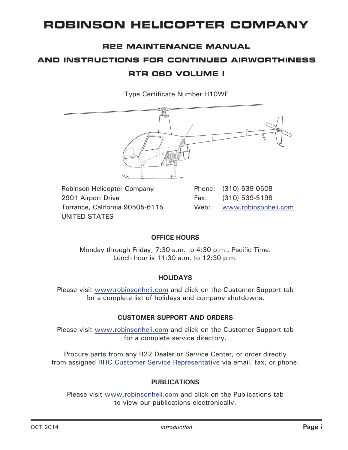
This is the complete Robinson Helicopter Company R22 Maintenance Manual and Instructions for Continued Airworthiness, publication RTR 060, Volume I, dated October 2014. Issued under FAA Type Certificate H10WE, this Robinson R22 Maintenance Manual is the primary reference for maintaining, servicing, and inspecting every version of the R22 built by Robinson Helicopter Company, from the earliest Standard/HP variants through the Alpha, Beta, Beta II, Mariner, and Mariner II configurations.
- Manual type: Maintenance Manual & Instructions for Continued Airworthiness (ICA)
- Brand/Model: Robinson R22 (Standard, HP, Alpha, Beta, Beta II, Mariner, Mariner II)
- Publication: RTR 060, Volume I
- Revision date: October 2014 (referenced Type Certificate Data Sheet Revision 15, August 15, 2013)
- Language: English
- Page count: 684 pages
- File format: PDF
Chapters Covered
- Chapter 1 – General: manual revisions, maintenance authorization, external dimensions, version descriptions, scheduled maintenance table, jacking/hoisting/leveling, weighing and CG calculation, fastener torque requirements, approved materials, part interchangeability
- Chapter 2 – Inspection: ball/roller bearings, push-pull tubes, 100-hour/annual inspection checklist, special inspections (hard landing, rotor/engine overspeed, tail rotor strike, lightning strike), 12-year inspection, 2200-hour overhaul requirements
- Chapter 3 – Life-Limited Components: time-in-service records, fatigue life-limited parts, Type Certificate Data Sheet, airworthiness limitations
- Chapter 4 – Airframe: cabin assembly, windshield, doors, fairings/cowlings, welded steel tube frame assemblies, tailcone and empennage
- Chapter 5 – Landing Gear: cross tubes, skid tubes, skid shoes, float ship landing gear
- Chapter 6 – Powerplant: engine removal/installation, cooling system, lubrication system, induction system, exhaust system, troubleshooting, carburetor heat assist
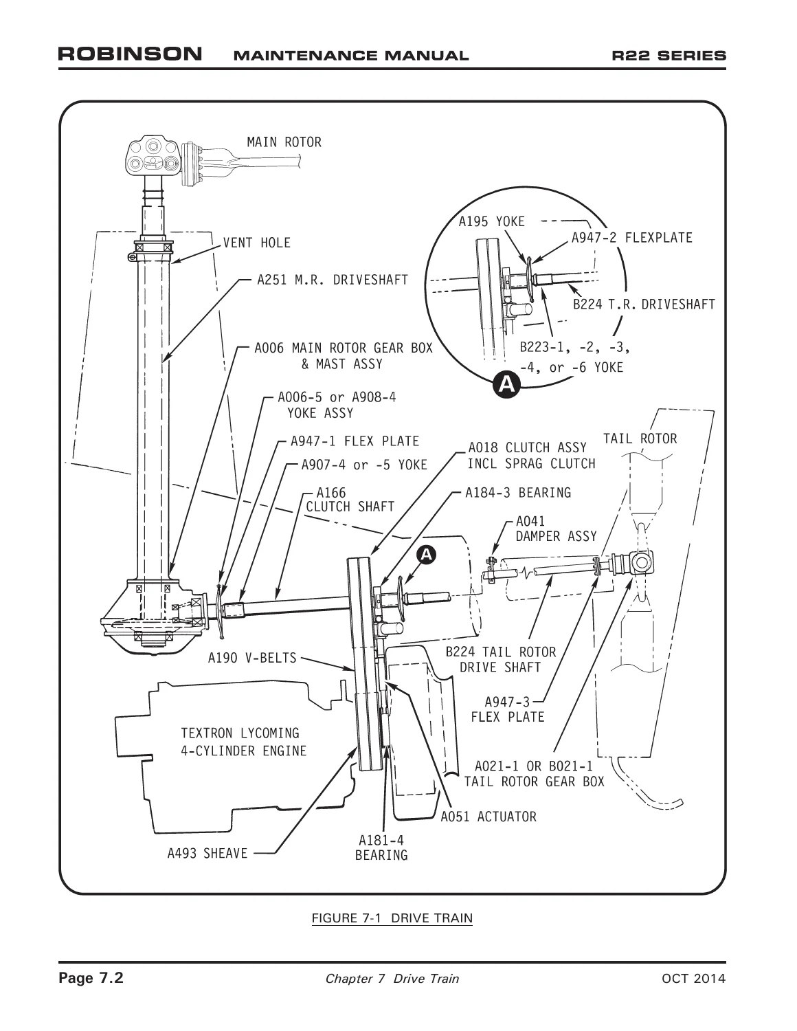
- Chapter 7 – Drive Train: main rotor gearbox, clutch assembly, V-belts, tail rotor drive shaft, tail rotor gearbox, actuator assembly, rotor brake
- Chapter 8 – Flight Controls: cyclic assembly, collective control, RPM governor system, jackshaft, swashplate, tail rotor controls and bellcranks
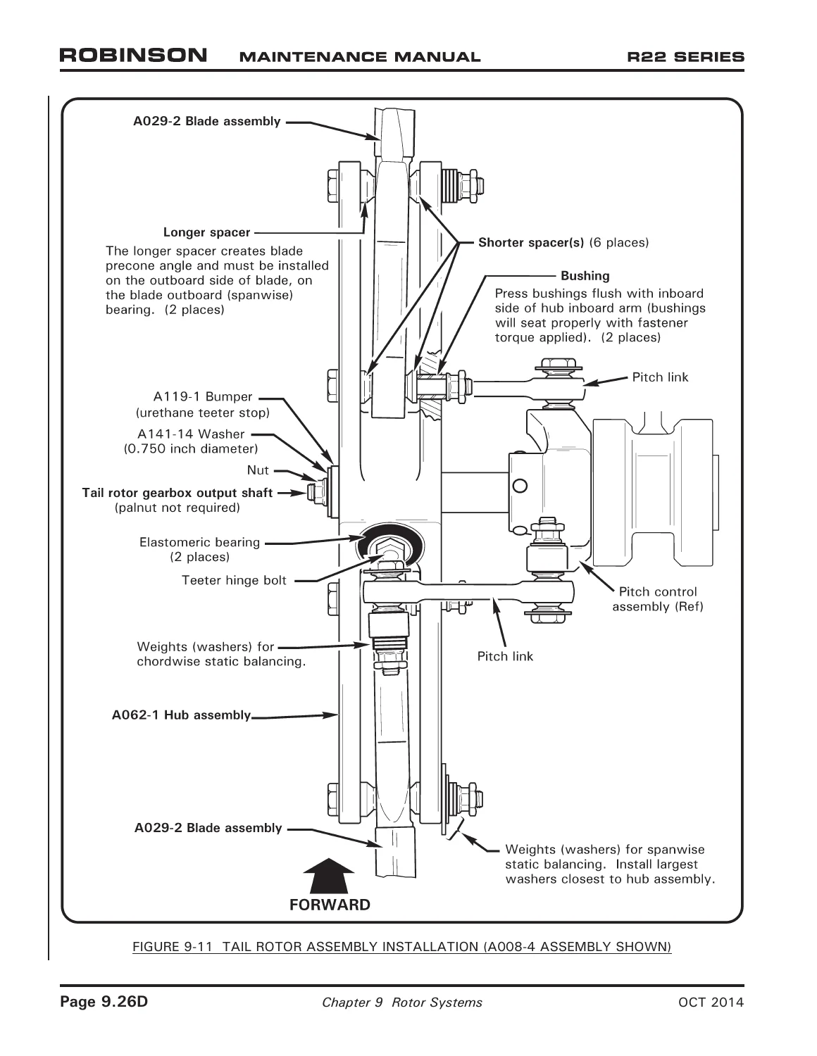
- Chapter 9 – Rotor Systems: main rotor blade inspection and repair limits, teeter and coning hinge, hub bearing replacement, tail rotor assembly installation
- Chapter 10 – Rigging, Track and Balance: main rotor blade trim tab adjustment
- Chapter 11 – Heating and Ventilation: cabin heater removal and installation
- Chapter 12 – Fuel System: fuel caps, fuel vents, fuel quantity sender and indication checks
- Chapter 13 – Instruments: pitot-static system, six-instrument console, Aspen PFD schematic
- Chapter 14 – Electrical and Avionics Systems: electrical system schematics, antenna locations, transponder, COM radio, audio control, and GPS schematics
- Chapter 15 – Furnishings
- Chapter 16 – Special Tools
- Chapter 17 – Revision Log
Complete PDF Bookmark Tree
Complete Bookmarks
The complete bookmarks in the “Robinson R22 Maintenance Manual & Instructions for Continued Airworthiness (RTR 060, October 2014)” are as follows:
+Introductionp. 1
Cover Pagep. 1
Subscription Order and Renewal Formp. 2
Chapter Listp. 3
Recommended Change Reportp. 4
Limited Aircraft Warrantyp. 5
Limited Parts Warrantyp. 6
Contentsp. 7
+Chapter 1 – Generalp. 21
+1.000 Introductionp. 23
1.001 R22 Maintenance Manual Revisionsp. 23
1.002 R22 Maintenance Authorizationp. 23
1.003 R22 Component Overhaul Authorizationp. 23
1.004 Maintenance Recordp. 24
1.005 Notationsp. 24
1.006 Definitions and Abbreviationsp. 25
1.007 Service Directoryp. 26
1.008 External Dimensionsp. 27
1.009 Version Descriptionp. 30
+1.100 Helicopter Servicingp. 33
1.101 Scheduled Maintenance and Inspectionsp. 33
1.105 Calibration of Toolsp. 33
1.110 Lubrication – Generalp. 33
1.115 Chip Detector Cleaningp. 34
1.120 Main Rotor Gearbox Drain And Flushp. 35
1.130 Tail Rotor Gearbox Drain And Flushp. 36
1.140 A184 Upper Bearing Lubricationp. 37
1.150 Defuelingp. 38
1.160 Storage (Greater than 30 days)p. 39
+1.200 Handling, Jacking, Hoisting, Leveling, and Weighingp. 41
+1.210 Ground Handlingp. 41
1.211 Ground Handling Wheelsp. 41
1.212 Ground Handling Wheels – Float Landing Gearp. 42
1.213 Moving the Helicopter on Ground Handling Wheelsp. 44
1.214 Main Rotor Blade Tie-Downsp. 44
1.215 Parkingp. 46
1.216 Traileringp. 46
1.220 Jacking, Hoisting, and Levelingp. 47
+1.230 Weighing and CG Calculationp. 50
1.231 Preparing Helicopter for Weighingp. 51
1.232 Weighing Procedure and Calculationsp. 51
1.240 Ballast Installationp. 55
+1.300 Fastener Torque Requirementsp. 57
+1.310 Generalp. 57
1.320 Standard Torquesp. 59
1.330 Special Torquesp. 60
+1.400 Approved MaterialsThe following items are availablep. 64
1.410 Paint Strippersp. 64
1.420 Solvents and Cleanersp. 64
1.430 Fillers and Puttyp. 65
1.440 Torque Sealp. 65
1.450 Primersp. 65
1.455 Powder Coatp. 65
1.460 Paintsp. 67
1.470 Lubricantsp. 69
1.480 Adhesives and Sealantsp. 70
1.490 Storage Limitsp. 72
1.500 Part Interchangeabilityp. 73
1.600 Instructions for Uncrating, Reassembling, and Flight Testing R22-series Helicoptersp. 74
1.700 Replacement Component Identification (Data) Platesp. 76
+Chapter 2 – Inspectionp. 77
2.000 Introductionp. 79
+2.100 General Proceduresp. 79
2.110 Ball and Roller Bearingsp. 79
+2.120 Push-Pull Tubes, Rod Ends, and Spherical Bearingsp. 79
2.121 Push-Pull Tubesp. 79
2.122 Rod Ends and Spherical Bearingsp. 80
2.125 Elastomeric Bearingsp. 82
2.130 Telatemp Indicatorsp. 84
+2.200 Ground and Flight Check for 100-Hour/Annual Inspectionp. 85
2.205 Ground Checkp. 85
2.210 Run Upp. 87
2.220 Flight Checkp. 88
2.300 Airframe Preparation for 100-Hour/Annual Inspectionp. 88
+2.400 100-Hour/Annual Airframe Inspectionp. 89
2.410 Inspection Procedures and Checklistp. 89
+2.500 Special Inspectionsp. 119
2.501 Clutch Actuator Upper and Lower Bearings Inspection and Lubricationp. 119
2.502 A181-4 Actuator Lower Bearing Inspection and Lubricationp. 119
2.503 A184 Actuator Upper Bearing Inspection and Lubricationp. 120
2.507 V-Belt Inspectionp. 121
2.508 Lower Sheave V-Belt Wear Pattern Inspectionp. 123
2.510 Tail Skid Strikep. 124
2.520 Tail Rotor Strikep. 125
2.530 Main Rotor Strikep. 126
2.540 Rotor/Engine Overspeedp. 127
2.550 Hard Landingp. 129
2.560 Steel Tube Frame Corrosionp. 131
+2.570 Main Rotor Blade Detail Inspectionp. 132
2.571 Spar Cover Adhesive Damagep. 132
2.572 Main Rotor Blade Sealant and Filler Crackingp. 134
2.573 Visual Inspection of Main Rotor Blade Root Areap. 135
2.580 Float Inspection and Testingp. 136
2.590 Windshield Inspectionp. 137
+2.600 12-Year Inspection and Limited Overhaul Requirementsp. 138
2.610 Inspection Procedurep. 138
2.620 Additional Parts Requiring Replacement on Some R22sp. 140
2.630 Component Inspection Procedurep. 141
+2.700 2200-Hour Overhaul Requirementsp. 142
2.710 Inspection Procedurep. 142
2.720 Additional Parts Requiring Replacement on Some R22sp. 144
+2.800 Additional Special Inspectionsp. 145
2.810 Volcanic Ash Recommendationsp. 145
2.820 Lightning Strikep. 146
+Chapter 3 – Life-Limited Componentsp. 147
+3.000 Life-Limited Componentsp. 149
3.001 Introductionp. 149
3.002 Time-In-Service Recordsp. 149
3.003 Fatigue Life-Limited Partsp. 149
+3.100 Inspection and Overhaul Requirementsp. 150
3.110 Powerplant Overhaul Requirementsp. 150
3.120 Aircraft Overhaul Requirementsp. 150
3.130 12-Year Inspection and Limited Overhaul Requirementsp. 150
3.140 Additional Bearing Replacement Requirementsp. 150
3.200 Type Certificate Data Sheet (TCDS)p. 150
3.300 Airworthiness Limitationsp. 161
+Chapter 4 – Airframep. 163
+4.000 Airframep. 165
4.001 Introductionp. 165
4.002 Descriptionp. 165
+4.100 Fuselagep. 165
4.110 Cabin Assemblyp. 165
+4.120 Windshield Assemblyp. 166
4.121 Windshield Removalp. 166
4.122 Windshield Installationp. 166
4.123 Windshield Replacementp. 167
4.130 Door Removal and Installationp. 168
+4.140 Fairing, Cowling and Inspection Panelsp. 168
4.141 Side Skirtsp. 168
4.142 Mast Fairingp. 170
4.143 Aft Cowlingp. 170
4.144 Cabin Inspection Panelsp. 170
+4.200 Welded Steel Tube Frame Assembliesp. 171
+4.210 Left-Hand Frame Assemblyp. 172
4.211 Left-Hand Frame Removalp. 172
4.212 Left-Hand Frame Installationp. 172
+4.220 Right-Hand Frame Assemblyp. 173
4.221 Right-Hand Frame Removalp. 173
4.222 Right-Hand Frame Installationp. 176
+4.230 Upper Frame Assemblyp. 177
4.231 Upper Frame Removalp. 177
4.232 Upper Frame Installationp. 178
4.240 Strut Assembly Removal and Installationp. 179
+4.300 Tailcone and Empennagep. 180
+4.310 Tailconep. 180
4.311 Tailcone Removalp. 180
4.312 Tailcone Installationp. 180
4.313 Tailcone Replacementp. 181
4.314 Tailcone Repairp. 186
+4.320 Empennage Assemblyp. 186
4.321 Empennage Removalp. 186
4.322 Empennage Installationp. 187
4.323 Upper Stabilizer Replacementp. 187
4.324 Lower Stabilizer Replacementp. 187
4.325 Horizontal Stabilizer Replacementp. 188
+Chapter 5 – Landing Gearp. 191
+5.000 Landing Gearp. 193
5.001 Introductionp. 193
5.002 Descriptionp. 193
+5.100 Landing Gear Assemblyp. 193
5.110 Landing Gear Removalp. 193
5.120 Landing Gear Installationp. 195
+5.200 Cross Tubesp. 195
5.210 Cross Tube Removalp. 195
5.220 Cross Tube Installationp. 198
+5.300 Skid Tubesp. 198
5.310 Skid Tube Removalp. 198
5.320 Skid Tube Installationp. 198
5.330 Skid Shoe Removal and Replacementp. 198
5.340 Ground Handling Wheel Support Removal and Replacementp. 200
5.400 Preventive Maintenancep. 200
+5.500 Float Ship Landing Gearp. 201
5.510 Float Landing Gear Removalp. 201
5.520 Float Landing Gear Installationp. 202
5.530 Float Tube Removalp. 203
5.540 Float Tube Installationp. 203
5.550 Float Tube Repairp. 205
+Chapter 6 – Powerplantp. 207
+6.000 Powerplant and Related Systemsp. 209
6.001 Introductionp. 209
6.002 Descriptionp. 209
+6.100 Powerplantp. 210
6.110 Engine Removalp. 210
6.120 Engine Installationp. 212
6.130 Engine Shimmingp. 214
+6.200 Cooling Systemp. 217
6.210 Fanwheel Removalp. 217
6.220 Fanwheel Installationp. 220
6.230 Reservedp. 221
6.240 Balancing Fanwheelp. 221
6.250 Cooling Scroll Replacementp. 225
+6.300 Lubrication Systemp. 230
6.310 Oil Cooler Removalp. 230
6.320 Oil Cooler Installationp. 230
+6.400 Induction Systemp. 230
6.410 Carburetor Removalp. 230
6.420 Air Box Removalp. 231
+6.430 Air Box Installationp. 231
6.435 Air Filter Cleaningp. 233
6.440 Carburetor Installationp. 233
6.450 Carburetor Heat Scoop Removalp. 234
6.460 Carburetor Heat Scoop Installationp. 234
+6.500 Exhaust Systemp. 234
6.510 Exhaust System Removalp. 234
6.520 Exhaust System Installationp. 234
+6.600 Troubleshootingp. 235
6.610 Low-Power Checklistp. 235
+6.700 Throttle Control and Carburetor Heat Assistp. 237
+6.710 Overtravel Springp. 237
6.711 Overtravel Spring Removalp. 237
6.712 Overtravel Spring Installationp. 237
6.720 Reservedp. 237
+6.730 Throttle Push-Pull Tube Assemblyp. 238
6.731 Throttle Push-Pull Tube Assembly Removalp. 238
6.732 Throttle Push-Pull Tube Assembly Installationp. 238
+6.740 Carburetor Heat Assistp. 238
6.741 Carburetor Heat Control Cable Removalp. 238
6.742 Carburetor Heat Control Cable Installationp. 239
6.743 D334-5 Carburetor Heat Assist Bellcrank Assembly Removalp. 239
6.744 D334-5 Carburetor Heat Assist Bellcrank Assembly Installationp. 239
6.745 D334-5 Bellcrank Friction Adjustmentp. 241
+Chapter 7 – Drive Trainp. 243
+7.000 Drive Trainp. 245
7.001 Introductionp. 245
7.002 Descriptionp. 245
+7.100 Main Rotor Gearboxp. 245
7.110 Main Rotor Gearbox Removalp. 245
7.120 Main Rotor Gearbox Installationp. 247
7.130 Leveling Main Rotor Gearboxp. 249
+7.140 A006-5/A908-4 Yoke Removal and Installationp. 251
7.141 Setting Hall Effect Sender Gapp. 251
+7.150 Replacement of Main Rotor Gearbox Pinion Sealp. 251
7.155 Replacement of Main Rotor Gearbox Sump O-Ringp. 253
7.160 Main Rotor Gearbox Overtemp Inspectionp. 254
7.170 Main Rotor Gearbox Chip Light Indicatorp. 255
7.180 Reservedp. 255
+7.200 Clutch Assemblyp. 256
+7.210 Clutch Assembly Removalp. 256
7.211 A184 Bearing Removalp. 258
7.212 A184 Bearing Installationp. 260
7.213 Clutch Assembly Seal Replacementp. 261
7.214 Clutch Assembly Lubricant Inspection and Servicingp. 262
7.220 Clutch Assembly Installationp. 265
7.230 Clutch Sheave Alignmentp. 268
7.240 Clutch Shaft Anglep. 270
7.250 Clutch Lateral Centeringp. 270
7.260 A907 Yoke Removal and Installationp. 272
7.270 A195 Yoke Removal and Installationp. 272
+7.280 V-Beltsp. 273
7.281 V-Belt Removalp. 273
7.282 V-Belt Installationp. 279
+7.290 A007-3 & -5 Fanshaft and Bearing Assembly, Starter Ring Gear Support,Lower Sheave and Alternator Belt Replacementp. 282
7.291 Removalp. 282
7.292 Installationp. 282
+7.300 Tail Rotor Drive Shaftp. 284
7.310 Tail Rotor Drive Shaft Removalp. 284
+7.320 Tail Rotor Drive Shaft Installationp. 285
7.321 Adjustment of Damper Frictionp. 287
7.330 Intermediate Flex Plate Installation and Shimmingp. 292
7.340 Checking Tail Rotor Drive Shaft Runoutp. 295
7.350 Two-Piece Tail Rotor Drive Shaftp. 297
7.360 B224-1 Tail Rotor Drive Shaft Corrosion Removalp. 300
+7.400 Tail Rotor Gearboxp. 301
7.410 Tail Rotor Gearbox Removalp. 301
7.420 Tail Rotor Gearbox Installationp. 301
7.430 Tail Rotor Gearbox Shimmingp. 302
7.440 Tail Rotor Gearbox Chip Indicatorp. 302
7.450 A021 Tail Rotor Gearbox Output Shaft Seal Replacementp. 303
7.460 B021 Tail Rotor Gearbox Output Shaft Seal Replacementp. 304
7.470 B021 Tail Rotor Gearbox Input Shaft Seal Replacementp. 306
+7.500 Actuator Assemblyp. 307
7.510 Actuator Removalp. 307
7.520 Actuator Installationp. 307
7.530 Actuator Gearmotor Replacementp. 307
7.540 Actuator Adjustmentp. 308
+7.550 Switch and Fuse Replacementp. 311
7.551 Switch Replacementp. 311
7.552 Fuse Replacementp. 311
+7.600 Rotor Brakep. 312
7.610 Rotor Brake Removalp. 312
7.620 Rotor Brake Installationp. 312
7.630 Rotor Brake Pad Replacementp. 313
+Chapter 8 – Flight Controlsp. 317
+8.000 Flight Controlsp. 321
8.001 Introductionp. 321
8.002 Descriptionp. 321
+8.100 Cyclic Controlsp. 321
+8.110 Cyclic Assemblyp. 321
8.111 Removal of Cyclic Assemblyp. 321
8.112 Installation of Cyclic Assemblyp. 324
+8.120 Cyclic Grip Assemblyp. 327
8.121 Removal of Cyclic Grip Assemblyp. 327
8.122 Installation of Cyclic Grip Assemblyp. 328
+8.130 Cyclic Lateral (Right) Trimp. 330
8.131 Right Trim Spring Assembly Removalp. 330
8.132 Right Trim Spring Assembly Installationp. 330
8.133 Right Trim Spring Replacement and Shimmingp. 331
+8.140 Selecting Longitudinal Elastic Trim Cordp. 335
8.141 Longitudinal Trim Cord Removalp. 339
8.142 Longitudinal Trim Cord Installationp. 339
+8.150 Cyclic Friction Assemblyp. 340
8.151 Cyclic Friction Adjustmentp. 340
+8.160 A121-7 Push-Pull Tubep. 341
8.161 A121-7 Push-Pull Tube Removalp. 341
8.162 A121-7 Push-Pull Tube Inspection/Repairp. 341
8.163 A121-7 Push-Pull Tube Sleeve Installationp. 342
8.164 A121-7 Push-Pull Tube Sleeve Inspectionp. 342
8.165 A121-7 Push-Pull Tube Installationp. 343
+8.200 Collective Controlp. 345
+8.210 Collective Stick Assemblyp. 345
8.211 Collective Stick Removalp. 345
8.212 Collective Stick Installationp. 346
+8.220 Collective Spring Assemblyp. 350
8.221 Collective Spring Removalp. 350
8.222 Collective Spring Installationp. 352
8.223 Collective Spring Adjustment for A038-1 thru -4 Assemblyp. 353
8.224 Collective Spring Adjustment for A038-5, -6, or -7 Assemblyp. 354
8.225 Collective Friction Adjustmentp. 354
+8.230 RPM Governor Systemp. 355
8.231 Governor Controller Removalp. 355
8.232 Governor Controller Installationp. 355
8.233 Governor Assembly Removalp. 355
8.234 Governor Assembly Installationp. 357
8.239 Governor Troubleshootingp. 357
+8.300 Jackshaft and Support Strutsp. 359
+8.310 Jackshaftp. 359
8.311 Jackshaft Removalp. 359
8.312 Jackshaft Installationp. 359
+8.320 Strut Assembly (Jackshaft Support)p. 359
8.321 Strut Removalp. 359
8.322 Strut Installationp. 362
+8.400 Swashplate and Main Rotor Pitch Linksp. 363
+8.410 Swashplatep. 363
8.411 Swashplate Removalp. 363
8.412 Swashplate Installationp. 364
8.413 Reservedp. 369
8.414 Reservedp. 369
8.415 Reservedp. 369
8.416 Shimming Upper (Unflanged) Spherical Sleeve with Aluminum Ballp. 372
+8.500 Tail Rotor Controlsp. 372
+8.510 Tail Rotor Pedalsp. 372
8.511 Tail Rotor Pedal Removalp. 372
8.512 Tail Rotor Pedal Installationp. 376
+8.520 A317-1 Lower Bellcrankp. 376
8.521 A317-1 Lower Forward Bellcrank Removalp. 376
8.522 A317-1 Lower Forward Bellcrank Installationp. 377
+8.530 A013-3 Upper Bellcrankp. 379
8.531 Bellcrank Removalp. 379
8.532 Bellcrank Installationp. 379
+8.540 A331-1 Intermediate Bellcrankp. 380
8.541 A331-1 Intermediate Bellcrank Rmovalp. 380
8.542 A331-1 Intermediate Bellcrank Installationp. 380
+8.550 A120-1 Aft Bellcrankp. 381
8.551 A120-1 Aft Bellcrank Removalp. 381
8.552 A120-1 Aft Bellcrank Installationp. 381
+8.560 A031 Pitch Controlp. 381
8.561 Pitch Control Removalp. 381
8.562 Pitch Control Installationp. 381
+8.570 Tail Rotor Pitch Linksp. 382
8.571 Tail Rotor Pitch Link Removalp. 382
8.572 Tail Rotor Pitch Link Installationp. 382
+8.600 A203 Yoke and A205 Fork Assembliesp. 384
+8.610 Bearing Removalp. 384
8.615 C648-2 Bearing Installationp. 384
8.620 A139-1 Bearing Installationp. 384
+8.630 B115-1 Bearing Installationp. 386
8.631 Interference-Fit Bearingsp. 386
8.632 Loctite-Secured Slip-Fit Bearingsp. 386
8.640 Yoke and Fork Assembly Installationp. 387
+Chapter 9 – Rotor Systemsp. 389
9.000 Rotor Systemsp. 391
+9.100 Main Rotorp. 391
+9.110 Main Rotor Bladesp. 391
9.111 Main Rotor Blade Removalp. 391
9.112 Main Rotor Blade Installationp. 394
9.113 Boot Removalp. 395
9.114 Boot Installationp. 395
9.115 Filling Pitch Bearing Housingp. 397
9.116 Drilling Main Rotor Hub Boltsp. 397
+9.120 Main Rotor Hubp. 398
9.121 Main Rotor Hub Removalp. 398
9.122 Main Rotor Hub Installationp. 398
9.123 Main Rotor Hub Journal and Shim Calculationsp. 401
9.124 Adjusting Hinge Frictionp. 404
9.125 Shifting the Main Rotor Hubp. 404
9.126 Main Rotor Hub Bearing Replacementp. 405
+9.130 Inspection of Main Rotor Bladesp. 407
9.131 Scratches and Corrosion on Blade Skins and Doublersp. 407
9.132 Dents and Local Deformationsp. 409
9.133 Root Fitting Damagep. 411
9.134 Voidsp. 413
+9.140 Repair of Main Rotor Bladesp. 415
9.141 Trimmingp. 417
9.142 Paintingp. 417
+9.200 Tail Rotorp. 419
+9.210 Tail Rotor Assembly Removalp. 419
9.212 Tail Rotor Installation with Spherical Teeter Bearingsp. 421
9.213 Tail Rotor Installation with Elastomeric Teeter Bearingsp. 424
9.214 Tail Rotor Hub Spherical Bearing Replacementp. 427
9.215 Tail Rotor Hub Elastomeric Bearing Replacementp. 428
9.220 Inspection and Repair of Tail Rotor Bladesp. 431
+Chapter 10 – Rigging, Track and Balancep. 435
+10.000 Rigging, Track and Balancep. 437
10.001 Introductionp. 437
10.002 Rod End Adjustment Procedures For Riggingp. 437
+10.100 Riggingp. 438
+10.110 Main Rotor Flight Controlsp. 438
10.111 Cyclic Controlsp. 438
10.112 Swashplatep. 439
10.113 Collective Controlp. 439
+10.120 Main Rotorp. 439
10.121 Cyclic Travel Riggingp. 444
10.122 Collective Travel Riggingp. 447
+10.130 Tail Rotor Flight Controlsp. 448
10.131 Pedalsp. 448
10.132 A316 Bellcrankp. 448
10.133 A331 Bellcrankp. 448
10.134 A120-1 Bellcrankp. 451
10.135 Tail Rotor Pitch Linksp. 451
10.140 Tail Rotor Riggingp. 451
10.150 Throttle Correlation Riggingp. 455
+10.200 Track and Balancep. 457
10.210 Equipment Requirementsp. 457
+10.220 Equipment Installationp. 458
10.221 Main Rotor Equipment Installationp. 458
10.222 Tail Rotor Equipment Installationp. 459
+10.230 Main Rotor Track and Balance Procedurep. 467
10.231 Main Rotor Balance Adjustmentsp. 468
10.232 Main Rotor Pitch Link Adjustmentp. 468
10.233 Main Rotor Blade Trim Tab Adjustmentp. 473
10.234 Main Rotor Track and Balance Troubleshootingp. 475
10.240 Tail Rotor Balance Procedurep. 477
10.250 Autorotational RPM Adjustmentp. 480
+Chapter 11 – Heating and Ventilationp. 483
+11.000 Heating and Ventilationp. 485
11.001 Introductionp. 485
11.002 Descriptionp. 485
+11.100 Cabin Heaterp. 485
11.110 Cabin Heater Removalp. 485
11.120 Cabin Heater Installationp. 486
+11.200 Ventilationp. 488
11.210 Cabin Air Vent Removalp. 488
11.220 Cabin Air Vent Installationp. 490
11.230 Door Ventp. 490
+Chapter 12 – Fuel Systemp. 491
12.000 Descriptionp. 493
+12.100 Fuel Tanksp. 495
12.110 Main Tankp. 495
12.120 Auxiliary Tankp. 499
+12.200 Fuel Ventsp. 503
12.210 (Vent Line) Rollover Valve Assembliesp. 503
12.300 Drain Valvesp. 503
+12.400 Fuel Quantityp. 505
12.410 Fuel Quantity Sendersp. 505
12.420 Fuel Quantity Indicationp. 506
12.430 Low-Fuel Switch Assemblyp. 507
12.500 Gascolator Assemblyp. 508
12.600 Minimum Fuel Flow Checkp. 509
+Chapter 13 – Instrumentsp. 511
13.000 Descriptionp. 513
13.100 Pitot-Static Systemp. 515
+13.200 Primary Instrumentsp. 516
13.210 Vertical Speed Indicatorp. 516
13.220 Airspeed Indicatorp. 516
13.230 Engine and Rotor Dual Tachometerp. 516
13.240 Altimeterp. 516
13.250 Manifold Pressure Gagep. 517
13.260 Magnetic Compassp. 517
+13.300 Engine Gagesp. 517
13.310 Ammeterp. 517
13.320 Engine Oil Pressure Gagep. 517
13.330 Engine Oil Temperature Gagep. 517
13.340 Cylinder Head Temperature Gagep. 517
13.350 Fuel Quantity Gagesp. 518
13.360 Carburetor Air Temperature Gagep. 518
+13.400 Additional Standard Indicating Equipmentp. 518
13.410 Clockp. 518
13.420 Outside Air Temperature (OAT) Gage/Voltmeterp. 518
13.430 Hourmeterp. 518
+13.500 Optional Equipmentp. 521
13.510 Aspen PFD Installationp. 521
13.600 Instrument Markingsp. 523
13.700 Troubleshootingp. 523
+Chapter 14 – Electrical and Avionics Systemsp. 525
+14.000 Electrical and Avionics Systemsp. 527
14.001 Introductionp. 527
14.002 Descriptionp. 527
14.100 Dual Tachometer Adjustmentp. 528
14.200 Low Rotor RPM Warning Unit Adjustmentp. 529
14.300 Alternator Output Voltage Adjustment Without A942-series ACUp. 529
+14.400 Troubleshootingp. 529
14.405 A569-5 Low Rotor RPM Warning Unitp. 529
14.410 Electrical Trouble-Shootingp. 532
14.420 Instrument Trouble-Shootingp. 534
14.430 Clutch Actuator Electrical Trouble-Shootingp. 535
14.440 Elctrically-Powered Instrument Calibration Valuesp. 536
14.500 Electrical Load Analysisp. 539
14.600 Electrical Systems Schematicsp. 542
14.700 Antenna Locationsp. 571
14.800 Avionics Schematicsp. 573
14.900 Upper Console Harness Plugsp. 607
+14.1000 IFR Trainerp. 609
14.1010 IFR Trainer Component Loadsp. 609
14.1020 IFR Trainer Console Accessp. 611
14.1030 IFR Trainer Component Locationp. 612
14.1040 IFR Trainer Avionics Schematicsp. 613
+14.1100 R22 Marinerp. 626
14.1110 R22 Mariner Avionics Schematicsp. 626
+14.1200 Avionics for R22 Helicopter S/N 4591, 4650, 4651, 4656 & Subsequentp. 633
14.1210 A024-9 Electrical System Installationp. 633
14.1220 A036-9 Electrical Components Installationp. 633
14.1230 A804-12 Transponder (Garmin GTX 330 ES) Installationp. 637
14.1240 C058-5 Cyclic Grip Assemblyp. 641
14.1250 C800-1 Aspen PFD Installationp. 641
14.1260 C802-2 COM Radio (Garmin GTR 225B) Installationp. 643
14.1270 C822-1 Audio Control (Garmin GMA 350H) Installationp. 647
14.1280 C831 GPS (Garmin GTN 600 series) Installationp. 651
+Chapter 15 – Furnishingsp. 655
+15.000 Furnishingsp. 657
15.001 Introductionp. 657
15.002 Descriptionp. 657
+15.100 Seat Beltp. 657
15.110 Seat Belt Removalp. 657
15.120 Seat Belt Installationp. 657
+15.200 Seat Assemblyp. 659
15.210 Seat Bottom Assembly Removal and Installationp. 659
15.220 Seat Back Assembly Removal and Installationp. 659
+15.300 Carpetp. 660
15.310 Carpet Removalp. 660
15.320 Carpet Installationp. 661
+15.400 Foam Installationp. 661
15.410 Foam Removalp. 661
15.420 Foam Installationp. 661
+15.500 Map Holder Pocketp. 662
15.510 Map Holder Removalp. 662
15.520 Map Holder Installationp. 662
+15.600 Fire Extinguisherp. 662
15.610 Fire Extinguisher Holder Removalp. 662
15.620 Fire Extinguisher Holder Installationp. 663
+15.700 License Holderp. 663
15.710 License Holder Removalp. 663
15.720 License Holder Installationp. 663
+15.800 Operator's Manual Strapp. 664
15.810 Strap Removalp. 664
15.820 Strap Installationp. 664
+Chapter 16 – Special Toolsp. 665
16.100 Special Toolsp. 667
16.200 Illustrations and Tasksp. 669
Chapter 17 – Revision Logp. 675
Together these chapters give a technician everything needed to service an R22 from routine 100-hour and annual inspections through major overhauls, drivetrain and rotor system work, and full electrical/avionics troubleshooting, all tied back to the FAA-certificated configurations detailed in the version description and Type Certificate Data Sheet sections.
Why This R22 Maintenance Manual Matters
This Robinson R22 Maintenance Manual and Instructions for Continued Airworthiness lets an owner, mechanic, or A&P technician perform the correct scheduled maintenance, special inspections, and component overhauls called out for R22-series helicopters, using the exact torque values, service limits, and procedures Robinson Helicopter Company specifies rather than guessing at generic figures. Because the R22 covers several distinct versions — Standard, HP, Alpha, Beta, Beta II, Mariner, and Mariner II — each with its own serial number range, engine, and gross weight, working from the correct factory Instructions for Continued Airworthiness is essential to keeping the aircraft airworthy and compliant. Delivery is instant: download the PDF immediately after purchase, no shipping and no waiting. It opens on any computer, tablet, or phone and can be printed in the hangar or shop as needed.
Reviews
There are no reviews yet.