Allison Transmission TS2470 WTEC II Electronic Controls Troubleshooting Manual – PDF DOWNLOAD
Original price was: $75.95.$28.95Current price is: $28.95.
Allison Transmission TS2470 WTEC II Electronic Controls Troubleshooting Manual – PDF DOWNLOAD
Description
Allison Transmission TS2470 WTEC II Electronic Controls Troubleshooting Manual – PDF DOWNLOAD
DESCRIPTION:
Allison Transmission TS2470 WTEC II Electronic Controls Troubleshooting Manual – PDF DOWNLOAD
Allison Transmission
MD/HD/B SERIES TRANSMISSIONS
Troubleshooting
Manual
1998 MAY
REV. 1 1999 OCTOBER
REV. 2 2004 JULY
REV. 3 2005 DECEMBER
TS2470EN
WTEC II Controls
(Pre-TransID and TID 1)
MD 3060/MD 3066/MD 3560(P)(R)
MD 3070PT
HD 4060/HD 4560(P)(R)
B 300/B 400/ B 500(P)(R)
This manual provides troubleshooting information for Allison Transmission (AT), MD/HD/B Series
Transmissions. Service Manuals SM2148EN and SM2457EN, and Parts Catalogs PC2150EN and PC2456EN may
be used in conjunction with this manual.
This manual includes:
•Description of the WTEC II electronic control system.
•Description of the electronic control system components.
•Description of diagnostic codes, system responses to faults, and troubleshooting.
•Wire, terminal, and connector repair information.
Specific instructions for using many of the available or required service tools and equipment are not included in
this manual. The service tool manufacturer will furnish instructions for using the tools or equipment.
Additional information may be published from time to time in Service Information Letters (SIL) and will be
included in future revisions of this and other manuals. Please use these SILs to obtain up-to-date information
concerning Allison Transmission products.
This publication is revised periodically to include improvements, new models, special tools, and procedures. A
revision is indicated by a letter suffix added to the publication number. Check with your Allison Transmission
service outlet for the currently applicable publication. Additional copies of this publication may be purchased from
authorized Allison Transmission service outlets.
TABLE OF CONTENTS:
Allison Transmission TS2470 WTEC II Electronic Controls Troubleshooting Manual – PDF DOWNLOAD
TS2470EN…………………………………………………………………………………………………………………………………………………………………………………… 1
TITLE PAGE……………………………………………………………………………………………………………………………………………………………………………… 2
FOREWORD — How to Use This Manual…………………………………………………………………………………………………………………………………………………………. 3
IMPORTANT SAFETY NOTICE………………………………………………………………………………………………………………………………………………………………….. 4
WARNINGS, CAUTIONS, AND NOTES…………………………………………………………………………………………………………………………………………………………….. 4
TRADEMARKS USED IN THIS MANUAL……………………………………………………………………………………………………………………………………………………………. 5
SHIFT SELECTOR TERMS AND DISPLAY INDICATIONS……………………………………………………………………………………………………………………………………………….. 5
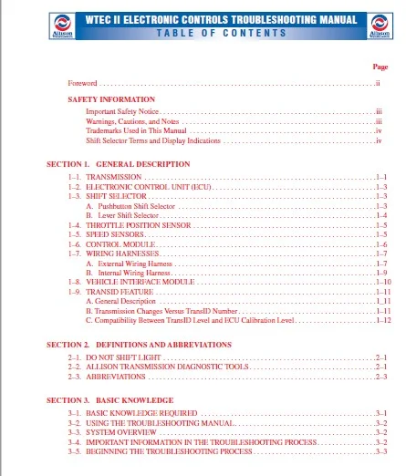
TABLE OF CONTENTS……………………………………………………………………………………………………………………………………………………………………….. 6
SECTION 1—GENERAL DESCRIPTION…………………………………………………………………………………………………………………………………………………………….. 10
1–1. TRANSMISSION……………………………………………………………………………………………………………………………………………………………………. 10
Figure 1–1. WTEC II Electronic Control Components (Units Produced Before 9/94)………………………………………………………………………………………………………….. 10
Figure 1–2. Electronic Control Unit Components (Units Produced 9/94–12/97)……………………………………………………………………………………………………………… 11
Figure 1–3. Electronic Control Unit Block Diagram……………………………………………………………………………………………………………………………………. 11
1–2. ELECTRONIC CONTROL UNIT (ECU)…………………………………………………………………………………………………………………………………………………….. 12
Figure 1–4. Electronic Control Unit (ECU)…………………………………………………………………………………………………………………………………………… 12
1–3. SHIFT SELECTOR………………………………………………………………………………………………………………………………………………………………….. 12
Figure 1–5. Pushbutton Shift Selectors……………………………………………………………………………………………………………………………………………… 13
Figure 1–6. Six-Speed And Seven-Speed Lever Shift Selectors…………………………………………………………………………………………………………………………… 13
1–4. THROTTLE POSITION SENSOR…………………………………………………………………………………………………………………………………………………………. 14
Figure 1–7. Throttle Position Sensor (TPS)………………………………………………………………………………………………………………………………………….. 14
1–5. SPEED SENSORS…………………………………………………………………………………………………………………………………………………………………… 14
Figure 1–8. Speed Sensors…………………………………………………………………………………………………………………………………………………………. 14
1–6. CONTROL MODULE………………………………………………………………………………………………………………………………………………………………….. 15
Figure 1–9. Control Module………………………………………………………………………………………………………………………………………………………… 16
1–7. WIRING HARNESSES………………………………………………………………………………………………………………………………………………………………… 16
Figure 1–10. WTEC II External Wiring Harness (Units Produced Before 9/94)………………………………………………………………………………………………………………. 17
Figure 1–11. WTEC II External Wiring Harness (Units Produced 9/94–12/97)……………………………………………………………………………………………………………….. 17
Figure 1–12. WTEC II Internal Wiring Harness (Units Produced Before 9/94)………………………………………………………………………………………………………………. 18
Figure 1–13. WTEC II Internal Wiring Harness (Units Produced 9/94–11/96)……………………………………………………………………………………………………………….. 18
Figure 1–14. WTEC II Internal Wiring Harness (Units Produced 11/96–12/97)………………………………………………………………………………………………………………. 19
1–8. VEHICLE INTERFACE MODULE…………………………………………………………………………………………………………………………………………………………. 19
Figure 1–15. Vehicle Interface Module (VIM)…………………………………………………………………………………………………………………………………………. 19
1–9. TRANSID FEATURE…………………………………………………………………………………………………………………………………………………………………. 20
Table 1–1. TransID 1 S/N Breakpoint………………………………………………………………………………………………………………………………………………… 21
Table 1–2. Software Level And TransID Compatibility………………………………………………………………………………………………………………………………….. 21
SECTION 2—DEFINITIONS AND ABBREVIATIONS……………………………………………………………………………………………………………………………………………………. 22
2–1. DO NOT SHIFT LIGHT………………………………………………………………………………………………………………………………………………………………. 22
2–2. ALLISON TRANSMISSION DIAGNOSTIC TOOLS……………………………………………………………………………………………………………………………………………… 22
Figure 2–1. Allison Transmission Diagnostic Tools……………………………………………………………………………………………………………………………………. 23
2–3. ABBREVIATIONS…………………………………………………………………………………………………………………………………………………………………… 24
SECTION 3—BASIC KNOWLEDGE………………………………………………………………………………………………………………………………………………………………… 28
3–1. BASIC KNOWLEDGE REQUIRED…………………………………………………………………………………………………………………………………………………………. 28
3–2. USING THE TROUBLESHOOTING MANUAL………………………………………………………………………………………………………………………………………………….. 29
3–3. SYSTEM OVERVIEW…………………………………………………………………………………………………………………………………………………………………. 29
3–4. IMPORTANT INFORMATION IN THE TROUBLESHOOTING PROCESS………………………………………………………………………………………………………………………………… 29
3–5. BEGINNING THE TROUBLESHOOTING PROCESS……………………………………………………………………………………………………………………………………………… 30
SECTION 4—WIRE TESTING PROCEDURES…………………………………………………………………………………………………………………………………………………………. 32
4–1. TESTING FOR OPENS, SHORTS BETWEEN WIRES, AND SHORTS-TO-GROUND………………………………………………………………………………………………………………………… 32
Figure 4–1. Open Circuit………………………………………………………………………………………………………………………………………………………….. 32
Figure 4–2. Short Between Wires and to Ground……………………………………………………………………………………………………………………………………….. 33
4–2. TESTING AT TRANSMISSION CONNECTOR AND THE INTERNAL HARNESS FOROPENS, SHORTS BETWEEN WIRES, AND SHORTS-TO-GROUND……………………………………………………………………………. 33
Figure 4–3. Feedthrough Connector, Seal, and Internal Harness…………………………………………………………………………………………………………………………. 34
Figure 4–4. Testing Continuity…………………………………………………………………………………………………………………………………………………….. 35
Figure 4–5. Short Between Wires and to Ground……………………………………………………………………………………………………………………………………….. 36
SECTION 5—OIL LEVEL SENSOR……………………………………………………………………………………………………………………………………………………………….. 38
5–1. ELECTRONIC FLUID LEVEL TEST (SHIFT SELECTOR)……………………………………………………………………………………………………………………………………….. 38
5–2. ELECTRONIC FLUID LEVEL TEST………………………………………………………………………………………………………………………………………………………. 41
SECTION 6—DIAGNOSTIC CODES……………………………………………………………………………………………………………………………………………………………….. 42
6–1. DIAGNOSTIC CODE MEMORY…………………………………………………………………………………………………………………………………………………………… 42
Table 6–1. Code List …………………………………………………………………………………………………………………………………………………………….. 42
6–2. CODE READING AND CODE CLEARING……………………………………………………………………………………………………………………………………………………. 42
6–3. DIAGNOSTIC CODE RESPONSE…………………………………………………………………………………………………………………………………………………………. 44
6–4. SHIFT SELECTOR DISPLAYS RELATED TO ACTIVE CODES…………………………………………………………………………………………………………………………………….. 44
6–5. DIAGNOSTIC CODE LIST AND DESCRIPTION………………………………………………………………………………………………………………………………………………. 45
Table 6–2. MD/HD/B Series Diagnostic Codes………………………………………………………………………………………………………………………………………….. 45
6–6. DIAGNOSTIC CODE TROUBLESHOOTING…………………………………………………………………………………………………………………………………………………… 58
Figure 6–1. Control Module Solenoid Location………………………………………………………………………………………………………………………………………… 59
CODE 13 XX—ECU INPUT VOLTAGE………………………………………………………………………………………………………………………………………………………….. 61
Figure 6–2. Code 13 Schematic Drawing………………………………………………………………………………………………………………………………………………. 61
CODE 14 XX—OIL LEVEL SENSOR…………………………………………………………………………………………………………………………………………………………… 64
Figure 6–3. Code 14 Schematic Drawing (Units Produced Before 9/94)…………………………………………………………………………………………………………………….. 64
Figure 6–4. Code 14 Schematic Drawing (Units Produced 9/94–12/97)……………………………………………………………………………………………………………………… 65
CODE 21 XX—THROTTLE POSITION SENSOR FAULT OR ADJUSTMENT………………………………………………………………………………………………………………………………….. 68
Figure 6–5. Code 21 Schematic Drawing (Units Produced Before 9/94)…………………………………………………………………………………………………………………….. 68
Figure 6–6. Code 21 Schematic Drawing (Units Produced 9/94–12/97)……………………………………………………………………………………………………………………… 69
CODE 22 XX—SPEED SENSOR/CIRCUITRY FAULT………………………………………………………………………………………………………………………………………………… 72
Figure 6–7. Code 22 Schematic Drawing (Units Produced Before 9/94)…………………………………………………………………………………………………………………….. 72
Figure 6–8. Code 22 Schematic Drawing (Units Produced 9/94–12/97)……………………………………………………………………………………………………………………… 73
CODE 23 XX—SHIFT SELECTOR…………………………………………………………………………………………………………………………………………………………….. 77
Figure 6–9. Code 23 Schematic Drawing………………………………………………………………………………………………………………………………………………. 77
CODE 24 XX—SUMP FLUID TEMPERATURE……………………………………………………………………………………………………………………………………………………… 80
Figure 6–10. Code 24 Schematic Drawing (Units Produced Before 9/94)……………………………………………………………………………………………………………………. 80
CODE 25 XX—OUTPUT SPEED SENSOR, DETECTED AT ZERO SPEED,X RANGE……………………………………………………………………………………………………………………………. 86
Figure 6–13. Code 25 Schematic Drawing (Units Produced Before 9/94)……………………………………………………………………………………………………………………. 86
CODE 32 XX—C3 PRESSURE SWITCH…………………………………………………………………………………………………………………………………………………………. 90
Figure 6–15. Code 32 Schematic Drawing (Units Produced Before 9/94)……………………………………………………………………………………………………………………. 90
CODE 33 XX—SUMP OIL TEMPERATURE SENSOR…………………………………………………………………………………………………………………………………………………. 94
Figure 6–17. Code 33 Schematic Drawing (Units Produced Before 9/94)……………………………………………………………………………………………………………………. 94
CODE 34 XX—EEPROM COMPATIBILITY OR CHECKSUM FAULT……………………………………………………………………………………………………………………………………….. 98
CODE 35 XX—POWER INTERRUPTION…………………………………………………………………………………………………………………………………………………………. 99
Figure 6–20. Code 35 Schematic Drawing……………………………………………………………………………………………………………………………………………… 99
CODE 36 XX—HARDWARE AND SOFTWARE NOT COMPATIBLE………………………………………………………………………………………………………………………………………….101
CODE 41 XX—OPEN OR SHORT-TO-GROUND IN SOLENOID CIRCUIT……………………………………………………………………………………………………………………………………102
Figure 6–21. Code 41 Schematic Drawing (Units Produced Before 9/94)………………………………………………………………………………………………………………………..102
CODE 42 XX—SHORT-TO-BATTERY IN SOLENOID CIRCUIT………………………………………………………………………………………………………………………………………….108
Figure 6–24. Code 42 Schematic Drawing (Units Produced Before 9/94)…………………………………………………………………………………………………………………….108
CODE 43 XX—SOLENOID LOW SIDE CIRCUIT, OPEN DRIVER,OR WIRE SHORTED-TO-GROUND…………………………………………………………………………………………………………………114
Figure 6–27. Code 43 Schematic Drawing (Units Produced Before 9/94)…………………………………………………………………………………………………………………….114
CODE 44 XX—SHORT-TO-GROUND IN SOLENOID CIRCUIT…………………………………………………………………………………………………………………………………………..118
Figure 6–29. Code 44 Schematic Drawing (Units Produced Before 9/94)…………………………………………………………………………………………………………………….118
CODE 45 XX—OPEN CONDITION IN SOLENOID CIRCUIT……………………………………………………………………………………………………………………………………………124
Figure 6–32. Code 45 Schematic Drawing (Units Produced Before 9/94)…………………………………………………………………………………………………………………….124
CODE 51 XX—OFFGOING RATIO TEST DURING SHIFT (TIE-UP TEST)…………………………………………………………………………………………………………………………………129
CODE 52 XX—OFFGOING C3 PRESSURE SWITCH TEST DURING SHIFT………………………………………………………………………………………………………………………………….131
CODE 53 XX—OFFGOING SPEED TEST (DURING SHIFT)……………………………………………………………………………………………………………………………………………133
CODE 54 XX—ONCOMING RATIO TEST (AFTER SHIFT)…………………………………………………………………………………………………………………………………………….135
CODE 55 XX—ONCOMING C3 PRESSURE SWITCH (AFTER SHIFT)……………………………………………………………………………………………………………………………………..137
CODE 56 XX—RANGE VERIFICATION RATIO TEST (BETWEEN SHIFTS)…………………………………………………………………………………………………………………………………139
CODE 57 XX—RANGE VERIFICATION C3 PRESSURE TEST(BETWEEN SHIFTS)…………………………………………………………………………………………………………………………….142
CODE 61 XX—RETARDER FLUID HOT………………………………………………………………………………………………………………………………………………………….143
CODE 62 XX—RETARDER TEMPERATURE SENSOR………………………………………………………………………………………………………………………………………………….146
Figure 6–36. Code 62 Schematic Drawing (Units Produced Before 9/94)…………………………………………………………………………………………………………………….146
CODE 63 XX—INPUT FUNCTION FAULT………………………………………………………………………………………………………………………………………………………..150
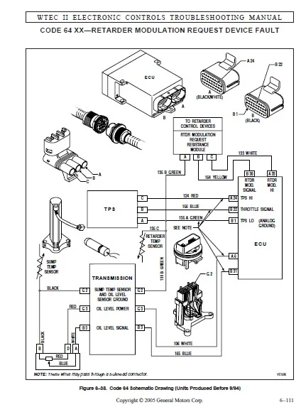
CODE 64 XX—RETARDER MODULATION REQUEST DEVICE FAULT………………………………………………………………………………………………………………………………………152
Figure 6–38. Code 64 Schematic Drawing (Units Produced Before 9/94)…………………………………………………………………………………………………………………….152
CODE 65 XX—ENGINE RATING HIGH………………………………………………………………………………………………………………………………………………………….158
CODE 66 XX—SCI (SERIAL COMMUNICATION INTERFACE) FAULT…………………………………………………………………………………………………………………………………….159
Figure 6–40. Code 66 Schematic Drawing………………………………………………………………………………………………………………………………………………159
CODE 69 XX—ECU MALFUNCTION…………………………………………………………………………………………………………………………………………………………….162
SECTION 7—INPUT AND OUTPUT FUNCTIONS……………………………………………………………………………………………………………………………………………………….164
A. INPUT FUNCTIONS……………………………………………………………………………………………………………………………………………………………………164
B. OUTPUT FUNCTIONS…………………………………………………………………………………………………………………………………………………………………..166
SECTION 8—GENERAL TROUBLESHOOTING OFPERFORMANCE COMPLAINTS……………………………………………………………………………………………………………………………………168
Table 8–1. Troubleshooting Performance Complaints………………………………………………………………………………………………………………………………………..169
Table 8–2. Resistance Module Troubleshooting Data………………………………………………………………………………………………………………………………………..184
APPENDICES (TABLE OF CONTENTS)…………………………………………………………………………………………………………………………………………………………….186
APPENDIX A—IDENTIFICATION OF POTENTIAL CIRCUIT PROBLEMS………………………………………………………………………………………………………………………………………188
APPENDIX B—TESTING CLUTCH PRESSURES………………………………………………………………………………………………………………………………………………………..190
APPENDIX C—SOLENOID AND CLUTCH CHART……………………………………………………………………………………………………………………………………………………….198
APPENDIX D—WIRE/CONNECTOR CHART……………………………………………………………………………………………………………………………………………………………200
Figure D–1. ECU Connector “A”………………………………………………………………………………………………………………………………………………………….201
Figure D–2. ECU Connector “B”………………………………………………………………………………………………………………………………………………………….202
Foldout D–1. Bulkhead Connector Cross-Reference Chart…………………………………………………………………………………………………………………………………….204
Figure D–3. 31-Way Deutsch IPD Bulkhead Connector………………………………………………………………………………………………………………………………………..205
Figure D–4. Deutsch Bulkhead Connector, ECD (Plug/Connector)………………………………………………………………………………………………………………………………206
Figure D–5. Cannon 37-Way FMTV Bulkhead Connector………………………………………………………………………………………………………………………………………..207
Figure D–6. Deutsch Transmission Connector, ECD (Plug/Connector)…………………………………………………………………………………………………………………………..208
Figure D–7. Transmission Connector (Before Model Year ’95)………………………………………………………………………………………………………………………………..209
Figure D–8. RSI Connector……………………………………………………………………………………………………………………………………………………………..210
Figure D–9. Optional Deutsch Sensor Harness Connector…………………………………………………………………………………………………………………………………….211
Figure D–10. Speed Sensor Connector…………………………………………………………………………………………………………………………………………………….212
Figure D–11. Diagnostic Connector………………………………………………………………………………………………………………………………………………………213
Figure D–12. Optional Deutsch Diagnostic Tool Connector…………………………………………………………………………………………………………………………………..214
Figure D–13. VIW (Amp) Connector……………………………………………………………………………………………………………………………………………………….215
Figure D–14. TPS Connector…………………………………………………………………………………………………………………………………………………………….216
Figure D–15. Transfer Case Connector……………………………………………………………………………………………………………………………………………………217
Figure D–16. Retarder Connector (MD/B 300/B 400)…………………………………………………………………………………………………………………………………………218
Figure D–17. Retarder Connector (HD/B 500)………………………………………………………………………………………………………………………………………………219
Figure D–18. Retarder Resistance Module/Interface Connector……………………………………………………………………………………………………………………………….220
Figure D–19. Retarder Temperature Sensor Connector (HD/B 500)……………………………………………………………………………………………………………………………..221
Foldout D–2. Customer-Furnished VIW/VIM Connector Cross-Reference Chart…………………………………………………………………………………………………………………….223
Figure D–20. VIM Connector (Harness)……………………………………………………………………………………………………………………………………………………224
Figure D–21. VIM Connector (Harness)……………………………………………………………………………………………………………………………………………………225
Figure D–22. Ford 16-Way Transmission Bulkhead Connector*…………………………………………………………………………………………………………………………………226
Figure D–23. Packard Metri-Pack VIM Connectors…………………………………………………………………………………………………………………………………………..227
Figure D–24. Packard Weather Pack VIM Connectors…………………………………………………………………………………………………………………………………………228
Figure D–25. Navistar Deutsch DT Series VIW Connector…………………………………………………………………………………………………………………………………….229
Figure D–26. Dill VIW Connectors……………………………………………………………………………………………………………………………………………………….231
Figure D–27. Packard Metri-Pack Cab And Chassis Harness Connectors…………………………………………………………………………………………………………………………233
Figure D–28. Resistance Module Type 2—Single Pressure Switch………………………………………………………………………………………………………………………………234
Figure D–29. Resistance Module Type 3—Bendix E-10R Pedal………………………………………………………………………………………………………………………………….235
Figure D–30. Resistance Module Type 5—Hand Lever…………………………………………………………………………………………………………………………………………236
Figure D–31. Resistance Module Type 7—Dedicated Pedal…………………………………………………………………………………………………………………………………….237
Figure D–32. Resistance Module Type 8—Three Pressure Switch……………………………………………………………………………………………………………………………….238
Figure D–33. Resistance Module Type 9—Two Pressure Switch…………………………………………………………………………………………………………………………………239
Figure D–34. End View of Oil Level Sensor Plug…………………………………………………………………………………………………………………………………………..240
APPENDIX E—CONNECTOR PART NUMBERS, TERMINAL PARTNUMBERS, TOOL PART NUMBERS, AND REPAIR INSTRUCTIONS……………………………………………………………………………………………….242
LIST OF SPECIAL TOOLS REQUIRED TO SERVICE WTEC II WIRING HARNESSES…………………………………………………………………………………………………………………………243
Figure E–1. Thomas & Betts ECU Connector, RSI Connector…………………………………………………………………………………………………………………………………..245
E–1. THOMAS & BETTS CONNECTORS (ECU AND RSI)…………………………………………………………………………………………………………………………………………….246
Figure E–2. Packard Metri-Pack 150 Series Connectors—Pull-to-Seat (Internal/External Harness to TransmissionFeedthrough; Speed Sensor; Accumulator Solenoid; 30-Way and 18-Way VIM)…………………….247
E–2. Packard Metri-Pack 150 Series connectors—Pull-to-Seat (Internal/External Harness toTransmission Feedthrough;Speed Sensor; Accumulator Solenoid; 30-Way and 18-Way VIM)……………………………248
Figure E–3A. Packard Metri-Pack 150 Series Connectors—Push-to-Seat (Former Oil Level Sensor)………………………………………………………………………………………………….251
E–3. PACKARD METRI-PACK 150 SERIES CONNECTORS—PUSH-TO-SEAT(FORMER OIL LEVEL SENSOR) (Figure E–3A)……………………………………………………………………………………………..252
Figure E–3B. Packard Metri-Pack 150 Series Connectors—Push-to-Seat (Current Oil Level Sensor)…………………………………………………………………………………………………255
E–3B. PACKARD METRI-PACK 150 SERIES CONNECTORS—PUSH-TO-SEAT(CURRENT OIL LEVEL SENSOR) (Figure E–3B)……………………………………………………………………………………………256
Figure E–4. Packard Metri-Pack 280 Series Connectors—Pull-to-Seat (8-Way Freightliner; 5-Way Navistar CabHarness; 2-Way Navistar and Ford Cab Harness; Internal Harness Solenoid and C3 Pressure Switch)….257
E–4. PACKARD METRI-PACK 280 SERIES CONNECTORS—PULL-TO-SEAT (8-WAYFREIGHTLINER; 5-WAY NAVISTAR CAB HARNESS; 2-WAY NAVISTAR ANDFORD CAB HARNESS; INTERNAL HARNESS SOLENOID AND C3 PRESSURESWITCH)………….258
Figure E–5. Packard Metri-Pack 280 Series Connectors—Push-to-Seat (Diagnostic Tool)………………………………………………………………………………………………………….261
E–5. PACKARD METRI-PACK 280 SERIES CONNECTORS—PUSH-TO-SEAT (DiagnosticTool Connector)………………………………………………………………………………………………………..262
Figure E–6. Packard Weather Pack Connectors (TPS; 3-Way RMR Sensor; HD Retarder Temperature; 6-Way Gillig VIM;4-Way RMR Device, Type 3; 3-Way RMR Device (Dedicated Pedal))……………………………265
E–6. PACKARD WEATHER PACK CONNECTORS (TPS; 3-WAY RMR SENSOR;HD RETARDER TEMPERATURE; 6-WAY GILLIG VIM; 4-WAY RMR DEVICE,TYPE 3; 3-WAY RMR DEVICE (DEDICATED PEDAL))…………………………………..266
Figure E–7. Terminal Crimping With Tool J 35606………………………………………………………………………………………………………………………………………….268
Figure E–8. Amp Products Connectors (16-Way VIW; 8-Way RMR Device (Hand Lever))……………………………………………………………………………………………………………..269
E–7. AMP PRODUCTS CONNECTORS (16-WAY VIW; 8-WAY RMR DEVICE(HAND LEVER))…………………………………………………………………………………………………………………….270
Figure E–9. Deutsch IPD/ECD Connectors (31-Way Bulkhead, 31-Way Feedthrough Harness;16-Way Optional Sensor Harness; 6-Way Optional Diagnostic Tool Connector)………………………………………..271
E–8. deutsch ipd……………………………………………………………………………………………………………………………………………………………………..272
Figure E–10. ITT Cannon Connectors—Crimped (37-Way FMTV Bulkhead; 6-Way Transfer Case; 8-Way MD Retarder)………………………………………………………………………………………275
E–9. ITT Cannon Connectors—Crimped (37-Way FMTV Bulkhead;6-Way Transfer Case; 8-Way MD Retarder)………………………………………………………………………………………………276
Figure E–11. ITT Cannon Connectors—Soldered (2-Way HD Retarder)……………………………………………………………………………………………………………………………279
E–10. ITT CANNON CONNECTORS—SOLDERED (2-WAY HD RETARDER)………………………………………………………………………………………………………………………………….280
Figure E–12. Deutsch DT Series Connectors (12-Way Navistar VIW)……………………………………………………………………………………………………………………………283
E–11. Deutsch DT Series Connectors (12-way navistar viw)………………………………………………………………………………………………………………………………….284
Figure E–13. Dill Connectors (Freightliner 4-Way Fuse and 5-Way Relay VIW)………………………………………………………………………………………………………………….287
E–12. DILL CONNECTORS (FREIGHTLINER 4-WAY FUSE AND 5-WAY RELAY VIW)………………………………………………………………………………………………………………………..288
Figure E–14. EPC Connectors (Ford 16-Way Bulkhead)……………………………………………………………………………………………………………………………………….291
E–13. EPC Connectors (Ford 16-Way Bulkhead)……………………………………………………………………………………………………………………………………………..292
E–14. REPAIR OF A BROKEN WIRE WITH IN-LINE BUTT SPLICE……………………………………………………………………………………………………………………………………293
Figure E–15. Crimper J 38125-8…………………………………………………………………………………………………………………………………………………………293
Figure E–16. Deutsch IPD/ECD Connectors (31-Way Bulkhead, 31-Way Feedthrough Harness; 16-Way Optional SensorHarness; 6-Way Optional Diagnostic Tool Connector)……………………………………….295
E–15. deutsch ecd connectors (31-way bulkhead; 31-way feedthrough harness; 16-way optionalsensor harness; 6-way optional DIAGNOSTIC TOOL CONNECTOR)…………………………………………………296
Figure E–17. Delphi-Packard (DHD) Connectors (31-Way); Crimping Tool……………………………………………………………………………………………………………………….301
E–16. DELPHI-PACKARD (DHD) 31-WAY CONNECTOR……………………………………………………………………………………………………………………………………………..302
Figure E–18. Pin and Socket Extraction………………………………………………………………………………………………………………………………………………….302
Figure E–19. Pin and Socket Insertion…………………………………………………………………………………………………………………………………………………..304
Figure E–20. Auxiliary Seal Orientation…………………………………………………………………………………………………………………………………………………305
E–17. LIST OF MD/HD/B SERIES TRANSMISSION CONNECTOR PARTS…………………………………………………………………………………………………………………………………306
APPENDIX F—THROTTLE POSITION SENSOR ADJUSTMENT………………………………………………………………………………………………………………………………………………324
A. Description of Operation……………………………………………………………………………………………………………………………………………………………324
Figure F–1. Throttle Position to Voltage Conversion…………………………………………………………………………………………………………………………………..324
Figure F–2. Throttle Position Determination Diagram…………………………………………………………………………………………………………………………………..324
B. Throttle Position Sensor (TPS) Adjustment…………………………………………………………………………………………………………………………………………….326
Table F–1. Volts Versus Count for Throttle Sensor Display Reading………………………………………………………………………………………………………………………327
Figure F–3. Throttle Position Sensor Adjustment………………………………………………………………………………………………………………………………………329
APPENDIX G—MISCELLANEOUS ITEMS…………………………………………………………………………………………………………………………………………………………….330
A. WELDING ON VEHICLE…………………………………………………………………………………………………………………………………………………………………330
B. VEHICLE INTERFACE MODULE……………………………………………………………………………………………………………………………………………………………330
Figure G–1. Vehicle Interface Module (VIM)…………………………………………………………………………………………………………………………………………..330
Figure G–2. VIM Components Location and Pin-Out Diagram……………………………………………………………………………………………………………………………….331
APPENDIX H—HYDRAULIC SCHEMATICS……………………………………………………………………………………………………………………………………………………………332
Figure H–1. C2 Latch Valve Detail………………………………………………………………………………………………………………………………………………………332
Figure H–2. Hydraulic Schematic—Neutral…………………………………………………………………………………………………………………………………………………333
Figure H–3. Hydraulic Schematic—Reverse…………………………………………………………………………………………………………………………………………………334
Figure H–4. Hydraulic Schematic—1st Range……………………………………………………………………………………………………………………………………………….335
Figure H–5. Hydraulic Schematic—2nd Range……………………………………………………………………………………………………………………………………………….336
Figure H–6. Hydraulic Schematic—3rd Range……………………………………………………………………………………………………………………………………………….337
Figure H–7. Hydraulic Schematic—4th Range……………………………………………………………………………………………………………………………………………….338
Figure H–8. Hydraulic Schematic—5th Range……………………………………………………………………………………………………………………………………………….339
Figure H–9. Hydraulic Schematic—6th Range……………………………………………………………………………………………………………………………………………….340
Figure H–10. MD 3070 Hydraulic Schematic—Neutral, Power On………………………………………………………………………………………………………………………………..341
Figure H–11. MD 3070 Hydraulic Schematic— Reverse, Power On……………………………………………………………………………………………………………………………….342
Figure H–12. MD 3070 Hydraulic Schematic—Lo MD, Power On………………………………………………………………………………………………………………………………….343
Figure H–13. MD 3070 Hydraulic Schematic— 1st, Power On…………………………………………………………………………………………………………………………………..344
Figure H–14. MD 3070 Hydraulic Schematic—2nd, Power On……………………………………………………………………………………………………………………………………345
Figure H–15. MD 3070 Hydraulic Schematic—3rd, Power On……………………………………………………………………………………………………………………………………346
Figure H–16. MD 3070 Hydraulic Schematic—4th, Power On……………………………………………………………………………………………………………………………………347
Figure H–17. MD 3070 Hydraulic Schematic—5th, Power On……………………………………………………………………………………………………………………………………348
Figure H–18. MD 3070 Hydraulic Schematic—6th, Power On……………………………………………………………………………………………………………………………………349
Figure H–19. MD/B 300/B 400 Retarder Hydraulic Schematic, Retarder On (Before S/N 6510021203)…………………………………………………………………………………………………350
Figure H–20. MD/B 300/B 400 Retarder Hydraulic Schematic, Retarder Off (Before S/N 6510021203)………………………………………………………………………………………………..351
Figure H–21. MD/B 300/B 400 Retarder Hydraulic Schematic, Retarder On (From S/N 6510021203 to December 31, 1997)………………………………………………………………………………..352
Figure H–22. MD/B 300/B 400 Retarder Hydraulic Schematic, Retarder Off(From S/N 6510021203 to December 31, 1997)………………………………………………………………………………..353
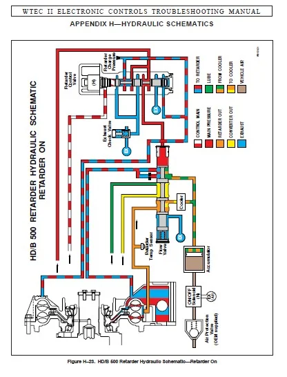
Figure H–23. HD/B 500 Retarder Hydraulic Schematic—Retarder On…………………………………………………………………………………………………………………………….354
Figure H–24. HD/B 500 Retarder Hydraulic Schematic—Retarder Off……………………………………………………………………………………………………………………………355
APPENDIX J—MD/HD/B SERIES TRANSMISSION WIRING SCHEMATICS……………………………………………………………………………………………………………………………………..357
Foldout J–1. MD/HD/B Wiring Schematic (Pre-TransID)………………………………………………………………………………………………………………………………………357
Foldout J–2. WTEC II TransID 1 Wiring Schematic (Began September, 1996)…………………………………………………………………………………………………………………….358
APPENDIX K—SOLENOID AND TEMPERATURE CHARTS………………………………………………………………………………………………………………………………………………….359
Figure K–1. Temperature Sensor Chart……………………………………………………………………………………………………………………………………………………359
Figure K–2. Solenoid Resistance vs.Temperature Chart……………………………………………………………………………………………………………………………………..360
APPENDIX L—EXTERNALLY-GENERATED ELECTRONIC INTERFERENCE………………………………………………………………………………………………………………………………………361
1–1. ELECTROMAGNETIC/RADIO FREQUENCY INTERFERENCE (EMI/RFI)……………………………………………………………………………………………………………………………….361
1–2. GENERAL GUIDELINES FOR RADIO EQUIPMENT INSTALLATION………………………………………………………………………………………………………………………………….361
1–3. EXTERNALLY-GENERATED SPEED SENSOR SIGNALS…………………………………………………………………………………………………………………………………………..362
APPENDIX M—DIAGNOSTIC TREE FOR MD/HD/B SERIES……………………………………………………………………………………………………………………………………………….363
Figure M–1. Diagnostic Tree—MD/HD/B Series Hydraulic System With Gauges…………………………………………………………………………………………………………………….363
Figure M–2. Diagnostic Tree—MD/HD/B Series Hydraulic System Without Gauges………………………………………………………………………………………………………………….364
APPENDIX N—DIAGNOSTIC TOOL INFORMATION……………………………………………………………………………………………………………………………………………………..365
APPENDIX P—INPUT/OUTPUT FUNCTIONS………………………………………………………………………………………………………………………………………………………….367
Figure P–1. Secondary Shift Schedule……………………………………………………………………………………………………………………………………………………367
Figure P–2. D1 Selection………………………………………………………………………………………………………………………………………………………………368
Figure P–3. PTO Enable (Using “PTO” Switch)……………………………………………………………………………………………………………………………………………..369
Figure P–4. PTO Enable (Using “MODE” Button)…………………………………………………………………………………………………………………………………………….370
Figure P–5. Shift Selector Transition…………………………………………………………………………………………………………………………………………………..371
Figure P–6. Auxiliary Function Range Inhibit (Standard)…………………………………………………………………………………………………………………………………..372
Figure P–7. Auxiliary Function Range Inhibit (Special)……………………………………………………………………………………………………………………………………373
Figure P–8. Auxiliary Hold…………………………………………………………………………………………………………………………………………………………….374
Figure P–9. Engine Brake/Preselect Request and Engine Brake Enable (Standard)……………………………………………………………………………………………………………….375
Figure P–10. Engine Brake/Preselect Request and Engine Brake Enable (European)………………………………………………………………………………………………………………376
Figure P–11. Fire Truck Pump Mode………………………………………………………………………………………………………………………………………………………377
Figure P–12. Fire Truck Pump Mode (Optional)…………………………………………………………………………………………………………………………………………….378
Figure P–13. Quick-To-Neutral Pump……………………………………………………………………………………………………………………………………………………..379
Figure P–14. Automatic Neutral for PTO (Standard)………………………………………………………………………………………………………………………………………..380
Figure P–15. Automatic Neutral for PTO (Special)…………………………………………………………………………………………………………………………………………381
Figure P–16. Automatic Neutral…………………………………………………………………………………………………………………………………………………………382
Figure P–17. Two Speed Axle Input and Output…………………………………………………………………………………………………………………………………………….383
Figure P–18. Manual Lockup…………………………………………………………………………………………………………………………………………………………….384
Figure P–19. Reverse Enable……………………………………………………………………………………………………………………………………………………………385
Figure P–20. Shift in Process/Shift Enable………………………………………………………………………………………………………………………………………………386
Figure P–21. Anti-Lock Brake Response…………………………………………………………………………………………………………………………………………………..387
Figure P–22. Retarder Enable…………………………………………………………………………………………………………………………………………………………..388
SERVICE BRAKE STATUS………………………………………………………………………………………………………………………………………………………………….389
Figure P–23. Differential Clutch Request………………………………………………………………………………………………………………………………………………..390
Figure P–24. Automatic Neutral for Refuse Packer and PTO Enable……………………………………………………………………………………………………………………………391
Figure P–25. Automatic Neutral for Refuse Packer and PTO Enable (Optional)………………………………………………………………………………………………………………….392
Figure P–26. Kickdown…………………………………………………………………………………………………………………………………………………………………393
Figure P–27. Fourth Lockup Pump Mode……………………………………………………………………………………………………………………………………………………394
Figure P–28. Automatic Neutral for Refuse Packer and PTO Enable With Service Brake Status…………………………………………………………………………………………………….395
Figure P–29. Automatic Neutral for Refuse Packer and PTO Enable With Service Brake Status (Option 1)…………………………………………………………………………………………..396
Figure P–30. Sump/Retarder Temperature Indicator…………………………………………………………………………………………………………………………………………397
Figure P–31. Range Indicator…………………………………………………………………………………………………………………………………………………………..398
Figure P–32. Output Speed Indicator—A…………………………………………………………………………………………………………………………………………………..399
Figure P–33. Output Speed Indicator—B…………………………………………………………………………………………………………………………………………………..400
Figure P–34. PTO Overspeed Indicator……………………………………………………………………………………………………………………………………………………401
Figure P–35. Engine Overspeed Indicator…………………………………………………………………………………………………………………………………………………402
Figure P–36. Lockup Indicator………………………………………………………………………………………………………………………………………………………….403
Figure P–37. Secondary Mode Indicator…………………………………………………………………………………………………………………………………………………..404
RETARDER INDICATOR……………………………………………………………………………………………………………………………………………………………………405
Figure P–38. Neutral Indicator for PTO and PTO Enable…………………………………………………………………………………………………………………………………….406
IMAGES PREVIEW OF THE MANUAL:
ALLISON TRANSMISSION TS2470 WTEC II ELECTRONIC CONTROLS TROUBLESHOOTING MANUAL – PDF DOWNLOAD:
PLEASE NOTE:
- This is the same manual used by the dealers to diagnose and troubleshoot your vehicle
- You will be directed to the download page as soon as the purchase is completed. The whole payment and downloading process will take anywhere between 2-5 minutes
- Need any other service / repair / parts manual, please feel free to contact [email protected] . We still have 50,000 manuals unlisted
S.V