
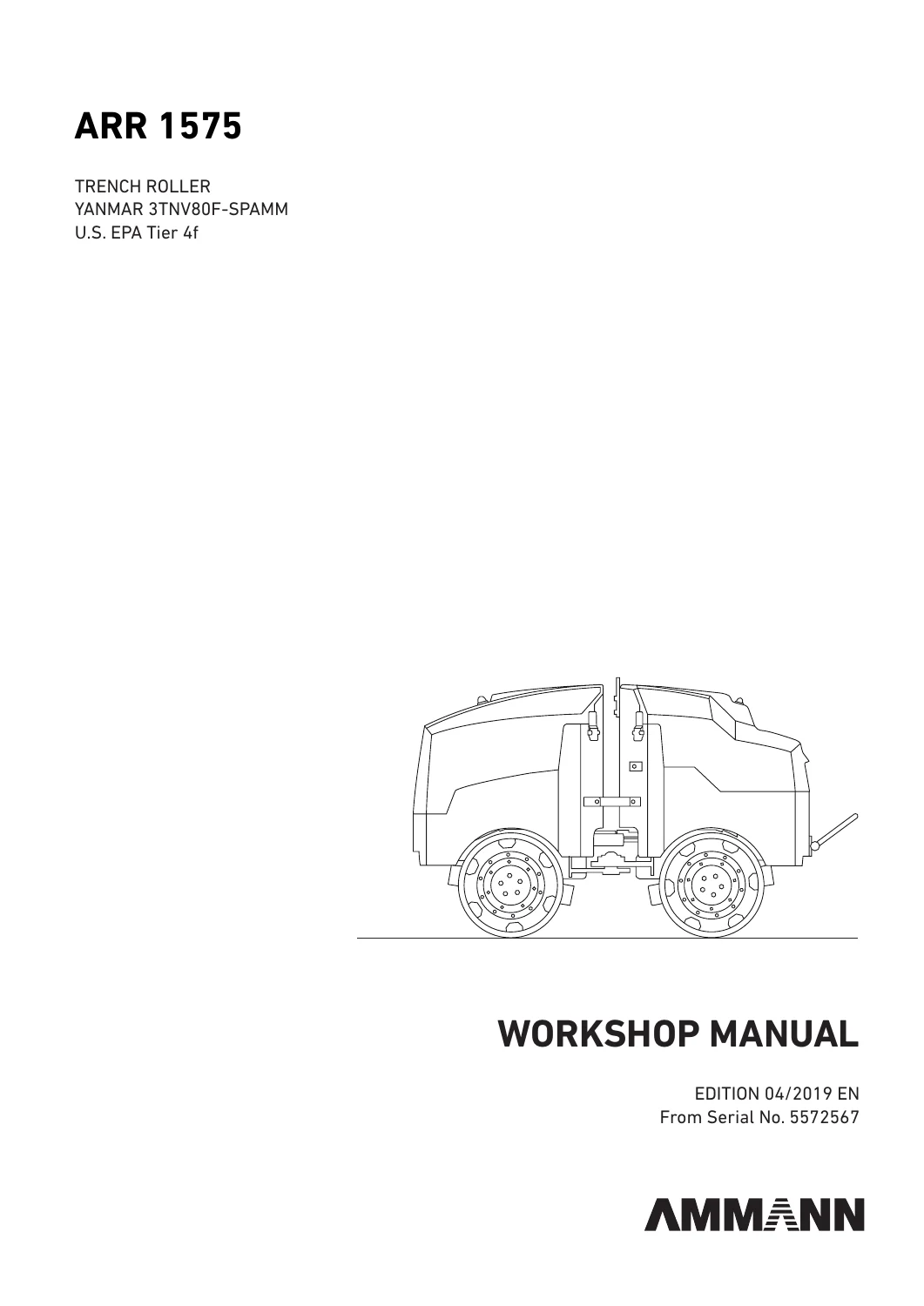
Ammann ARR 1575 Trench Roller Workshop Service Manual (From Serial No. 5572567)
Original price was: $39.95.$24.95Current price is: $24.95.
Comprehensive workshop manual for the Ammann ARR 1575 Trench Roller equipped with the Yanmar 3TNV80F-SPAMM Tier 4 Final engine, applicable from serial number 5572567. Covers complete machine disassembly, assembly, hydraulic circuit diagnostics, infrared remote control calibration, electrical troubleshooting, and workshop repair procedures across 346 pages.
Description
The Ammann ARR 1575 Trench Roller Workshop Service Manual (From Serial No. 5572567) provides comprehensive service guidance for the mechanical overhaul, hydraulic system testing, and electrical diagnostics of the Ammann ARR 1575 articulated trench roller. Designed specifically for compaction equipment operating in demanding utility trenches, civil excavations, and wet clay foundations, this comprehensive 346-page service publication delivers full step-by-step repair methodologies supported by photographic sequences, assembly jigs, detailed circuit schematics, and manufacturer calibration data. Technicians servicing machines powered by the liquid-cooled Yanmar 3TNV80F-SPAMM engine will find exhaustive technical specifications, exact torque benchmarks, and systematic troubleshooting routines covering every primary machine subassembly.
File Details
- Manual Type: Workshop Manual
- Brand: Ammann
- Equipment Model: ARR 1575 Trench Roller (U.S. EPA Tier 4f / ARR 1575 T4 final)
- Applicable Serial Numbers: From Serial No. 5572567
- Engine Model: Yanmar 3TNV80F-SPAMM 3-Cylinder Liquid-Cooled Diesel Engine
- Document Publication / Book ID: 4-P08000-EN
- Edition / Revision: Edition 04/2019 EN
- Language: English
- Page Count: 346 pages
- File Format: PDF (Digital Download)
Chapters Covered
- 1 Introduction: Scope of service publication, subassembly identification, spare parts coordination, cleanliness standards, and general assembly guidelines.
- 2 Safety Measures and Instructions: General safety rules, repair safety principles, high-pressure hydraulic safety, electrical safety, welding precautions, environmental standards, and warranty liability rules.
- 3 Machine Description: Application specifications, CE designation nameplate layouts, dimensional line drawings, and comprehensive technical data tables.
- 4 Specification of Operating Fluids: Engine oil viscosity charts, fuel requirements and biodiesel limitations, cooling mixture standards, ISO VG 46 HVLP hydraulic oil criteria, and fluid capacity charts.
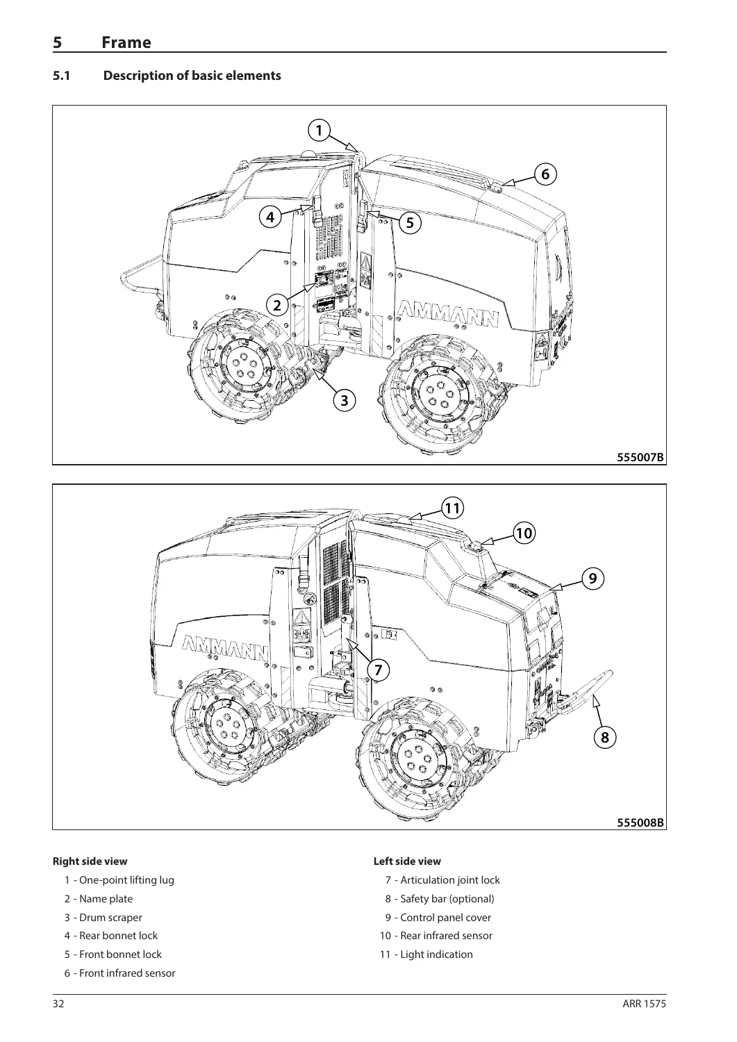
- 5 Frame: Exterior component layout, swinging support and joint head replacement, swinging joint bearing renewal, steering piston removal, front and rear bonnet assembly, gas strut service, fuel tank cleaning, and hydraulic tank maintenance.
- 6 Cab and Platform: Control console components, display unit warning indicators, infrared light emitter layout, automatic remote pairing routines, safe operating angles, wire harness wiring lists, remote battery renewal, and central control unit replacement.
- 7 Front Drum: Hydraulic hose schematics, valve block distribution, drum extension removal, drum removal, vibration unit rubber mounts, vibration unit overhaul, travel motor replacement, vibration motor replacement, and scraper alignment.
- 8 Rear Drum: Hydraulic circuit routing, drum assembly removal, ACEecon compaction measurement sensor disassembly and installation, and mechanical scraper adjustments.
- 9 Front Axle: Axle configuration reference (not included in machine equipment).
- 10 Rear Axle: Axle configuration reference (not included in machine equipment).
- 11 Travel: Travel drive pump replacement, vibration travel pump fitting torques, travel valve block overhaul, solenoid valve resistance testing, brake functional testing, and travel motor renewal.
- 12 Vibration: Vibration drive circuits, dual-amplitude operation, and hydraulic vibration motor integration.
- 13 Steering: Articulated joint steering geometry, steering cylinder lines, and steering hydraulic piston replacement.
- 14 Cooling: Hydraulic oil cooler maintenance, radiator fin cleaning, coolant replenishment, and expansion vessel inspection.
- 15 Engine: Engine compartment overview, electrical relays and fuse assignments, starter and alternator service, water separator cleaning, fuel filter element renewal, engine oil draining, and air filter maintenance.
- 16 Optional Equipment: Optional equipment directory, safety bar replacement, safety proximity sensor replacement, and alignment procedures.
- 17 General Procedures: Electrical system isolation, anti-burn welding precautions, auxiliary battery jump-starting, battery bench charging, and long-term storage preservation.
- 18 Troubleshooting: Comprehensive electrical fault diagnosis, engine starting failure matrices, infrared signal and conductor test procedures, safe operating zones, hydraulic pressure checks, travel pump servo block inspection, quantity divider testing, and roller overturning recovery protocols.
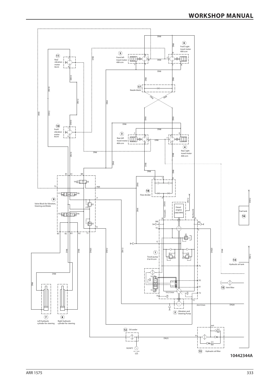
- 19 Appendices: Travel pump zero-position adjustment, complete multi-page electrical wiring diagram, comprehensive hydraulic system schematic, workshop jigs and special puller tools, and general threaded fastener torque tables.
This systematic chapter arrangement equips field mechanics, fleet service managers, and workshop technicians with a structured reference covering every physical assembly and hydraulic circuit on the machine. Rather than offering superficial maintenance checklists, this document provides the granular disassembly steps, mechanical tolerances, and circuit pressures required to overhaul major aggregates to original Ammann performance standards.
Frame, Articulated Swinging Joint & Chassis Servicing
The central oscillation and steering section is critical to the machine compaction efficiency and lateral stability. This manual provides exhaustive technical procedures for inspecting, removing, and servicing the center swinging support and the main articulated swinging joint. Step-by-step instructions guide technicians through securing the front and rear frames with locking pins, unloading chassis stress using hydraulic floor jacks, and measuring axial bearing clearance (mandating replacement when axial play exceeds 4 mm). The manual details the fabrication and use of specialized bearing puller tools, the extraction of heavy clamping pins under workshop presses, and precise reassembly requiring red and blue thread adhesives, spherical bearing lubrication, and final joint bolt torquing up to 210 Nm.
Hydrostatic Travel Drive & Hydraulic System Overhaul
Operating a closed-loop hydrostatic travel circuit across all four drum sections requires precise hydraulic pressure maintenance. Within the Ammann ARR 1575 Trench Roller Workshop Service Manual (From Serial No. 5572567), service personnel are guided through complete travel pump replacement, high-pressure hose identification, and variable-displacement servo block maintenance. The publication details the removal, inspection, and cleaning of servo control apertures, checking the internal spring-loaded control piston for unrestricted free return, and setting the precise neutral zero-position of the travel pump to eliminate machine creeping on level surfaces. Detailed hydraulic testing instructions outline procedures for verifying the 21 ± 2 bar supply/charge pressure, 330 ± 15 bar forward and reverse maximum travel relief pressures under drum lock, 67 ± 7 bar articulated steering relief pressure, and 220 ± 10 bar maximum vibration circuit pressure.
Compaction Drums, Dual Amplitude Vibration & Drive Motors
The manual provides specialized maintenance coverage for both the 640 mm standard configuration and the 850 mm widened drum setup using bolt-on drum extension kits. Detailed photographic procedures guide technicians through drum shell extraction, unbolting gearbox covers, and servicing the internal vibration exciter mechanism. The manual specifies the replacement criteria for drum rubber-metal isolation elements (mandatory renewal if crack depth exceeds 10 mm), removal of tapered roller bearings using dedicated grooved nut spanners, and precise pre-load adjustment using spacer rings and a torque meter rotated 20 times to achieve a rolling torque of 1 to 3 Nm. Detailed fluid specifications mandate the replenishment of exactly 100 grams of Blaser Foodgrease SPM00 within the internal bearing housing and 300 grams within the vibration housing cavity.
Infrared Remote Control & Machine Electronic Architecture
Operating safely inside deep sewer trenches requires flawless remote communication. This workshop manual provides detailed diagnostic matrices and wiring listings for the machine central control unit (N1), front and rear infrared sensors (P1 and P2), operator display panel (N2), and the handheld infrared emitter (N3). Coverage includes automatic address pairing routines, infrared emitter diode maintenance, optical sensor cleaning, and detailed operating boundaries defining the 2-meter protected zone, the 2 to 20-meter remote operating safety zone, and the 2 to 4.5-meter cable-connected operating window. Technicians can trace machine faults using the full terminal-by-terminal N1 connector wiring pinout chart, cross-referencing wire gauge sizes, wire color coding, signal designations, and fuse assignments from F11 through F25.
Yanmar 3TNV80F-SPAMM Diesel Engine Integration
The document covers maintenance and mechanical adjustments for the Tier 4 Final Yanmar 3TNV80F-SPAMM 3-cylinder diesel power unit. Specific sections instruct mechanics on governor speed magnet replacement and mechanical linkage adjustment, measuring idle and working engine speeds (specifying 2390 to 2440 RPM for maximum compaction frequency), servicing the electric fuel lift pump with automatic bleeding, maintaining the fuel water separator, and adjusting the engine stop solenoid. Crucially, Chapter 18 contains a dedicated emergency protocol for roller overturning recovery, walking technicians step-by-step through removing glow plugs, clearing hydraulic oil shock from combustion chambers, and safely restarting the engine to prevent catastrophic hydrostatic lock.
Professional Capability, Quality Assurance & Instant Access
Investing in the Ammann ARR 1575 Trench Roller Workshop Service Manual (From Serial No. 5572567) ensures your maintenance shop possesses the exact manufacturer technical documentation necessary to perform total machine rebuilds, precise hydraulic flow and pressure calibrations, and complex electronic fault tracing. Utilizing original workshop repair data eliminates guesswork, prevents premature component failures, protects machine residual value, and guarantees operator safety during hazardous compaction operations. Delivered as an instant, fully printable digital PDF file with zero shipping delays, this technical document can be immediately downloaded, archived on workshop workstations, or viewed on portable tablets directly at the jobsite.

Reviews
There are no reviews yet.