AMSCO Eagle 3000 Small Sterilizers Maintenance Manual – Gravity & Vacamatic P-764322-693
$29.95 Original price was: $29.95.$18.95Current price is: $18.95.
Complete AMSCO Eagle 3000 Series Small Sterilizers Maintenance Manual covering Gravity and Vacamatic units, including full maintenance procedures, field tests, troubleshooting, and exploded parts views. Document P-764322-693, Rev. 2/92.
Description
AMSCO Eagle 3000 Series Small Sterilizers Maintenance Manual – Gravity and Vacamatic
This is the full AMSCO Eagle 3000 Series Small Sterilizers Maintenance Manual for both Gravity and Vacamatic units, issued under document number P-764322-693 and dated Rev. 2/92. It is the technical reference used to inspect, adjust, test, troubleshoot, and repair these sterilizers at the component level, and it also contains the complete illustrated parts breakdown for the entire machine, including the optional electric steam generator (AS and CHS series).
File Details
- Manual Type: Maintenance Manual
- Brand / Manufacturer: AMSCO
- Equipment: EAGLE 3000 Series Small Sterilizers
- Variants Covered: Gravity and Vacamatic (prevacuum)
- Document Number: P-764322-693
- Revision / Date: Rev. 2/92 (February 1992)
- Language: English
- Page Count: Approximately 250 pages
- File Format: PDF
Chapters Covered
- Section 1 – General Information
- Section 2 – Operating Instructions
- Component Identification / Function
- Sterilizer Cycles and Cycle Values
- Service Adjustments and Special Features
- Sterilizer Operation (Flash, Gravity, Liquids, Express, Prevacuum, Leak Test, DART/Bowie-Dick)
- Section 3 – Principles of Operation
- Mechanical Operation
- Control (Control PC Board, Printer PC Board, Watchdog, Power Supply)
- Cycle Descriptions
- Steam Generator (AS Series and CHS Series)
- Section 4 – Inspection and Maintenance
- Routine Inspection
- Preventive Maintenance (daily, weekly, monthly, quarterly, semiannually, yearly)
- Cleaning
- Preventive Maintenance Guide
- Section 5 – Field Test Procedure
- Test Instrumentation Required
- Door Switch Adjustment and Cooling Water Valve Adjustment
- Valve Tests, Vacuum Leak Test, Pressure Door Lock Test
- Electric Steam Generator Test and Control Setup
- Sensor Calibration and Operational Test
- Automatic Leak Test, Manual Operation, Loss of Power Test
- Performance Test
- Section 6 – Troubleshooting
- Helpful Hints
- How to Use Cycle Graphs
- Troubleshooting Chart
- Troubleshooting Guide (thermistor and pressure transducer diagnosis)
Complete PDF Bookmark TreeComplete Bookmarks
The complete bookmarks in the βAMSCO Eagle 3000 Small Sterilizers Maintenance Manual – Gravity & Vacamatic P-764322-693β are as follows:
+Eagle 3000 II Small_2-92_P764322-693p. 1
i – Table of Contentsp. 2ii – Table of Contents (cont'd)p. 3iii – List of Illustrationsp. 4iv – List of Illustrations (cont'd)p. 5v – List of Illustrations (cont'd)p. 6vi – Summary of Safety Precautionsp. 7vii – Summary of Safelty Precautions (cont'd)p. 8Section 1 – General Informationp. 9+Section 2 – Operating Instructionsp. 10
2.1 Generalp. 102.2 Component Identificationp. 102.3 Sterilizer Cycles and Cycle Valuesp. 122.4 Service Adjustments and Special Featuresp. 152.5 Sterilizer Operationp. 17+Section 3-Principles of Operationp. 29
3.1 Generalp. 293.2 Mechanical Operationp. 293.3 Controlp. 32+3.4 Cycle Descriptionsp. 40
Gravity Cycle – Gravity Sterilizersp. 40Gravity Cycle – Vacamatic Sterilizersp. 41Liquids Cyclep. 41Flash Cyclep. 42Prevacuum Cycle – Vacamatic Sterilizers Onlyp. 42Express Cycle (Vacamatic Units Only)p. 43Leak Test Cycle (Vacamatic Units Only)p. 43DART (Bowie-Dick) Test (Vacamatic Units Only)p. 43Warm-Up Cycle (Vacamatic Units Only)p. 43+3.5 Steam Generatorp. 44
AS Series Generatorsp. 44CHS Series Generatorsp. 44Heater Controlp. 44Anti-Flood Circuitp. 44+Circuit Descriptionp. 45
AS Modelp. 45Chromalox (CHS) Unitsp. 45Figure 3-7 Sterilizer Schematic – Generator Circuitp. 46Figure 3-8 AS Series Pipingp. 47Figure 3-9 CHS Series Pipingp. 47Figure 3-10 Electro Steam 1989, Chromalox CHS 8/90 to Presentp. 47Figure 3-11 Chromalox 1/90 to 8/90p. 47+Section 4- Inspection and Maintenancep. 48
4.1 Generalp. 484.2 Routine Inspectionp. 484.3 Preventive Maintenancep. 48+4.4 Cleaningp. 53
Figure 4-10 Chamber Door Gasketp. 544.5 Preventive Maintenance Guidep. 55+Section 5- Field Test Procedurep. 58
5.1 Generalp. 585.2 Test Instrumentation Requiredp. 585.3 Check For Proper Installationp. 585.4 Install Test Equipmentp. 595.5 Door Switch Adjustmentp. 595.6 Adjustment – Cooling Water Valvesp. 605.7 Valve Testsp. 615.8 Vacuum Leak Test (Vacamatic Units Only)p. 625.9 Pressure Door Lock Testp. 635.10 Electric Steam Generator (optional)p. 635.11 Control Setupp. 645.12 Sensor Calibrationp. 655.13 Operational Testp. 655.14 Automatic Leak Test (Vacamatic Units Only)p. 715.15 Manual Operationp. 725.16 Loss of Power Testp. 725.17 Rear Panel Switch Test (Double-Door Units)p. 735.18 Boiler Flooded Sensor Alarm Testp. 73+5.19 Performance Testp. 73
+Gravity Unitsp. 73
Table 5-6 Flash Cycle-Gravity Sterilizerp. 74Table 5-7 Liquids Cycle-Gravity Sterilizerp. 74+Vacamatic Unitsp. 73
Table 5-8 Flash Cycle-Vacamatic Sterilizerp. 74Table 5-9 Liquids Cycle-Vacamatic Sterilizerp. 74Table 5-10 Prevac Cycle-Vacamatic Sterilizerp. 75+Section 6 – Troubleshootingp. 76
+6.1 Helpful Hintsp. 76
Steam and Water Suppliesp. 76Electronic/Electrical Systemsp. 766.2 How to use Cycle Graphsp. 766.3 Troubleshooting Chartp. 82+6.4 Troubleshooting Guidep. 95
6.4.1 Unit Set-upp. 95+6.4.2 Thermistorsp. 95
6.4.2.1 All Eagle 3000 Stage 2 Unitsp. 95Figure 6-7 Thermistor Voltage Graphp. 96+6.4.3 Pressure Transducersp. 96
6.4.3.1 All Eagle 3000 Stage 2 Gravity Units Onlyp. 966.4.3.2 All Eagle 3000 Stage 2 Vacamatic Units Onlyp. 97+Section 7-Component Repair, Replacement and Adjustmentp. 101
7.1 Generalp. 1017.2 Preparing Control for Servicep. 101+7.3 Printerp. 101
Printer Replacementp. 101+Printer Darkness Adjustmentp. 102
Figure 7-3- Printer PC Boardp. 102Table 7-1- Printer Head Resistancep. 102Printer Lubricationp. 103+7.4 Display Modulep. 103
Self Testp. 103Replacementp. 103+7.5 Service Test Routinep. 103
Changing Factory Settingsp. 103+Setting Cycle Parametersp. 104
Display 1p. 104Display 2p. 104Display 3p. 104Display 4p. 104Display 5p. 104Display 6p. 104Display 7p. 104Display 8p. 105Display 9p. 105+Display 10p. 105
+Testing AC Outputsp. 105
Figure 7-4 – Valve Control Touch Padsp. 106+Testing Limit Switchesp. 106
Table 7-3 – Limit Switch Indicationsp. 107Front Panel Touch Pad Testp. 107DC Output Testp. 107Dip Switch Testp. 107Exiting Field Test Modep. 1087.6 Pressure Calibrationp. 1087.7 Temperature Calibrationp. 109+7.8 Dip Switch Selectable Optionsp. 110
Setting the Control PC Board Dip Switchesp. 110+7.9 Recommended Electrostatic Damage Precautionsp. 111
Return Policyp. 1117.10 Control PC Board Replacementp. 1127.11 Printer PC Board Replacementp. 112+7.12 Auxiliary Power Supply Servicep. 112
5-Volt Outputp. 11312-Volt Outputp. 1137.13 Non-Operating End Display Servicep. 1137.14 Touch Panel Replacementp. 1137.15 Control Board Battery-Backed Memory IC Replacementp. 113+7.16 Chamber Door Assemblyp. 113
Removing Door from Hingesp. 113Disassembling Doorp. 113Reassembling Doorp. 114+Reassembling Door and Hinges to Sterilizerp. 115
Door Alignmentp. 115Diaphragm Operation Checkp. 1157.17 Air Filter Assemblyp. 1157.18 Solenoid Valvesp. 1167.19 Steam Trapp. 1177.20 Strainersp. 1177.21 Check Valvesp. 1187.22 Vacuum Breakerp. 118+7.23 Steam Control Valve, HI-LOp. 118
Disassemblyp. 118Reassemblyp. 1197.24 Valve Assembly, Anglep. 119+7.25 Door Switchp. 119
Adjustmentp. 1197.26 Adjustment For Sterilization Below 250*Fp. 1207.27 LABORATORY ACCOUNT LIQUID PROCESSING CYCLE CORRECTIONSp. 1207.28 PRESSURE TRANSDUCER REPLACEMENTp. 1217.29 EAGLE 3000 SERIAL NUMBERING SCHEMEp. 121+Section 8- Exploded Views and Parts Listsp. 122
Figure 8-1. CABINET ASSEMBLY: Freestanding Sterilizer (Part 1 of 2)p. 123Figure 8-2A. CABINET ASSEMBLY: Freestanding Sterilizer (Part 2 of 2) (Units built before 4/89)p. 125Figure 8-2B. CABINET ASSEMBLY: Freestanding Sterilizer (Part 2 of 2) (Units built before 4/p. 127Figure 8-3. CABINET ASSEMBLY: Double Door, Recessed (Part 1 of 2)p. 129Figure 8-4. CABINET ASSEMBLY: Double Door, Recessed (Part 2 of 2)p. 131Figure 8-5. PANEL ASSEMBLY: Operating Endp. 133Figure 8-6. SUBPANELS: Operating Endp. 135Figure 8-7. TOP CONTROL PANEL – Operating Endp. 137Figure 8-8. PANEL ASSEMBLY: Non-operating Endp. 139Figure 8-9. SHELL AND STAND ASSEMBLYp. 141Figure 8-10. CONTROL COLUMN (Part 1 of 2)p. 143Figure 8-11. CONTROL COLUMN (Part 2 of 2)p. 145Figure 8-12. PC AND BRACKET ASSEMBLY (Part 1 of 2)p. 147Figure 8-13. PC AND BRACKET ASSEMBLY (Part 2 of 2)p. 149Figure 8-14. P54 HARNESS ASSEMBLYp. 151Figure 8-15. P53 Harness Assemblyblyp. 153Figure 8-16. DOOR COVER AND HANDWHEEL ASSEMBLYp. 155Figure 8-17. DOOR LOCK AND HINGE ASSEMBLYp. 157Figure 8-18. DOOR ASSEMBLYp. 159Figure 8-19. DOOR SWITCH ASSEMBLYp. 161Figure 8-20. PIPING ASSEMBLY, Complete – Vacamaticp. 163Figure 8-21. PIPING SUBASSEMBLY, Top β Vacamaticp. 165Figure 8-22. PIPING SUBASSEMBLY, Side β Vacamaticp. 167Figure 8-23. PIPING SUBASSEMBLY, Bottom – Vacamaticp. 169Figure 8-24. WATER SUPPLY – Vacamaticp. 171Figure 8-25. AIR BREAK ASSEMBLY – Vacamaticp. 173Figure 8-26. EJECTOR ASSEMBLY -Vacamaticp. 175Figure 8-27. DRAIN ASSEMBLIES – Vacamaticp. 177Figure 8-28. STEAM EJECTOR ASSEMBLY – Vacamaticp. 179Figure 8-29. MANUAL VALVE PIPING – Vacamaticp. 181Figure 8-30. MANUAL VALVE – Vacamatic and Gravityp. 183Figure 8-31. PIPING ASSEMBLY, Complete – Gravityp. 185Figure 8-32. STEAM, AIR AND WATER SUPPLIES – Gravityp. 187Figure 8-33. CONDENSER PIPING – Gravityp. 189Figure 8-34. CHAMBER DRAIN AND EJECTOR PIPING – Gravityp. 191Figure 8-35. LOWER PIPING ASSEMBLY – Gravityp. 193Figure 8-36. WATER CONDENSER ASSEMBLY – Gravityp. 195Figure 8-37. JACKET STEAM RETURN PIPING ASSEMBLY – Gravityp. 197Figure 8-38. WATER SUPPLY VALVE ASSEMBLY – Gravityp. 199Figure 8-39. AIR FILTER ASSEMBLY – Gravityp. 201Figure 8-40. CONDENSER PIPING ASSEMBLY – Gravityp. 203Figure 8-41. DRAIN TUBE ASSEMBLIES – Gravityp. 205Figure 8-42. CHAMBER DRAIN ASSEMBLY – Gravityp. 207Figure 8-43. EJECTOR PIPING AND FITTING ASSEMBLIES – Gravityp. 209Figure 8-44. MANUAL VALVE PIPING – Gravityp. 211Figure 8-45. STEAM SUPPLY ASSEMBLY – Vacamatic and Gravityp. 213Figure 8-46. STEAM TRAP – Vacamatic and Gravityp. 215Figure 8-47. UNION ANGLE VALVE – Vacamatic and Gravityp. 217Figure 8-48. FILTER ASSEMBLY – Vacamatic and Gravityp. 219Figure 8-49. STEAM CONTROL VALVE, HI-LO – Vacamatic and Gravityp. 221Figure 8-50. SENSING LINE PACKAGE – Vacamaticp. 223Figure 8-51. SENSING LINE PACKAGE – Gravityp. 225Figure 8-52. WIRING ASSEMBLY – Vacamaticp. 227Figure 8-53. WIRING ASSEMBLY – Gravityp. 229Figure 8-54. STERILIZER UPPER PIPING, (Units Equipped With Optional Electric Steam Generator) (For Units Built Before 1/7/81)p. 231Figure 8-55. STERILIZER LOWER PIPING, (Units Equipped With Optional Electric Steam Generator)p. 233Figure 8-56. CABLE ASSEMBLIES, (Units With AS Series Optional Electric Steam Generator Only)p. 235Figure 8-57. Optional Electric Steam Generator, AS Seriesp. 237Figure 8-58. WATER LEVEL SIGHT GLASS ASSEMBLY, (Optional Electric Steam Generator, AS Series and CHS Series)p. 239Figure 8-59. CONTROLLER, Optional Electric Steam Generator, AS Seriesp. 241Figure 8-60. OPTIONAL ELECTRIC STEAM GENERATOR, CHS Seriesp. 243Figure 8-61. CONTROLLER, Optional Electric Steam Generator, CHS Seriesp. 245Figure 8-62. ANTI-FLOOD CONTROL, Optional Electric Steam Generator, CHS Seriesp. 247Figure 8-63. OPTIONAL RACK AND SHELVESp. 249Figure 8-64. OPTIONAL LOADING CAR ASSEMBLYp. 250Figure 8-65. OPTIONAL TRANSFER CARRIAGE ASSEMBLYp. 251SERVICE BULLETINSp. 251ADDENDUMSp. 251 - Section 7 – Component Repair, Replacement and Adjustment
- Preparing Control for Service; Printer and Display Module Service
- Service Test Routine; Pressure and Temperature Calibration
- Dip Switch Selectable Options; ESD Precautions
- Control and Printer PC Board Replacement; Auxiliary Power Supply Service
- Chamber Door Assembly, Air Filter, Solenoid Valves, Steam Trap
- Strainers, Check Valves, Vacuum Breaker, HI-LO Steam Control Valve
- Angle Valve Assembly, Door Switch, Pressure Transducer Replacement
- Sterilization Below 250 F Adjustment; EAGLE 3000 Serial Numbering Scheme
- Section 8 – Exploded Views and Parts Lists
- Cabinet Assemblies (freestanding and recessed double door)
- Panel Assemblies, Control Column, PC and Bracket Assembly
- Door Assembly, Door Lock and Hinge Assembly, Door Switch Assembly
- Complete Piping Assemblies – Vacamatic and Gravity
- Water Supply, Air Break, Ejector, Steam Ejector, Manual Valve Piping
- Steam, Air and Water Supplies; Condenser Piping; Jacket Steam Return
- Water Supply Valve Assembly, Air Filter Assembly, Steam Trap
- Union Angle Valve, Steam Control Valve HI-LO, Sensing Line Packages
- Wiring Assemblies (Vacamatic and Gravity)
- Optional Electric Steam Generator – AS and CHS Series (piping, controller, anti-flood control, sight glass)
- Optional Rack and Shelves, Loading Car Assembly, Transfer Carriage Assembly
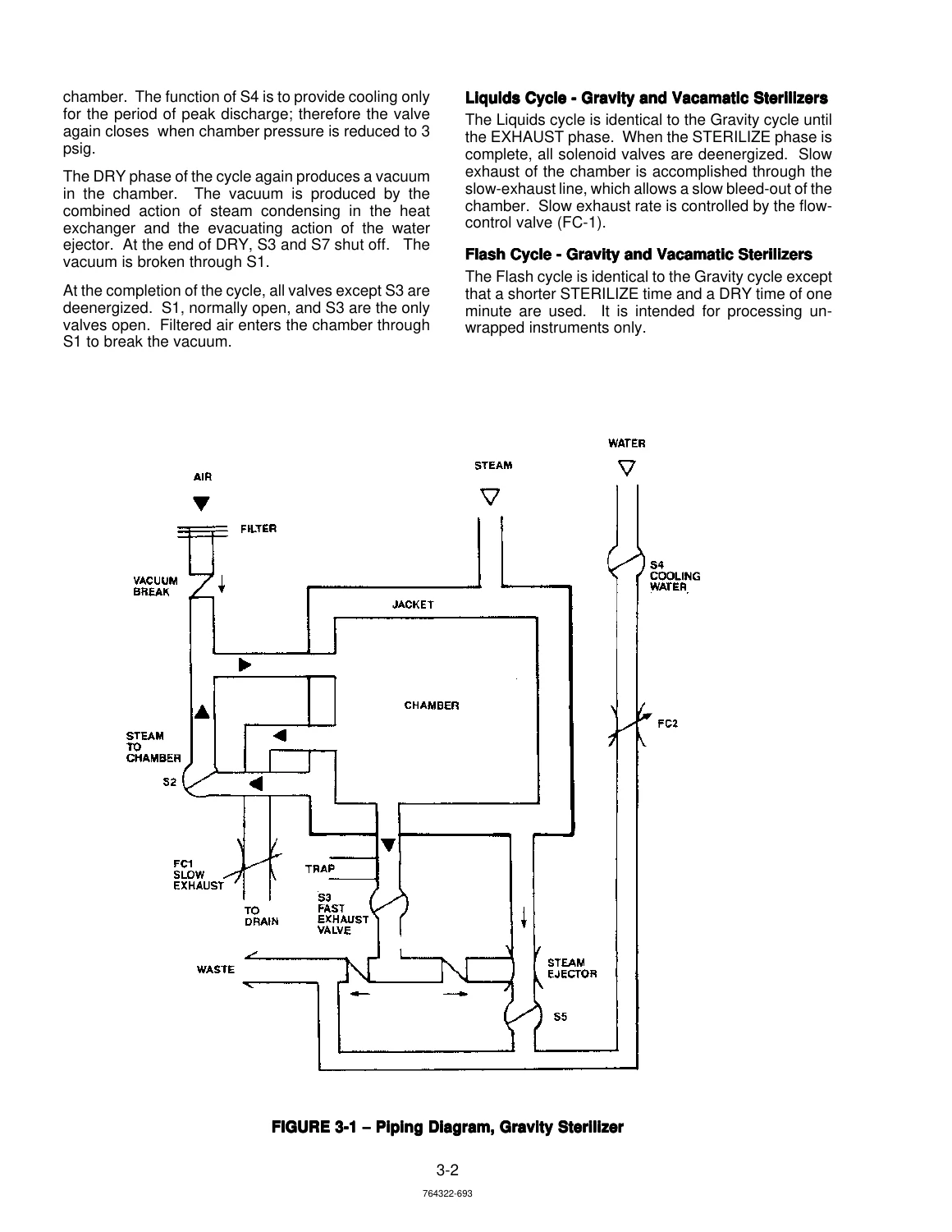
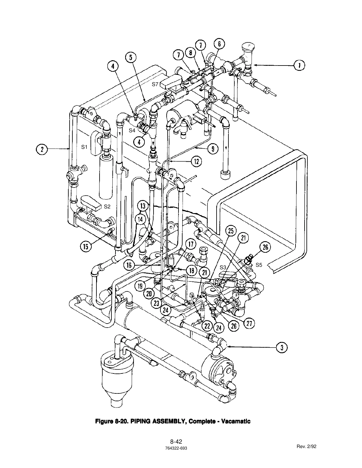
Put together, the chapters form a complete maintenance lifecycle for the Eagle 3000 sterilizer: setup and calibration, day-to-day preventive maintenance, cycle-by-cycle operational testing, in-depth troubleshooting of both electrical and mechanical faults, component-level repair and replacement, and the full illustrated parts breakdown needed to order the correct part the first time. The piping diagrams, cycle graphs, solenoid valve charts, and exploded views in particular make the electrical and mechanical sections far easier to follow than a text-only manual would allow.
What This Manual Covers In Practice
Whether the unit in front of you is a Gravity or Vacamatic Eagle 3000, this manual addresses the systems that actually fail: solenoid valves (S1 through S9), the chamber door lock and diaphragm, the steam trap and strainers, the HI-LO steam control valve, the thermistor temperature probe, the pressure transducer, the Control and Printer PC boards, the touch panel, the printer, the electric steam generator, and the anti-flood circuit. The Field Test Procedure in Section 5 alone covers door switch torque checks, cooling water valve settings, vacuum leak tests, pressure door lock tests, sensor calibration, and a full operational test with expected display messages for every phase of every cycle.
Why It Matters
Sterilizers operate under pressure and at high temperature, so getting a valve setting, a calibration, or a door switch adjustment wrong is not just an inconvenience. This manual provides the specific pressures, temperatures, torque values, timed phases, and valve states that each cycle is supposed to run at, along with the display messages and printouts the control should show at each step. With those numbers in hand, a technician can verify correct operation, isolate the failing component, and complete the repair using the exploded views and part numbers directly from the same document.
IMAGES PREVIEW
Instant PDF Delivery – Print It, Keep It on the Bench, Use It on Any Device
The AMSCO Eagle 3000 Small Sterilizers Maintenance Manual is delivered as an instant-download PDF. There is no shipping, no waiting, and no lost paper copy. You can open it on a laptop in the mechanical room, pull it up on a tablet next to the sterilizer, or print the section you need and take it into the field. The exploded views and cycle graphs are laid out on their own pages, so they print cleanly for a bench copy. Whether you are bringing a decommissioned unit back into service, planning a preventive maintenance visit, or diagnosing a fault the day it shows up on the printer tape, this is the reference that gets you to the correct procedure and the correct part without guessing.
What Our Customers Say
π Related Products
Discover more professional manuals for your equipment

Toshiba Xario 200 / Xario 100 (TUS-X200 / TUS-X100) Ultrasound System Service Note - SD730-440END

M860 Patient Monitor User Manual PDF β Biolight Meditech Operator Guide

Nipro SURDIAL 55Plus Single Patient Dialysis Machine Maintenance Manual 2010


Reviews
There are no reviews yet.