
Aprio K4M Engine Control System Section EC Repair Manual – EMS Gasoline Injection Diagnostics
Original price was: $34.95.$21.95Current price is: $21.95.
Section EC engine control system repair manual for the Aprio with K4M gasoline injection and EMS calculator – component locations, ECM terminal assignments, fault code interpretation, OBD diagnostics, live data parameters and tightening pairs across 120 pages.
Description
Section EC of the engine control system repair manual covers the EMS gasoline injection system used on the Aprio with the K4M engine. Rather than a generic overview of electronic injection, this section works through the system the way a technician actually meets it in the workshop: where each sensor and actuator sits, which ECM terminal feeds it, what the calculator does with the signal, and what to do when a fault code appears. The Aprio K4M Engine Control System Section EC Repair Manual is built around the CONSULT-III diagnostic tool, the ECM terminal blocks and the manufacturer fault-code tables, so every procedure points to a numbered union, a measurable value or a named state rather than a vague instruction to check the circuit.
File Details
- Manual type: Engine control system repair manual section (Section EC)
- Vehicle: Aprio
- Engine: K4M gasoline injection
- Calculator: EMS injection calculator, program no. E0 (K4M engines)
- Language: English, with a Spanish-language diagnostic worksheet example
- Page count: 120 pages
- File format: PDF
Chapters Covered
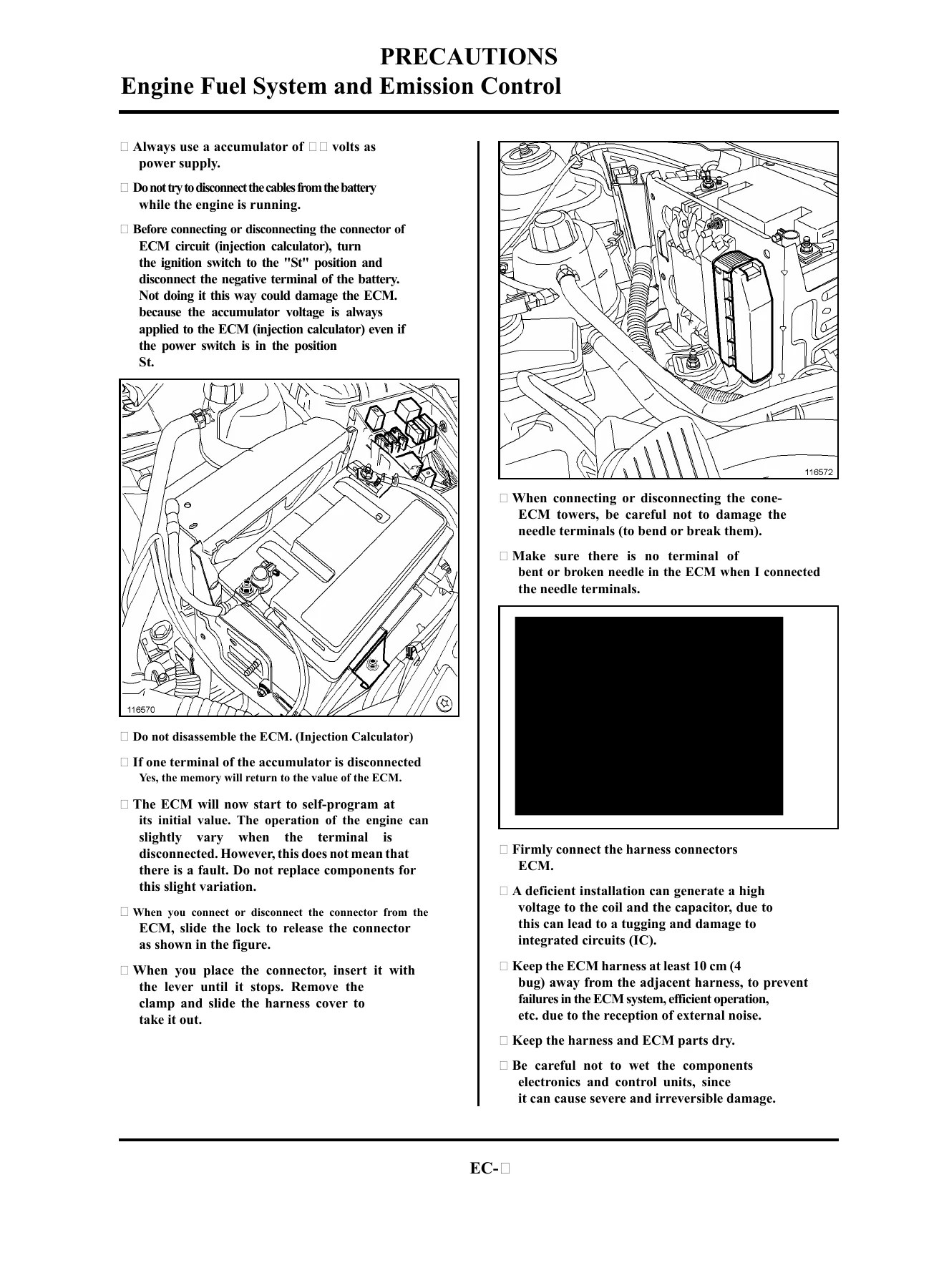
- Preparations – Special Service Tools, precautions for the diagnostic system in the vehicle
- Fault Diagnosis – electrical diagrams and fault diagnosis, diagnostic worksheet example
- Engine Control System – component location
- Particularities of sequential injection
- Inputs and outputs of the ECM
- Diagnosis – basic inspection, failure index, preliminaries, system operation
- Diagnosis – data monitoring and specifications
- Diagnosis – assignment of terminals from the calculator
- Diagnosis – component replacement, settings and learnings
- Diagnosis – summary table of failures and interpretation of failures
- Fuel injection – interpretation of the failures
- Engine control system – diagnosis help
- Data monitoring and specifications; summary table of the states, interpretation of the states
- Summary table of the parameters; interpretation of the parameters
- Summary table of the commands; interpretation of the controls
- Incidents detected by the client; failure localisation
- Tightening pairs
Read end to end, this section is a complete working reference for the EMS injection calculator: what it reads, what it drives, how it fails and how to prove where the failure is. The fault interpretation pages alone run from DF002 through DF120 and beyond, covering the butterfly potentiometer circuit, air and water temperature sensing, the knock pick-up, the actuator relay control circuit, canister purge solenoid, crankshaft position signal, front and rear oxygen sensor heating, the anti-start circuit, manifold pressure sensor, all four injectors individually, idle speed control, both ignition coil circuits, vehicle speed information, and the OBD indicator circuit. Each entry states whether the fault is current or past, what conditions make a stored fault reappear, and the exact connector, resistance value or terminal pair to test next.
Diagnosing by Fault Code, Not by Guesswork
The interpretation pages are written for someone holding a multimeter and a terminal block, not for someone browsing theory. A butterfly potentiometer fault sends you to the sensor resistance figures of roughly 1,200 ohms on the track and up to about 1,050 ohms at the cursor. An injector circuit fault names the cylinder, gives the coil resistance window and tells you which terminal should show 0 V with the ignition in the M position. An ignition coil 1-4 or 2-3 fault walks through primary and secondary resistance, the pencil coil connection, and the fuel pump relay terminal that feeds the coils. Throughout, priority rules tell you which fault to confirm first when several are stored at once – actuator relay and 5 V supply faults outrank the sensors that depend on them. Wiring checks are specified against the injection calculator terminals and the universal terminal blocks, so you can prove insulation, continuity and the absence of parasitic resistance union by union instead of replacing parts on suspicion.
OBD Readiness, Road Tests and Adaptive Learnings
An entire strand of the manual deals with the OBD side of the system: the conditions that authorise catalyst and oxygen sensor diagnostics, the combustion rate diagnostics that watch for a cylinder dropping out, and the learnings that have to be completed before those diagnostics will run. It explains the flywheel toothed crown learning carried out through decelerations with fuel cut in second through fifth gear, the road test used to bring adaptive richness corrections to life across the manifold pressure zones, and the reset-and-relearn sequence that follows clearing the calculator memory. There is also the practical warning that turning the ignition off before reading a result on the CONSULT-III invalidates the test – the kind of detail that separates a confirmed repair from a comeback.
Live Data, States, Parameters and Commands
Beyond fault codes, the manual catalogues what the calculator can show you while the engine is running and what each value should look like. Parameters include manifold pressure, water and air temperature, calculator supply voltage, engine speed, front and rear oxygen sensor voltage, adaptive richness at idle and under load, idle speed setting, injection duration, ignition advance, refrigerant fluid pressure and the power absorbed by the air conditioning compressor, each with an interpretation page for values that fall outside the expected range. States such as wealth regulation, double loop, idle regulation, oxygen sensor heating, cylinder 1 recognition and combustion rate per cylinder are listed with what ACTIVE or INACTIVE actually means for diagnosis. Command tests let you fire the fuel pump relay, the idle speed control valve, the canister purge solenoid, the oxygen sensor heaters, the fan motor group relays and the OBD indicator, so components can be exercised on the bench-side of the connector.
Component Location and Reference Values
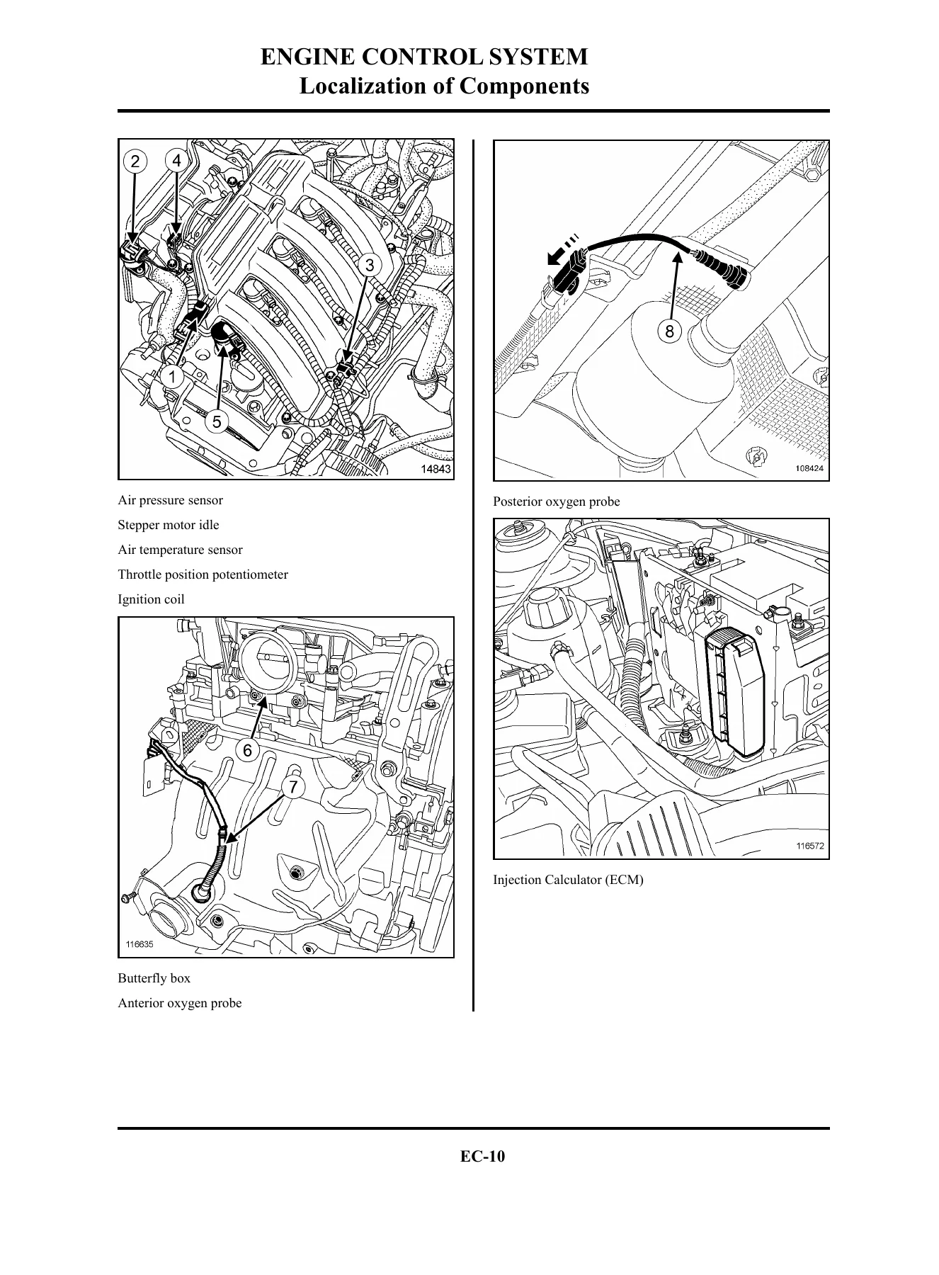
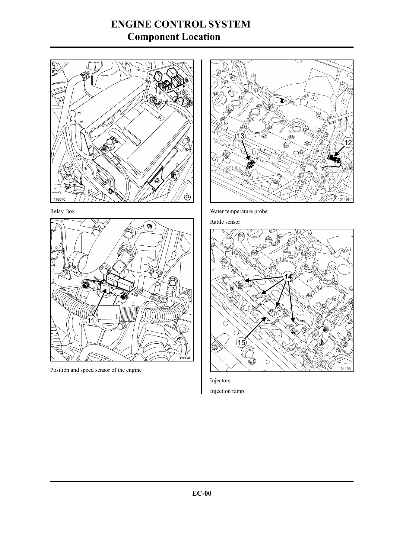
The opening pages place every part in the engine bay with numbered illustrations – air pressure sensor, idle stepper motor, air temperature sensor, throttle position potentiometer, ignition coils, front and rear oxygen probes, the injection calculator itself, the relay box, crankshaft position and speed sensor, water temperature probe, knock sensor, injectors, injection ramp, canister purge solenoid valve and the gasoline vapour absorber. The reference data section at the back collects the resistance and tolerance values in one place, including throttle potentiometer track and cursor values, idle stepper motor resistance, pencil coil primary and secondary resistance for the K4M, injector resistance, oxygen sensor heater resistances, top dead centre pick-up resistance, canister purge solenoid resistance, and air and water temperature sensor resistance curves at 0, 10, 25, 50, 80 and 110 degrees. Torque figures appear in the tightening pairs table.
Put the Section EC Manual to Work
IMAGES PREVIEW
With this Aprio K4M Engine Control System Section EC Repair Manual on hand you can read and clear injection faults, trace a stored or intermittent code back to the exact circuit that caused it, confirm a repair with the road tests and learnings the calculator expects, and check live data against the values the manufacturer published. That matters because the injection calculator, the oxygen sensors, the catalyst and the anti-start coding are all interlinked – replacing the wrong part costs more than the manual, and skipping a learning leaves the vehicle with an OBD light that comes back. The section also covers the anti-start coding state of the calculator, telling you how to confirm whether a calculator has learned the vehicle code and why a borrowed or unlearned unit will not start the engine. Delivery is an instant PDF download after payment, no shipping and no waiting, readable on a laptop, tablet or phone in the workshop and printable page by page for the bench. Keep the terminal assignment charts and the fault interpretation pages next to the car, and work through the electrical checks in the order the manual sets out.

Reviews
There are no reviews yet.