Volkswagen Golf 2013-2015 Golf Variant e-Golf Suspension Wheels & Steering Repair Manual
$39.95 Original price was: $39.95.$24.95Current price is: $24.95.
Comprehensive workshop repair manual covering suspension, running gear, wheels, alignment, and steering systems for Volkswagen Golf 2013+, Golf Variant 2014+, and e-Golf 2014+ models.
Description
Complete Running Gear Workshop Manual for Volkswagen Golf Mk7 Platforms
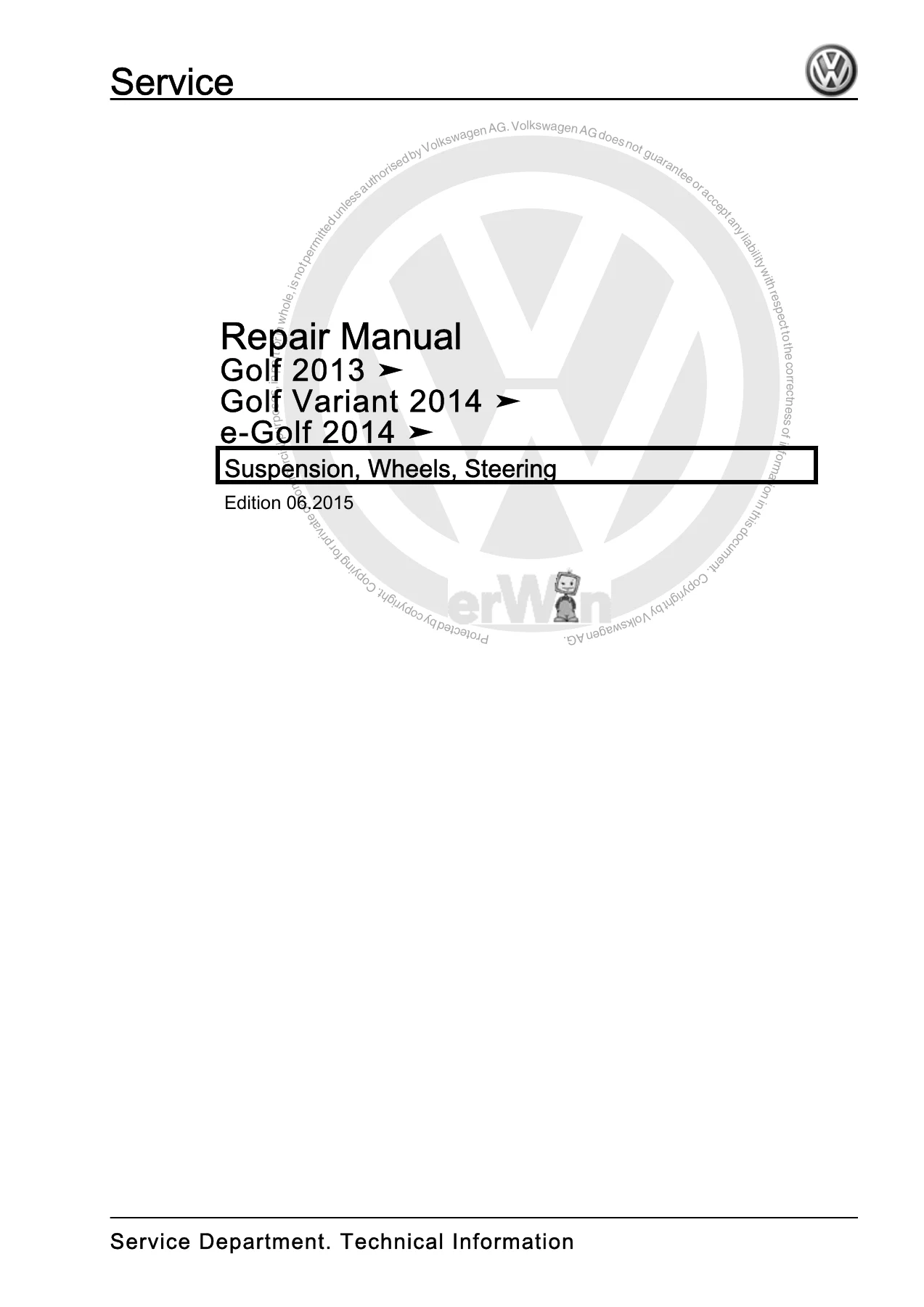
Perform precise running gear repairs, axle overhauls, steering gear replacements, and electronic chassis calibrations with the Volkswagen Golf 2013-2015 Golf Variant e-Golf Suspension Wheels & Steering Repair Manual. Published in June 2015 under document edition 06.2015 (Document ID: D4B8046FF18), this extensive technical guide contains 469 pages of factory-level technical information, exploded component diagrams, step-by-step disassembly and assembly instructions, and exact torque specifications for Volkswagen Golf 2013, Golf Variant 2014, and e-Golf 2014 vehicle families.
File Details
- Manual Type: Workshop Service & Repair Manual
- Brand & Models Covered: Volkswagen Golf 2013 >>, Golf Variant 2014 >>, e-Golf 2014 >> (including GTI, GTD, GTE, BlueMotion, Golf R, and Alltrack variants)
- Edition / Publication Date: Edition 06.2015 (D4B8046FF18)
- Language: English
- Page Count: 469 pages
- File Format: Adobe Acrobat PDF
Chapters Covered
- Repair Group 00 – General, Technical Data
- Safety Precautions: Working on Vehicles with Start/Stop System; Subframe Safety Instructions
- Repair Information: Shock Absorber Leakage Evaluation; Shock Absorber Noise Diagnosis; Removed Shock Absorber Inspection
- Steering Gear Cleanliness and Assembly Precautions
- Seals, Gaskets, Self-Locking Fasteners, and Static Discharge Protection
- Wheel Bearing in Curb Weight Position (Standing Height Measurement Table)
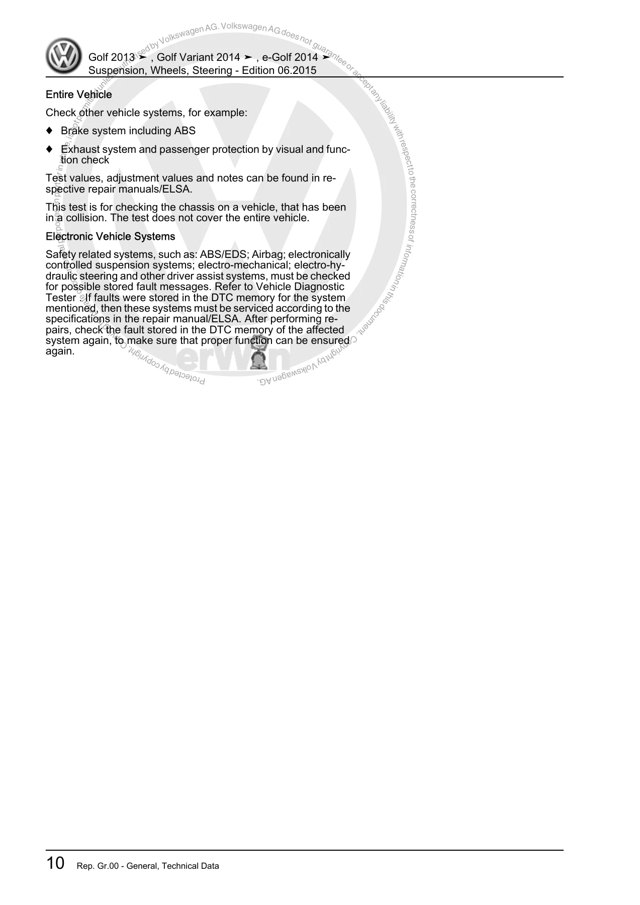
- Collision Vehicle Chassis Evaluation Checklist
- Disposal Procedures: Front and Rear Standard and DCC Gas-Filled Shock Absorber Venting and Draining
- Special Tools and Workshop Equipment
- Repair Group 40 – Front Suspension
- Front Axle Component Location Overview
- Subframe Removal and Installation (with and without Steering Gear; Conventional, Hybrid GTE, and e-Golf Models)
- Subframe Servicing: Hydraulic Press Removal and Installation of Pendulum Support Bonded Rubber Bushings
- Stabilizer Bar and Coupling Rod Removal and Installation
- Subframe Securing with Locating Pins and Subframe Lowering Procedures
- Suspension Strut Removal, Installation, and Disassembly with Spring Compressor Tooling
- Lower Control Arm and Ball Joint Removal, Inspection, and Bushing Replacement (Manual Transmission, DSG 0CW, and DSG 0D9)
- Wheel Bearing Housing and Wheel Bearing Unit Removal and Installation
- Drive Axle Assemblies: CV Joint VL 100, CV Joint VL 107, and Triple Roller Joint AAR3300i (Attached and Bolted Versions)
- Drive Axle Disassembly, Assembly, Boot Replacement, Spline Pasting, and Joint Wear Inspection
- Front Suspension Special Tools Reference
- Repair Group 42 – Rear Suspension
- Rear Axle Configurations: Torsion Beam Axle, Multi-Link Suspension FWD, and Multi-Link Suspension AWD (4Motion)
- Rear Axle Lowering Procedures (FWD Conventional, e-Golf, and AWD Models)
- Rear Axle Removal and Installation (Torsion Beam, Multi-Link FWD, e-Golf, Golf GTE with Fuel Tank Lowering, and AWD Final Drive Integration)
- Axle Beam Servicing and Bonded Rubber Bushing Replacement
- Subframe Securing, Alignment, and Bushing Overhaul
- Rear Stabilizer Bar, Coupling Rod, Upper and Lower Transverse Links, and Tie Rod Replacement
- Rear Shock Absorbers, Coil Springs, Trailing Arms, and Wheel Bearing Housing Servicing
- AWD Rear Drive Axles: Removal, Joint Inspection, Boot Servicing, and Hardware Specifications
- Rear Suspension Special Tools Reference
- Repair Group 43 – Self-Leveling Suspension
- Electronic Damping (DCC) System Architecture and Component Layout
- Electronic Damping Control Module J250 Removal and Installation
- Left Front and Right Front Body Acceleration Sensors G341 / G342
- Rear Body Acceleration Sensor G343 Removal and Installation
- Front Level Control System Sensors G78 / G289 and Rear Sensors G76 / G77
- Level Sensor Bracket Positioning and Diagnostic Basic Settings
- Self-Leveling Suspension Special Tools
- Repair Group 44 – Wheels, Tires, Wheel Alignment
- Tire Mounting, Dismounting, Wheel Changing, and Wheel Bolt Tightening (120 Nm)
- Tire Mobility Kit and Sealant Disposal Guidelines
- Indirect Tire Pressure Monitoring System (TPMS) Operation and Reset Requirements
- Axle Alignment Prerequisites, Test Preparations, and Factory Specified Values
- Front and Rear Camber and Toe Adjustment Procedures
- Radial and Lateral Runout Compensation and Vibration Diagnosis
- Adaptive Cruise Control (ACC) Sensor Calibration and Reflector Setup
- Driver Assistance Systems Front Camera Calibration
- Wheel Alignment Special Tools
Complete PDF Bookmark TreeComplete Bookmarks
The complete bookmarks in the “Volkswagen Golf 2013-2015 Golf Variant e-Golf Suspension Wheels & Steering Repair Manual” are as follows:
+00 – General, Technical Datap. 7
+1 Safety Precautionsp. 7
1.1 Safety Precautions when Working on Vehicles with Start/Stop Systemp. 71.2 Safety Precautions when Working on Subframep. 7+2 Repair Informationp. 8
2.1 Shock Absorber Leaksp. 82.2 Shock Absorber Noisesp. 82.3 Shock Absorbers, Checking when Removedp. 92.4 Steering Gearp. 92.5 Seals and Gasketsp. 102.6 Bolts and Nutsp. 102.7 Electrical Componentsp. 10+2.8 Wheel Bearing in Curb Weight Position, Lifting Vehicles with Coil Springp. 11
2.8.1 Wheel Bearing in Curb Weight, Lifting Vehicles with Coil Spring, Front Axlep. 112.8.2 Wheel Bearing in Curb Weight, Rear Axle, Lifting Vehicles with Coil Springp. 12+3 Vehicles Involved in Collisions, Evaluatingp. 15
3.1 Collision Vehicle Evaluation Checklistp. 15+4 Disposalp. 17
+4.1 Front Gas-Filled Shock Absorbers, Venting and Drainingp. 17
4.1.1 Front Shock Absorbers, Venting and Emptying, Standard Shock Absorberp. 174.1.2 Front Shock Absorbers, Venting and Emptying, DCC Shock Absorberp. 18+4.2 Rear Gas-Filled Shock Absorbers, Venting and Drainingp. 18
4.2.1 Rear Shock Absorbers, Venting and Emptying, Standard Shock Absorberp. 184.2.2 Rear Shock Absorbers, Venting and Emptying, DCC Shock Absorberp. 195 Special Toolsp. 20+40 – Front Suspensionp. 21
+1 Front Axlep. 21
1.1 Component Location Overview – Front Axlep. 21+2 Subframep. 22
2.1 Overview – Subframep. 22+2.2 Subframe without Steering Gear, Removing and Installingp. 23
2.2.1 Subframe without Steering Gear, Removing and Installing, Except e-Golfp. 232.2.2 Subframe without Steering Gear, Removing and Installing, e-Golfp. 27+2.3 Subframe with Steering Gear, Removing and Installingp. 30
2.3.1 Subframe with Steering Gear, Removing and Installing, except e-Golfp. 302.3.2 Subframe with Steering Gear, Removing and Installing, e-Golfp. 352.3.3 Subframe with Steering Gear, Removing and Installing, RHD, except e-Golfp. 402.3.4 Subframe with Steering Gear, Removing and Installing, RHD, e-Golfp. 462.4 Subframe, Servicingp. 512.5 Stabilizer Bar, Removing and Installingp. 572.6 Coupling Rod, Removing and Installingp. 612.7 Thread in Longitudinal Member, Servicingp. 622.8 Subframe, Securingp. 62+2.9 Subframe, Loweringp. 65
2.9.1 Subframe, Lowering, Except e-Golfp. 652.9.2 Subframe, Lowering, e-Golfp. 68+3 Suspension Strut and Upper Control Armp. 72
3.1 Overview – Suspension Strut and Upper Control Armp. 723.2 Suspension Strut, Removing and Installingp. 733.3 Suspension Strut, Servicingp. 80+4 Lower Control Arm and Ball Jointp. 82
4.1 Overview – Lower Control Arm and Ball Jointp. 82+4.2 Lower Control Arm, Removing and Installingp. 83
4.2.1 Lower Control Arm, Removing and Installing, Vehicles with Manual Transmission, DSG® Transmission 0CWp. 834.2.2 Lower Control Arm, Removing and Installing, Vehicles with DSG® Transmission 0D9p. 854.3 Ball Joint, Checkingp. 884.4 Ball Joint, Removing and Installingp. 89+4.5 Lower Control Arm Bonded Rubber Bushing, Replacingp. 92
4.5.1 Front Lower Control Arm Bonded Rubber Bushing, Replacingp. 924.5.2 Lower Control Arm Rear Bonded Rubber Bushing, Replacingp. 94+5 Wheel Bearingp. 97
5.1 Overview – Wheel Bearingp. 975.2 Wheel Bearing Housing, Removing and Installingp. 975.3 Wheel Bearing Unit, Removing and Installingp. 102+6 Drive Axlep. 106
6.1 Overview – Drive Axlep. 106+6.2 Overview – Drive Axlep. 107
6.2.1 Overview – Drive Axle, CV Joint VL 100p. 1076.2.2 Overview – Drive Axle, CV Joint VL 107p. 1096.2.3 Overview – Drive Axle, Triple Roller Joint AAR3300ip. 111+6.3 Drive Axle, Removing and Installingp. 112
6.3.1 Drive Axle, Removing and Installing, Left Drive Axle, CV Joint VL 100 and VL 107, Except e-Golfp. 1126.3.2 Drive Axle, Removing and Installing, Right Drive Axle, CV Joint VL 100 and VL 107, Except e-Golfp. 1166.3.3 Drive Axle, Removing and Installing, Left Drive Axle, CV Joint VL 100 and VL 107, e-Golfp. 1206.3.4 Drive Axle, Removing and Installing, Right Drive Axle, CV Joint VL 100 and VL 107, e-Golfp. 1236.3.5 Drive Axle, Removing and Installing, Triple Roller Joint AAR3300i Attachedp. 1256.3.6 Drive Axle, Removing and Installing, Triple Roller Joint AAR3300i Boltedp. 1296.4 Drive Axle Threaded Connection, Loosening and Tighteningp. 1336.5 Drive Axle Heat Shield, Removing and Installingp. 134+6.6 Drive Axle, Disassembling and Assemblingp. 135
6.6.1 Drive Axle, Disassembling and Assembling, CV Joint VL100p. 1356.6.2 Drive Axle, Disassembling and Assembling, CV Joint VL107p. 1386.6.3 Drive Axle, Disassembling and Assembling, Triple Roller Joint AAR3300ip. 1406.7 Outer CV Joint, Checkingp. 1446.8 Inner CV Joint, Checkingp. 1457 Special Toolsp. 147+42 – Rear Suspensionp. 162
+1 Rear Axlep. 162
+1.1 Overview – Rear Axlep. 162
1.1.1 Overview – Rear Axle, Torsion Beam Axlep. 1621.1.2 Overview – Rear Axle, Multi-Link Suspensionp. 1631.1.3 Overview – Rear Axle, Multi-Link Suspension, AWDp. 165+1.2 Rear Axle, Loweringp. 166
1.2.1 Rear Axle, Lowering, Multi-link Suspension, FWD Except e-Golfp. 1661.2.2 Rear Axle, Lowering, Multi-link Suspension, FWD e-Golfp. 1691.2.3 Rear Axle, Lowering, Multi-Link Suspension, AWDp. 171+1.3 Rear Axle, Removing and Installingp. 174
1.3.1 Rear Axle, Removing and Installing, Torsion Beam Axlep. 1741.3.2 Rear Axle, Removing and Installing, Multi-Link Suspension, FWD, except e-Golf and Golf GTEp. 1761.3.3 Rear Axle, Removing and Installing, Multi-Link Suspension, FWD e-Golfp. 1791.3.4 Rear Axle, Removing and Installing, Multi-link Suspension, FWD, Golf GTEp. 1831.3.5 Rear Axle, Removing and Installing, Multi-Link Suspension, AWDp. 187+2 Axle Beamp. 190
2.1 Overview – Axle Beamp. 1902.2 Axle Beam Bonded Rubber Bushing, Replacingp. 190+3 Subframep. 197
+3.1 Overview – Subframep. 197
3.1.1 Overview – Subframe, Multi-Link Suspension, FWD Except e-Golfp. 1973.1.2 Overview – Subframe, Multi-Link Suspension, FWD e-Golfp. 1983.1.3 Overview – Subframe, Multi-Link Suspension, AWDp. 199+3.2 Subframe, Securingp. 199
3.2.1 Subframe, Securing, Multi-Link Suspension, FWD, except e-Golf and Golf GTEp. 1993.2.2 Subframe, Securing, Multi-Link Suspension, FWD e-Golfp. 2033.2.3 Subframe, Securing, Multi-link Suspension, FWD, Golf GTEp. 2083.2.4 Subframe, Securing, Multi-Link Suspension, AWDp. 212+3.3 Subframe, Servicingp. 215
3.3.1 Front Bonded Rubber Bushing, Replacingp. 2153.3.2 Rear Bonded Rubber Bushing, Replacingp. 221+4 Stabilizer Barp. 227
+4.1 Overview – Stabilizer Barp. 227
4.1.1 Overview – Stabilizer Bar, Multi-Link Suspension, FWDp. 2274.1.2 Overview – Stabilizer Bar, Multi-Link Suspension, AWDp. 2284.2 Stabilizer Bar, Removing and Installingp. 2284.3 Coupling Rod, Removing and Installingp. 229+5 Control Arm, Tie Rodp. 232
+5.1 Overview – Transverse Linkp. 232
5.1.1 Overview – Transverse Link, Multi-Link Suspension, FWDp. 2325.1.2 Overview – Transverse Link, Multi-Link Suspension, AWDp. 234+5.2 Overview – Tie Rodp. 236
5.2.1 Overview – Tie Rod, Multi-Link Suspension, FWDp. 2365.2.2 Overview – Tie Rod, Multi-Link Suspension, AWDp. 237+5.3 Upper Transverse Link, Removing and Installingp. 237
5.3.1 Upper Transverse Link, Removing and Installing, FWDp. 2375.3.2 Upper Transverse Link, Removing and Installing, AWDp. 2385.4 Lower Transverse Link, Removing and Installingp. 2395.5 Tie Rod, Removing and Installingp. 241+6 Suspension Strut/Shock Absorber, Springp. 243
+6.1 Overview – Suspension Strut, Shock Absorber and Springp. 243
6.1.1 Overview – Suspension Strut, Shock Absorber and Spring, Torsion Beam Axlep. 2436.1.2 Overview – Suspension Strut, Shock Absorber and Spring, Multi-Link Suspensionp. 244+6.2 Shock Absorber, Removing and Installingp. 245
6.2.1 Shock Absorber, Removing and Installing, Torsion Beam Axlep. 2456.2.2 Shock Absorber, Removing and Installing, Multi-Link Suspension, Left Shock Absorberp. 2476.2.3 Shock Absorber, Removing and Installing, Multi-Link Suspension, Right Shock Absorberp. 2496.3 Shock Absorber, Servicingp. 252+6.4 Spring, Removing and Installingp. 254
6.4.1 Spring, Removing and Installing, Torsion Beam Axlep. 2546.4.2 Spring, Removing and Installing, Multi-Link Suspension, Left Spring FWD, Left and Right Spring AWDp. 2566.4.3 Spring, Removing and Installing, Multi-Link Suspension, Right Spring, FWDp. 258+7 Wheel Bearing and Trailing Armp. 263
+7.1 Overview – Wheel Bearingp. 263
7.1.1 Overview – Wheel Bearing, Torsion Beam Axlep. 2637.1.2 Overview – Wheel Bearing, Multi-Link Suspension, FWDp. 2657.1.3 Overview – Wheel Bearing, Multi-Link Suspension, AWDp. 266+7.2 Overview – Trailing Armp. 267
7.2.1 Overview – Trailing Arm, Except e-Golfp. 2677.2.2 Overview – Trailing Arm, e-Golfp. 268+7.3 Wheel Bearing Housing, Removing and Installingp. 268
7.3.1 Wheel Bearing Housing, Removing and Installing, Multi-Link Suspension, FWDp. 2687.3.2 Wheel Bearing Housing, Removing and Installing, Multi-Link Suspension, AWDp. 272+7.4 Wheel Bearing Unit, Removing and Installingp. 277
7.4.1 Wheel Bearing Unit, Removing and Installing, Torsion Beam Axlep. 2777.4.2 Wheel Bearing Unit, Removing and Installing, Multi-Link Suspension, FWDp. 2797.4.3 Wheel Bearing Unit, Removing and Installing, Multi-Link Suspension, AWDp. 282+7.5 Wheel Bearing Housing Bonded Rubber Bushing, Replacingp. 284
7.5.1 Wheel Bearing Housing Bonded Rubber Bushing, Replacing, FWDp. 2847.5.2 Wheel Bearing Housing Bonded Rubber Bushing, Replacing, AWDp. 286+7.6 Trailing Arm with Mounting Bracket, Removing and Installingp. 289
7.6.1 Trailing Arm with Mounting Bracket, Removing and Installing, Except e-Golfp. 2897.6.2 Trailing Arm with Mounting Bracket, Removing and Installing, e-Golfp. 2927.7 Trailing Arm, Servicingp. 295+8 Drive Axlep. 298
8.1 Overview – Drive Axlep. 2988.2 Drive Axle, Removing and Installingp. 2998.3 Drive Axle, Disassembling and Assemblingp. 3038.4 Drive Axle Threaded Connection, Loosening and Tighteningp. 3068.5 Outer CV Joint, Checkingp. 3078.6 Inner CV Joint, Checkingp. 3099 Special Toolsp. 311+43 – Self-Leveling Suspensionp. 323
+1 Electronic Dampingp. 323
+1.1 Overview – Electronic Dampingp. 323
1.1.1 Overview – Electronic Damping, Torsion Beam Axle, Sedanp. 3231.1.2 Overview – Electronic Damping, Multi-Link Suspension, Sedanp. 3251.1.3 Overview – Electronic Damping, Multi-Link Suspension, Wagonp. 327+1.2 Electronic Damping Control Module -J250-, Removing and Installingp. 328
1.2.1 Electronic Damping Control Module -J250-, Removing and Installing, Sedanp. 3281.2.2 Electronic Damping Control Module -J250-, Removing and Installing, Wagonp. 3291.3 Left/Right Front Body Acceleration Sensor – G341-/-G342-, Removing and Installingp. 3301.4 Rear Body Acceleration Sensor -G343-, Removing and Installingp. 331+2 Level Control System Sensorp. 333
2.1 Overview – Front Level Control System Sensorp. 333+2.2 Overview – Rear Level Control System Sensorp. 334
2.2.1 Overview – Rear Level Control System Sensor, Torsion Beam Axlep. 3342.2.2 Overview – Rear Level Control System Sensor, Multi-Link Suspension, FWDp. 3352.2.3 Overview – Rear Level Control System Sensor, Multi-Link Suspension, AWDp. 3362.3 Left/Right Front Level Control System Sensor -G78-/-G289-, Removing and Installingp. 336+2.4 Left/Right Rear Level Control System Sensor – G76-/-G77-, Removing and Installingp. 338
2.4.1 Left Rear Level Control System Sensor -G76-, Removing and Installing, Torsion Beam Axlep. 3382.4.2 Left Rear Level Control System Sensors -G76-, Removing and Installing, Multi-Link Suspension, FWDp. 3382.4.3 Left Rear Level Control System Sensors -G76-, Removing and Installing, Multi-Link Suspension, AWDp. 3393 Special Toolsp. 340+44 – Wheels, Tires, Wheel Alignmentp. 341
+1 Wheels and Tiresp. 341
1.1 Tires, Dismountingp. 3411.2 Tires, Mountingp. 341+1.3 Wheel, Changingp. 342
1.3.1 Wheel Changing, Protecting Wheel Centering Seat Against Corrosionp. 3421.3.2 Wheel, Changingp. 3431.3.3 Wheel Changing Instructionsp. 3441.3.4 Wheel Changing and Wheel Installationp. 3451.3.5 Wheel Changing, Position of Anti-Theft Wheel Bolts on Steel Wheelsp. 3451.4 Wheel Bolt Tightening Specificationsp. 3461.5 Tires, Dismountingp. 3461.6 Tire Sealant, Disposingp. 347+1.7 Vehicles with Tire Mobility Kitp. 347
1.7.1 Vehicles with Break-Down Kit, Sedanp. 3471.7.2 Vehicles with Break-Down Kit, Wagonp. 348+2 Tire Pressure Monitoring Systemp. 349
2.1 System Description – Tire Pressure Monitoring Systemp. 349+3 Vehicle Alignmentp. 351
3.1 Axle Alignment Informationp. 3513.2 Test Requirementsp. 351+3.3 Measure Preparationsp. 352
3.3.1 Measurement Preparations, Axle Alignment without Driver Assistance Systemsp. 3523.3.2 Measurement Preparations, Axle Alignment with Driver Assistance Systemsp. 353+3.4 Axle Alignment Specified Valuesp. 353
3.4.1 Axle Alignment Specified Values, Torsion Beam Axle, Golfp. 3533.4.2 Axle Alignment Specified Values, Torsion Beam Axle, Golf Wagonp. 3553.4.3 Axle Alignment Specified Values, Multi-Link Suspension, Golfp. 3563.4.4 Axle Alignment Specified Values, Multi-Link Suspension, Golf Wagon, Golf Wagon R, Golf Alltrackp. 3593.4.5 Axle Alignment Specified Values, Multi-Link Suspension, e-Golfp. 3603.5 Vehicle, Preparing for Aligningp. 3613.6 Axle Alignment Procedurep. 361+3.7 Need for Axle Alignment, Evaluatingp. 363
3.7.1 Evaluating Need for Axle Alignment, Torsion Beam Axlep. 3633.7.2 Evaluating Need for Axle Alignment, Multi-Link Suspensionp. 3643.8 Front Axle Camber, Adjustingp. 365+3.9 Rear Axle Camber, Adjustingp. 366
3.9.1 Rear Axle Camber, Adjusting, Torsion Beam Axlep. 3663.9.2 Rear Axle Camber, Adjusting, Multi-Link Suspensionp. 366+3.10 Rear Axle Toe, Adjustingp. 367
3.10.1 Rear Axle Toe, Adjusting, Torsion Beam Axlep. 3673.10.2 Rear Axle Toe, Adjusting, Multi-Link Suspensionp. 3673.11 Front Axle Toe, Adjustingp. 3683.12 Wheel Run-Out Compensationp. 3693.13 Vehicle Data Labelp. 3693.14 Maximum Steering Angle, Checkingp. 369+4 Wheel/Tire Vibration, Causes and Solutionp. 371
4.1 Vibration Causesp. 3714.2 Road Test, Performing Before Balancingp. 371+4.3 Wheel, Balancingp. 372
4.3.1 Wheel, Balancingp. 3724.3.2 Wheel, Balancing on Stationary Balancing Machinep. 3724.3.3 Wheel, Balancing with Fine Balancing Machine (Finish Balancer)p. 3754.4 Vibration Control Systemp. 376+4.5 Tire and Wheel Radial and Lateral Run-Out, Checkingp. 376
4.5.1 Tire and Wheel Radial and Lateral Run-Out, Checking, Tolerancesp. 3764.5.2 Wheels and Tires, Radial and Lateral Run Out, Checking with Tire Dial Gaugep. 3774.6 Rim Radial and Lateral Run-Out, Checkingp. 3774.7 Wheels and Tires, Matchingp. 3784.8 Flat Spots in Tires From Standing, Determiningp. 379+5 Adaptive Cruise Control (ACC)p. 381
+5.1 Adaptive Cruise Control (ACC), Calibratingp. 381
5.1.1 Adaptive Cruise Control (ACC), Calibrating, Except e-Golfp. 3815.1.2 Adaptive Cruise Control (ACC), Calibrating, e-Golfp. 387+6 Driver Assistance Systems Front Camerap. 393
6.1 Driver Assistance Systems Front Camera, Calibratingp. 3937 Special Toolsp. 400+48 – Steeringp. 402
+1 Steering Wheelp. 402
1.1 Overview – Steering Wheelp. 4021.2 Steering Wheel, Removing and Installingp. 402+2 Steering Columnp. 404
2.1 Overview – Steering Columnp. 4042.2 Steering Column, Checking for Damagep. 4052.3 Steering Column, Handling and Transportingp. 405+2.4 Steering Column, Removing and Installingp. 406
2.4.1 Steering Column, Removing and Installingp. 4062.4.2 Steering Column, Removing and Installing, RHDp. 4142.5 Electronic Steering Column Lock Control Module -J764-, Removing and Installingp. 423+3 Steering Gearp. 425
+3.1 Overview – Steering Gearp. 425
3.1.1 Overview – Steering Gearp. 4253.1.2 Overview – Steering Gear, RHDp. 427+3.2 Steering Gear, Removing and Installingp. 428
3.2.1 Steering Gear, Removing and Installing, except e-Golfp. 4283.2.2 Steering Gear, Removing and Installing, e-Golfp. 4343.2.3 Steering Gear, Removing and Installing, RHD, except e-Golfp. 4403.2.4 Steering Gear, Removing and Installing, RHD e-Golfp. 4473.3 Boot, Removing and Installingp. 4543.4 Tie Rod, Removing and Installingp. 4563.5 Tie Rod End, Removing and Installingp. 4583.6 Steering Gear, Servicingp. 459+4 Sensorsp. 462
4.1 Steering Angle Sensor -G85-, Removing and Installingp. 4625 Special Toolsp. 4636 Revision Historyp. 466 - Repair Group 48 – Steering
- Steering Wheel Removal and Installation
- Steering Column Assembly, Transport Handling, Safety Checks, and Replacement
- Electronic Steering Column Lock Control Module J764 Servicing
- Electro-Mechanical Steering Gear Removal, Installation, and Overhaul
- Steering Gear Bellows Boots, Tie Rods, and Tie Rod Ends Servicing
- Steering Angle Sensor G85 Removal and Centering
- Steering System Special Tools
This technical service manual gives mechanics, workshop technicians, and advanced owners comprehensive engineering instructions directly from the manufacturer. By detailing distinct procedures across all running gear layouts—from lightweight torsion beam rear axles to complex multi-link all-wheel-drive configurations and high-voltage e-Golf drivetrains—the manual eliminates guesswork, prevents improper bushing preloading, and ensures exact assembly standards across every component.
Critical Procedures and Factory Technical Specifications
Working on modern MQB-platform chassis requires rigorous adherence to manufacturer protocols. The Volkswagen Golf 2013-2015 Golf Variant e-Golf Suspension Wheels & Steering Repair Manual provides explicit technical procedures that safeguard components from premature wear and structural failure:
- Curb Weight Tightening Rules: Bonded rubber bushings have a strictly limited operating angle. Tightening pivot bolts while the suspension hangs unsupported introduces severe torsional stress that rapidly tears the rubber. This manual provides the definitive curb weight standing height measurement table (dimension -a- measured from wheel hub center to the lower edge of the wheel housing) across every suspension package: Basic (383±10 mm front / 385±10 mm rear), Sport (368±10 mm / 370±10 mm), Raised Rough-Road (398±10 mm / 400±10 mm), DCC Dynamic Chassis Control (373±10 mm / 375±10 mm), GTD (368±10 mm / 370±10 mm), GTI (368±10 mm / 370±10 mm), BlueMotion (368±10 mm / 370±10 mm), GTI Heavy-Duty (383±10 mm / 385±10 mm), GTE Hybrid (383±10 mm / 395±10 mm), Golf R (363±10 mm / 365±10 mm), Alltrack (397±10 mm / 398±10 mm), and Alltrack DCC (392±10 mm / 393±10 mm). Technicians learn how to accurately simulate road height on the hoist using engine/gearbox jack VAS 6931 and adapter T10149 with tensioning straps T10038.
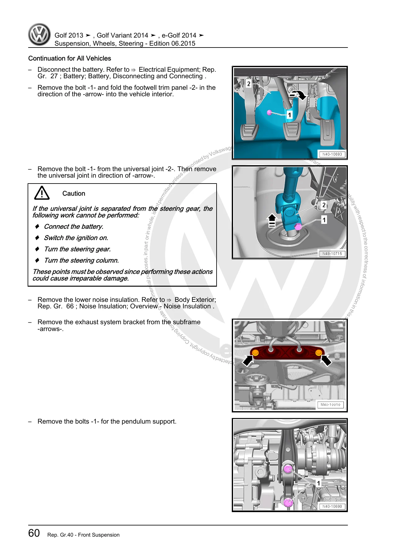
- Subframe Alignment and Removal: Complete instructions detail how to lower or remove the subframe assembly with or without the electro-mechanical steering rack attached. To ensure the front subframe returns to factory alignment without requiring front-end geometry recalibration, the manual details the sequential insertion and 20 Nm torque method for the four locating pins from assembly tool kit T10486/1. Specific instructions cover the removal of the high-voltage battery impact guard on e-Golf, high-voltage de-energization for Golf GTE, and exhaust bracket detachment.
- Drive Axle & CV Joint Servicing: Full overhaul guidelines cover constant velocity joint configurations VL 100, VL 107, and AAR3300i triple roller joints. Critical safety warnings forbid moving vehicles or placing weight on wheel bearings when drive axle bolts are loosened (limiting wheel-standing bolt release to a maximum of 90 degrees to avoid brinelling the bearing race). Step-by-step instructions cover the application of assembly paste to wheel hub splines, continuous sealing beads of D 454 300 A2 on joint covers, precise grease distribution (such as G 052 142 A2), stainless steel boot clamp tensioning using clamping pliers VAG 1682 A at 25 Nm, and the final twelve-point drive axle hub bolt tightening protocol (200 Nm + 180 degrees).
- Rear Axle Overhauls: Dedicated chapters address the mechanical variations across front-wheel drive and 4Motion all-wheel drive models. Step-by-step sequences guide the removal of torsion beam axle bushings using hydraulic press tools T10254 and T10495, multi-link subframe lowering via threaded spindle 3346/2 and bushing tool kit 3301, and Golf GTE rear subframe lowering requiring coordinated fuel tank detachment and EVAP line routing. AWD procedures include uncoupling the Haldex rear final drive and driveshaft without damaging centering pins or wiring harnesses.
- Driver Assistance & DCC Electronic Calibration: Beyond mechanical assembly, the manual provides end-of-repair requirements, including sensor positioning for front level sensors G78/G289 and rear sensors G76/G77, basic setting initiation for DCC control module J250, adaptive cruise control (ACC) radar beam alignment, and front windshield camera calibration for lane departure assist systems.
IMAGES PREVIEW
Professional Chassis Service Capability
Whether replacing a leaking shock absorber, renewing pressed-in lower control arm bushings, swapping out an electro-mechanical steering rack, or performing a four-wheel alignment following collision damage, having access to the Volkswagen Golf 2013-2015 Golf Variant e-Golf Suspension Wheels & Steering Repair Manual is indispensable. Incorrect torque values, improper bushing resting angles, or uncalibrated steering angle sensors can compromise electronic stability control, cause handling instability, and destroy costly components. This workshop repair manual provides verified procedures, critical warning notices, and clear exploded diagrams that empower technicians and owners to complete running gear overhauls safely, accurately, and to exact factory tolerances.
This manual is delivered as an instant digital PDF download immediately following purchase. There are no shipping delays or physical pages to keep clean in a greasy workshop environment. Store the document on your laptop, workshop tablet, or smartphone for immediate access at the vehicle hoist, or print out the specific procedural pages and torque charts you need for the job at hand.

What Our Customers Say
🌟 Related Products
Discover more professional manuals for your equipment

Isuzu TF Series 6VE1 3.5L Engine Workshop Manual Section 6


Honda Accord 1990-1993 Service Repair Manual - Complete Shop Manual Compilation


Reviews
There are no reviews yet.