

Atlas Copco DM30 Blasthole Drill Safety Operation and Maintenance Manual 2005
Original price was: $39.95.$24.95Current price is: $24.95.
Complete 644-page PDF service manual for the Atlas Copco DM30 Blasthole Drill covering safety, operation, maintenance, hydraulic and electrical systems, compressor service and troubleshooting.
Description
Atlas Copco DM30 Blasthole Drill Safety Operation and Maintenance Manual
This Atlas Copco DM30 Blasthole Drill Safety Operation and Maintenance Manual is the complete factory-issued document for the DM30 crawler-mounted, hydraulic tophread drive, multi-pass rotary blasthole drill. Published by Atlas Copco Drilling Solutions (Garland, Texas), this 644-page PDF covers everything from daily walk-around inspections to hydraulic circuit diagnostics, compressor regulation and full maintenance intervals.
Whether you run a DM30 on a quarry bench, a coal strip operation or a hard-rock DHD programme, this Atlas Copco DM30 manual gives you the operating controls, safety decals, torque values and troubleshooting charts needed to keep the machine drilling safely and productively.
File Details
- Manual type: Operating, Safety and Maintenance Manual
- Brand: Atlas Copco Drilling Solutions
- Model: DM30 BLASTHOLE
- Language: English
- Page count: 644 pages
- File format: PDF
- Date: 10/2005 (Sections 1–5, 7–8), 07/2006 Rev 03 (Section 6 – Maintenance)
- Revision: Rev 002 / Rev 03
Chapters Covered in the DM30 Blasthole Drill Manual
The DM30 service manual is organised into eight sections. The DM30 operating and maintenance manual contents include:
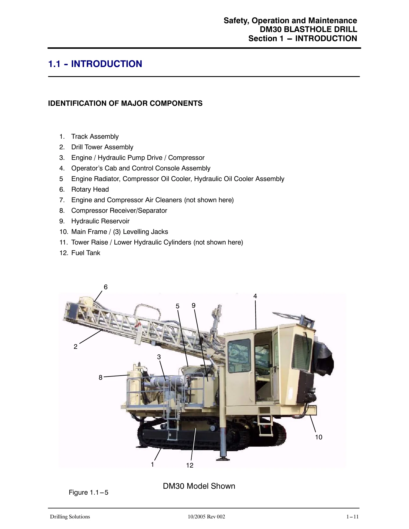
- Section 1 – Introduction: Drill description, how this manual is organised, procedure when receiving the drill, identification data (drill and engine), instruction manual storage, drill description, main frame, drill tower, controls, tramming, steering, braking, operator’s cab, gradeability, serviceability, standard features, identification of major components.
- Section 2 – Safety: General safety and health, safety and health statement, emergencies, safety precautions and guidelines, important safety instructions, warnings, drill applications (designated and non-designated), qualify your personnel, general guidelines, general rules, pre-start inspection, operation safety, starting safety, electrical power line safety, operating safety, drilling safety, propelling (tramming) safety, stopping and shutdown, maintenance safety, fueling, batteries, wire rope & cable, hydraulic maintenance safety, cylinder repairs or replacement, pumps and motors, valves, hoses, coolers and fans, guards, tracks, lubrication, compressor, warning of special dangers, overhead electric wires, ventilation, grade limitations, transporting and towing, safety decals & nameplates (full decal list with part numbers and locations), hazardous substance precaution, symbol identification.
- Section 3 – Specifications: Drill applications, operational limitations (ambient temperature, ground pressure, sound pressure, vibration exposure, maximum allowable slope angle), stability/gradeability chart, standard equipment and specifications, main frame, undercarriage and propel system, tower, carousel and drill pipe handling, drill pipe change, rotary head, feed system, power pack, cooling package, air compressor (low pressure and high pressure), engine specifications, hydraulic system, hydraulic reservoir, hydraulic pumps, hydraulic motors, cylinders (leveling jack, tower raising, tower pinning, feed, carousel swing, carousel index, chain wrench, dust hood, rod holder), dust collector, operator’s cab and console, night lights, deck service catwalk, optional equipment, standard tools and accessories, dimensions and weights.
- Section 4 – Operating Controls: Operator’s console, engine controls & instruments, Cummins engines, CAT engines, compressor discharge temperature switchgage, engine oil pressure gauge, diagnostic gauge, engine coolant temperature gauge, emergency stop, tachometer/hourmeter, engine throttle, engine start, key switch, engine fuel primer, heat/air conditioning, heat/air regulator, tram lights, drill lights, circuit breakers, fuel level gauge, ether injection, temperature regulator, tower raise/lower, cab side leveling jack, rear leveling jack, dust collector side leveling jack, breakout wrench, propel/drill mode selector, torque limit, supercharge pressure gauge, rotation speed, cable controls (left track & drill functions, right track & drill rotation), air throttle, interstage pressure, air volume, bit air pressure, water injection flow, compressor on/off, DHD lubricator, feed pressure gauge, rotation pressure gauge, drill feed control, feed pressure control, feed pressure shutoff, leveling jack indicator lights, water injection/dust collector, carousel swing, carousel index, service winch, dust hood, rod support option, tower pinning, air valve breakout wrench, bubble level, data link socket, windshield wiper selectors, inclinometers, hydraulic oil level gauge, hydraulic oil temperature gauge, engine preheater, battery isolation switch.
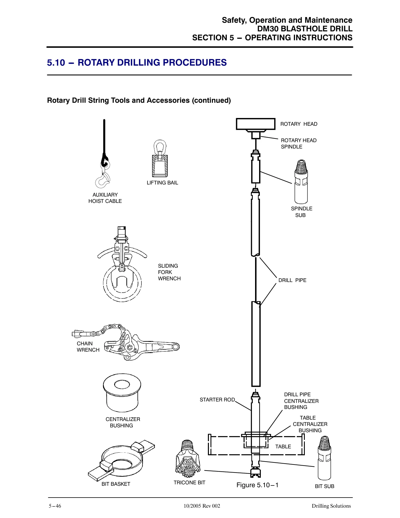
- Section 5 – Operating Instructions: Operating safety, walk-around inspection (hydraulic oil leaks, compressor oil leaks, coolant system leaks, engine fuel system leaks, general checks, operator’s areas), preliminary start inspection (engine lubricating oil level, engine coolant level, fuel level, fuel filter/water separator, compressor oil level, receiver tank, batteries, pump drive gearbox oil level, hydraulic oil level, operator’s areas), drill controls verification, engine operation (starting engine, engine pre-start procedure, starting the power unit, ether cold start option, gauges & controls, engine shutdown, emergency shutdown, starting and stopping hints), compressor operation (low pressure operation, high pressure operation), propel operation (backup alarm check, hydrostatic brake system check, propelling the drill, stopping drill propel), drill setup (prepare drill and area, leveling the drill, raising the tower, tower pinning, tower lowering, overpressure control system, overpressure control test), rod changer (service winch, setup for initial carousel loading, carousel operating procedure, initial carousel loading), drill rod handling (adding drill rod procedure, drill rod to drill string, remove drill rod from drill string), rotary drilling procedures (starter rod installation, tricone bit installation, rotary drilling procedure, adding drill rod, removing drill rod, rotary bit changing procedure), DHD drilling procedures (DHD installation, DHD button bit installation, installing starter rod to DHD, DHD drilling procedure, general drilling hints, adding drill rod, removing drill rod, remove DHD from drill string, bit removal information, removing bit from DHD), stopping/parking/shutdown (moving the drill, stopping the drill, parking the drill, normal shut down, daily precautions after work, mounting and dismounting of equipment and attachments), transporting the drill (safety precautions, drill preparation, loading drill by drive on, loading drill with lifting equipment, tie down drill), towing the drill (general towing information, disengaging the final drive, engaging the final drive), special conditions of use (cold weather, hot weather, water and muddy conditions, dusty conditions, high altitude, preservation & storage).
- Section 6 – Maintenance: Maintenance safety, general maintenance safety and health, safety precautions (fluid penetration, lines/tubes/hoses, burn prevention, coolant, oils, batteries, fire or explosion prevention, fire extinguisher, crushing or cutting prevention, mounting and dismounting, pre engine start, engine starting, starting aids, engine stopping), general maintenance information, handling fluids/oil/fuel filters, maintenance schedule, fill capacities/lubricants/fuel, AW32 hydraulic oil, lube viscosity grade comparisons, compressor fluids, lubricant oil (rotary head oil, pump drive oil), maintenance as required (air cleaners, clean the drill, loose bolted connections, rod seal/dust curtains, drill feed cables, feed cable & wire rope, wire rope clamps, wire rope installation, compressor air hoses and clamps), maintenance (8–10 hours or daily), maintenance (50 hours or weekly), maintenance (100 hours), maintenance (250 hours), maintenance (500 hours), maintenance (1000 hours), maintenance (1500 hours), maintenance (2000 hours), maintenance (4000 hours), torque specifications (standard torque values, head markings, recommended torques in ft/lbs and N-m).
- Section 7 – Systems & Troubleshooting: Troubleshooting (general), electrical system information (Cummins engines, CAT engines, circuit numbering, wire logic), electrical system components (batteries, fusible link, starter motor, alternator, key switch, circuit breakers, push buttons, relays, diodes), engine shutdown devices, CAT engine electronics, CAT monitoring system, CAT sensors and electrical components, Cummins sensors and electrical components, engine diagnostics (self-diagnostics, scroll toggle, diagnostic lights, diagnostic flash code retrieval), Tier II engine diagnostic module (MDDM), MDDM operating instructions, CAT engine diagnostic codes, QSX15 engine protection system, Cummins engine diagnostic codes, electric ladder, electrical symbols, Cummins QSX engine schematic, CAT C15 engine schematic, typical electric schematic, troubleshooting (operator observed problems), low pressure compressor, high pressure compressor, hydraulic system, hydraulic symbols, propel system, drill feed and rotation circuit, auxiliary function circuits, troubleshooting (dust collector), engine heater, water injection (CAT water injection, Bean water injection), troubleshooting (Centromatic lube option), air hose clamp selection and installation.
- Section 8 – Glossary: Glossary of drilling terms.
Altogether this DM30 manual delivers an unusually complete picture of the machine. The electrical section alone walks through wire numbering (1, 5, 6, 7), fusible link protection, relay logic, diode function and both CAT and Cummins sensor suites. The hydraulic section carries full symbol identification, the propel and feed circuits, the six-spool main valve, the diverter valve assembly, the overcenter valve and the supercharge system. The compressor chapters separate low-pressure (XL900, 110 psi) and high-pressure (HP900, 350 psi) air ends, explaining the UL88 unloader, butterfly inlet valve, blowdown, anti-rumble and shutdown systems in detail. Nothing here is generic — every schematic, torque table and troubleshooting flow chart is specific to the DM30.
What This DM30 Service Manual Enables You To Do
This is not a light operator’s leaflet. It is the same DM30 Blasthole Drill repair and maintenance manual content a site technician would reach for when a fault appears mid-shift. With it you can:
- Run the daily, 50-hour, 250-hour, 500-hour, 1000-hour, 1500-hour, 2000-hour and 4000-hour maintenance schedules on the correct lubricants and capacities.
- Diagnose and repair the low-pressure or high-pressure air compressor, including the separator element, scavenger line, temperature bypass valve, relief valve and regulation system.
- Trace electrical faults through the Cummins QSX15 or CAT C15 schematics, read diagnostic flash codes and interpret SPN/FMI fault listings.
- Service the hydraulic propel, drill feed and rotation circuits using the symbol keys and circuit schematics.
- Set up, raise, pin and lower the tower; level the drill; test the overpressure control system; and change drill rod, DHD and tricone bits safely.
- Look up exact torque values, fill capacities, hydraulic pressures and operating temperatures before touching a fastener.
Getting a procedure wrong on a blasthole drill is expensive — a badly torqued wheel nut, a mis-sequenced tower pin, or an overfed feed cylinder can cost a track, a tower or far worse. This manual gives the correct order of operations, the correct pressures and the correct shutdown sequence. It also contains the full safety decal list with part numbers so worn or missing warning labels can be replaced properly.
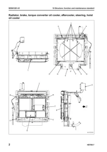
IMAGES PREVIEW
Delivered as an instant-download PDF, the manual arrives the moment payment clears. No shipping, no waiting, no binder to lose. Read it on a laptop in the cab, a tablet on the bench or a phone beside the machine, and print only the pages you need for the job at hand.


Reviews
There are no reviews yet.