Description
Atlas Copco DM30 II Blasthole Drill Instruction Manual – Revision 005
This is the full Atlas Copco DM30 II Instruction Manual, Revision 005, published April 2017 by Atlas Copco (Nanjing) Construction and Mining Equipment Ltd. It is the complete reference document for anyone who operates, maintains, or troubleshoots the DM30 II crawler-mounted hydraulic tophoad blasthole drill. The manual walks through every major system on the machine, from the diesel engine and asymmetrical rotary screw compressor to the hydraulic propel circuit, feed circuit, rotation circuit, and the auxiliary 14-spool valve assembly. Every maintenance interval from the 8-10 hour daily check to the 6000-hour coolant service is laid out with the procedures, torque values, and fluid capacities required to keep the rig running safely.
File Details
- Manual Type: Instruction Manual (Operation, Safety, Maintenance, Troubleshooting)
- Brand: Atlas Copco
- Model: DM30 II Blasthole Drill
- Manufacturer: Atlas Copco (Nanjing) Construction and Mining Equipment Ltd., Nanjing, China
- Revision: 005
- Revision Date: April 2017
- Language: English
- Format: PDF
- Page Count: 520 pages
Chapters Covered in the DM30 II Instruction Manual
The manual is organized into eight numbered sections plus a revision history and glossary. The full contents as printed include:
- Section 1 – Introduction: General information, how the manual is organized, receiving the drill, identification data, drill and engine identification, drill description, major components
- Section 2 – Safety: Safety and health statement, safety precautions and guidelines, designated and non-designated applications, equipment safety rules, operation safety, electrical power line safety, drilling safety, tramming safety, stopping and shutdown safety, sliding fork warnings, rotary head and carousel warnings, maintenance safety, fueling, batteries, wire rope and cable, hydraulic maintenance safety, cylinder repairs, pumps and motors, valves, hoses, coolers and fans, guards, tracks, lubrication, compressor safety, overhead electric wires, ventilation, grade limitations, transportation safety, towing safety, safety decals list and locations, hazardous substance precautions, symbol identification
- Section 3 – Specifications: General description, drill applications, design features, environment rate factor ranges, operational limitations, ambient temperature range, ground pressure, maximum allowable slope angle, stability conditions, sound and vibration exposure limits, DM30 II stability/gradeability charts, standard equipment and specifications, main frame and leveling jacks, undercarriage and propel system, tower, carousel and drill pipe handling, rotary head, carriage feed system, power pack, air compressor, hydraulic system, operator’s cab and controls, night lights, optional equipment, angle drill package, dust collector, water injection, central service system, cold weather options, DHD injection lube, standard tools and manuals, operational weights and dimensions
- Section 4 – Operating Controls: Operator’s console layout, drill functions panel, gauges functions panel, engine functions panel, compressor functions panel, propel functions panel, controls and instruments not located on console panels
- Section 5 – Operating Instructions: Walk around inspection, pre-start inspection, engine operation, starting and stopping hints, compressor operation, propel operation, drill setup, leveling, tower raising and locking, tower lowering, overpressure control system, carousel and drill pipe handling, drill pipe loading, field replacement, adding drill pipe, removing drill pipe, tricone drilling procedures, DTH drilling procedures, angle drilling, stopping, parking and shutdown, towing, special conditions of use, preservation and storage
- Section 6 – Maintenance: Maintenance safety, maintenance schedule, fluids and refill capacities, maintenance as required, 8-10 hour daily maintenance, 50 hour weekly maintenance, 100 hour maintenance, 150 hour maintenance, 250 hour maintenance, 500 hour maintenance, 1000 hour maintenance, 1500 hour maintenance, 2000 hour maintenance, 5000 hour maintenance, 6000 hour maintenance, torque specifications
- Section 7 – System & Troubleshooting: Electrical system, operator observed problems, pneumatic system, hydraulic system, auxiliary function circuit, electro hydraulic system, dust collector troubleshooting, Centro-Matic electric lube troubleshooting, Centro-Matic air lube troubleshooting, Dixon Boss clamp selection and installation
- Glossary: Definitions of drilling, hydraulic, electrical, and machine terms used throughout the manual
Complete PDF Bookmark Tree
Complete Bookmarks
The complete bookmarks in the “Atlas Copco DM30 II Blasthole Drill Instruction Manual Rev 005 – PDF Download” are as follows:
Atlas Copco Drilling Solutionsp. 1
Instruction Manual Original Instructionsp. 1
MODEL: DM30 IIp. 1
Revision 005p. 1
+Section 1 – Introductionp. 19
+INTRODUCTIONp. 20
General Informationp. 20
+How this manual is organizedp. 21
Where to find informationp. 21
Procedure When Receiving Drillp. 23
+Identification Datap. 23
Drill Identificationp. 24
Engine Identificationp. 24
Instruction Manual Locationp. 25
+Drill Descriptionp. 25
Enginep. 25
Main Framep. 26
Drill Towerp. 26
Operator’s Cab and Controlsp. 26
Power packp. 26
Tramming (Propelling)p. 26
Serviceabilityp. 26
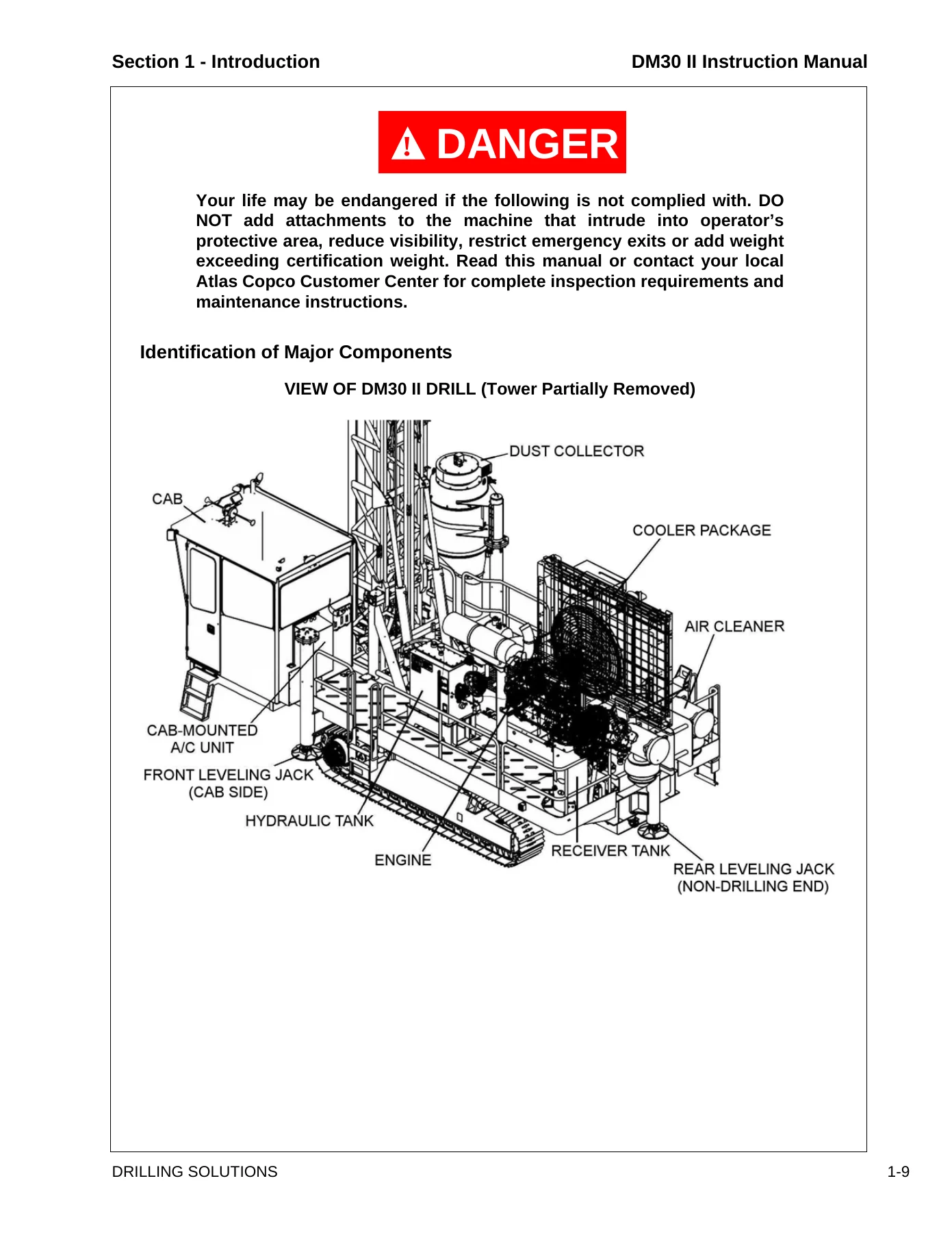
Identification of Major Componentsp. 27
+Section 2 – Safetyp. 29
+2.1 – SAFETY AND HEALTHp. 30
General Safety and Healthp. 30
Safety and Health Statementp. 30
Emergenciesp. 31
Important Safety Instructionsp. 31
+2.2 – SAFETY PRECAUTIONS AND GUIDELINESp. 32
Overviewp. 32
Important Safety Instructionsp. 32
Warningsp. 33
+Drill Applicationsp. 34
Designated Applicationsp. 34
Non-Designated Applicationsp. 34
Safety Reminderp. 35
Qualify Your Personnelp. 35
General Guidelinesp. 36
Equipment Safety Rulesp. 38
Pre-Start Inspectionp. 41
+Operation Safetyp. 41
Safety Instructions Governing Operationp. 41
Setup and Startp. 42
Electrical Power Line Safetyp. 43
Operating Safetyp. 44
Drilling Safetyp. 45
Propelling (Tramming) Safetyp. 45
Stopping and Shutdown Safetyp. 46
Sliding Forkp. 47
Special Warnings for Rotary Head and Carouselp. 47
+Maintenance Safetyp. 48
Fuelingp. 50
Batteriesp. 50
Wire Rope & Cablep. 51
+Hydraulic Maintenance Safetyp. 52
Cylinder Repairs or Replacementp. 52
Pumps and Motorsp. 52
Valvesp. 52
Hosesp. 53
Coolers and Fansp. 53
Guardsp. 53
Tracksp. 53
Lubricationp. 54
Compressorp. 54
+Warning of Special Dangersp. 55
Overhead Electric Wiresp. 55
Ventilationp. 55
Grade Limitationsp. 55
+Transportation Safetyp. 56
Safety Precautionsp. 56
Towing Safetyp. 57
+2.3 – SAFETY DECALS & NAMEPLATESp. 58
Safety Decals Listp. 58
Safety Decals & Nameplatesp. 61
+2.4 – HAZARDOUS SUBSTANCE PRECAUTIONp. 76
2.5 – SYMBOL IDENTIFICATIONp. 77
+Section 3 – Specificationsp. 83
+SPECIFICATIONSp. 84
General Descriptionp. 84
+Drill Applicationsp. 84
Designated Applicationsp. 85
Non-Designated Applicationsp. 85
Design Featuresp. 85
+Environment Rate Factor Rangesp. 87
Duty:p. 87
Ambient Temperature:p. 87
Service:p. 87
Application Type:p. 87
+Operational Limitationsp. 88
Ambient Temperature Rangep. 88
Ground Pressurep. 88
Maximum Allowable Slope Anglep. 88
Operating Conditions for Stabilityp. 88
Sound Pressure Limitations (EEC Requirement)p. 88
Vibration Exposure Limitations (EEC Requirement)p. 88
DM30 II Blasthole Stability/Gradeability Chartp. 89
+Standard Equipment and Specificationsp. 90
Main Frame and Leveling Jacksp. 91
Undercarriage and Propel Systemp. 91
Tower, Carousel and Drill Pipe Handlingp. 92
Rotary Headp. 93
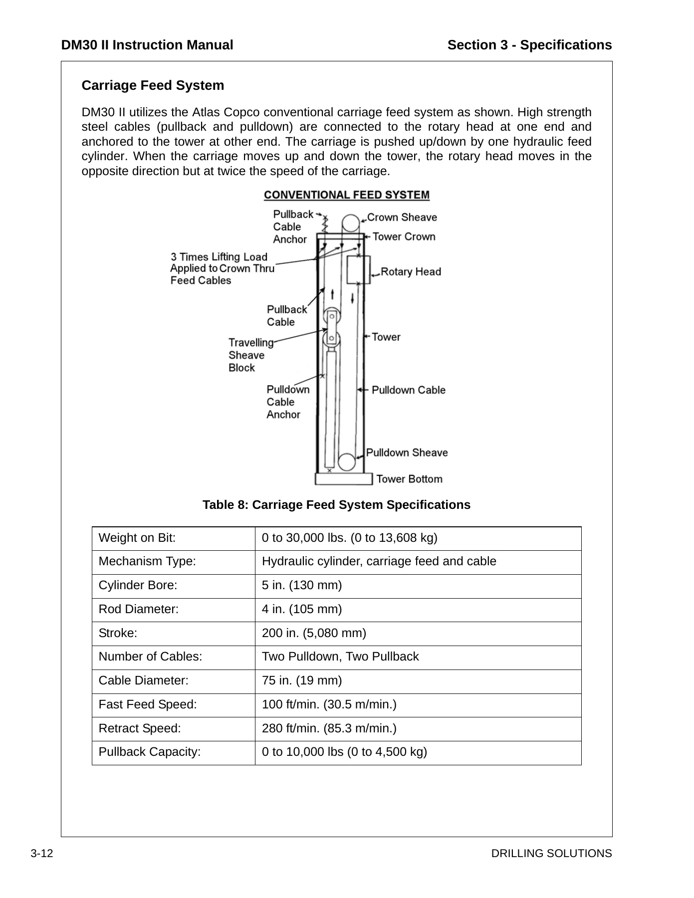
Carriage Feed Systemp. 94
Power Packp. 95
Air Compressorp. 95
Hydraulic Systemp. 96
Operator’s Cab and Controlsp. 97
Night Lightsp. 98
+Optional Equipmentp. 98
Air Conditioner / Heater Package – Cab-Roof Mountedp. 98
Angle Drill Packagep. 98
Dust Control, Dust Collector (Dry)p. 99
Dust Control, Water Injection (Wet)p. 99
Central Service Systemp. 99
Cold Weather Optionsp. 99
DHD Injection Lube (for HP Drill)p. 100
+Optional Accessoriesp. 100
Floating Cushion Shock Subp. 100
Ball Bearing Roller Deck Bushingp. 100
Standard Tools And Manualsp. 100
Operational Weights And Dimensionsp. 101
+Section 4 – Operating Controlsp. 103
+OPERATING CONTROLSp. 104
+General Informationp. 104
+Operator’s Consolep. 105
Panel – Drill Functionsp. 106
Panel – Gauges Functionsp. 108
Panel – Engine Functionsp. 109
Panel – Compressor Functionsp. 115
Panel – Propel Functionsp. 116
Controls and Instruments Not Located on Console Panelsp. 120
+Section 5 – Operating Instructionsp. 123
+OPERATING INSTRUCTIONSp. 124
+General Informationp. 124
+Walk Around Inspectionp. 125
Check for Hydraulic System Oil Leaksp. 125
Check for Compressor System Oil Leaksp. 125
Check for Coolant System Leaksp. 125
Check for Fuel System Leaksp. 126
General Checksp. 126
Operator’s Areasp. 126
+Pre-Start Inspectionp. 126
Check Engine Oil Levelp. 127
Check Engine Coolant Levelp. 127
Check Fuel System Levelp. 128
Drain Fuel Filter / Water Separatorp. 128
Check Compressor Oil Levelp. 128
Drain Receiver Tank Waterp. 129
Check Ball Valve in the Pressure Air Line (Only for High Altitude Model)p. 129
Check the Batteriesp. 129
Pump Drive Gearbox Oil Levelp. 129
Check Hydraulic Oil Levelp. 130
Keep Operator’s Areas Cleanp. 131
Pre-Operation Controls Inspectionp. 131
Warning Controls Checkp. 132
+Engine Operationp. 134
Engine Starting Procedurep. 135
Starting Enginep. 136
Ether Cold Start (option)p. 137
Verify Gauges & Controlsp. 137
Engine Speed controlp. 138
Water Temperature Gaugep. 138
Stopping Enginep. 138
+Emergency Shutdownp. 139
Emergency Shutdown Initiationp. 139
Starting and Stopping Hintsp. 140
+Compressor Operationp. 141
Start/Run/Stop Proceduresp. 141
Start Positionp. 141
Run Positionp. 141
Stop Positionp. 141
+Propel Operationp. 142
Recommendations and Checksp. 142
Propel Alarm Check Procedurep. 142
Hydrostatic Brake System Check Procedurep. 142
Propel (Tram) the Drillp. 143
Stopping Drill Propelp. 144
+Drill Setupp. 145
Drill Setup Controlsp. 145
Prepare Drill and Areap. 146
Leveling The Drillp. 146
Tower Raisingp. 147
Tower Lockingp. 147
Tower Loweringp. 148
Overpressure Control Systemp. 148
Overpressure System Testp. 149
+Carousel and Drill Pipe Handlingp. 150
DM30 II Carouselp. 150
Set-up Drill for Initial Carousel Loadingp. 151
Carousel Operating Procedurep. 152
+Drill Pipe Handlingp. 153
Drill Pipe Loadingp. 153
Initial Drill Pipe Loadingp. 154
Drill Pipe Field Replacementp. 157
Adding Drill Pipe Proceduresp. 158
Adding Drill Pipe to Drill Stringp. 159
Remove Drill Pipe from Drill Stringp. 160
+Tricone Drilling Procedures (for LP Drill)p. 162
Introduction on Tricone Drillingp. 162
Tricone Drill String Tools and Accessoriesp. 162
Starter Pipe/Stabilizer Installation Procedurep. 164
Tricone Bit Installation Procedurep. 165
Tricone Drilling Procedurep. 165
Tricone Bit Changing Procedurep. 166
Chain Wrenchp. 167
+DTH Drilling Procedures (for HP Drill)p. 168
Introduction on DTH Drillingp. 168
DTH Drill String Tools and Accessoriesp. 168
DTH Drilling Processesp. 169
DTH Hammer Installationp. 170
DTH Button Bit Installationp. 171
Install DTH Hammer to Drill Pipep. 172
Start the Hole with a DTH Drillp. 174
DTH Drilling Procedurep. 175
Bit Removalp. 175
Remove Bit from DTH Hammerp. 176
Remove DTH Hammer from Drill Stringp. 176
General Drilling Hintsp. 177
+Angle Drillingp. 178
General Informationp. 178
+Stopping, Parking & Shutdownp. 180
Stopping the Drillp. 180
Parking the Drillp. 180
Normal Shutdownp. 181
Emergency Shutdownp. 182
Daily Precautions After Workp. 182
Mounting and Dismounting of Equipment and Attachmentsp. 182
Towing the Drillp. 182
+Special Conditions of Usep. 183
Cold Weather Conditionsp. 183
Hot Weather Conditionsp. 183
Water and Muddy Conditionsp. 183
Dusty Conditionsp. 183
High Altitude Conditionsp. 183
Preservation & Storagep. 183
+Section 6 – Maintenancep. 185
+6.1 MAINTENANCE SAFETYp. 186
+Maintenance Safety and Healthp. 186
Safety Precautionsp. 187
Fluid Penetrationp. 187
Lines, Tubes and Hosesp. 187
Burn Preventionp. 188
Coolantp. 188
Oilsp. 189
Batteriesp. 189
Fire or Explosion Preventionp. 189
Fire Extinguisherp. 191
Crushing or Cutting Preventionp. 191
Mounting and Dismountingp. 191
Before Starting the Enginep. 192
Engine Startingp. 192
Starting Aidsp. 193
Engine Stoppingp. 193
+Maintenance Informationp. 194
Handling Fluids and Oilp. 195
+6.2 MAINTENANCE SCHEDULEp. 196
Maintenance Schedule Informationp. 196
+6.3 FLUIDS AND REFILL CAPACITIESp. 202
Hazardous Substance Precautionp. 202
General Informationp. 203
Lubrication Chartp. 204
Refill Capacitiesp. 206
+6.4 MAINTENANCE AS REQUIREDp. 207
General Informationp. 207
Service As Requiredp. 208
+Air Cleanerp. 208
Air Cleaner Indicatorsp. 209
Connections and Ductsp. 209
Empty Dust Cupsp. 210
Air Cleaner Pre-Cleanerp. 211
Air Cleaner Rain Guardp. 211
Air Cleaner Elementsp. 212
Air Cleaner Service Tipsp. 215
Clean The Drillp. 216
Loose Bolted Connectionsp. 216
+Feed Cable & Wire Ropep. 217
Replacement Guidelinep. 217
Cable Lubricationp. 218
Feed Cable Replacementp. 218
Wire Ropep. 218
Wire Rope Clampsp. 219
Wire Rope Installationp. 221
+Grease Drum Optionp. 222
Carousel Lock Platep. 223
+6.5 MAINTENANCE (8-10 Hours)p. 224
General Informationp. 224
Overpressure System Testp. 225
+Air Cleanersp. 226
Air Cleaner Indicatorsp. 226
Connections and Ductsp. 227
Empty Dust Cupsp. 227
Air Hose and Clampsp. 228
+Enginep. 229
+Engine Belts & Tensionerp. 230
Drive Belts Inspectionp. 230
Belt Replacementp. 231
+Engine Beltsp. 232
+Engine Fuel / Water Separatorsp. 233
Fuel / Water Separatorp. 233
+Cooling System Maintenancep. 234
Radiator Coolant Levelp. 234
Cooling System Sealing Additivesp. 236
Cooling System Soluble Oilsp. 236
Clean Radiator and Oil Coolersp. 236
+Fuel Tankp. 238
+Receiver Separatorp. 239
Drain Water from Receiver Tankp. 239
Compressor Oil Levelp. 240
Oil Carry Overp. 240
Change Receiver Separator Elementp. 240
+Hydraulic Reservoirp. 243
Hydraulic Oil Levelp. 243
Hydraulic Oil Filtersp. 245
+Rotary Headp. 246
Rotary Head Oil Levelp. 246
Rotary Head Upper Bearingp. 247
+Gearbox Driveshaftp. 247
Grease Gearbox Drive Shaft Universal Jointsp. 247
+Dust Collectorp. 248
Dropout Hosep. 248
Suction Hosep. 248
Blower Assemblyp. 248
Filter Elementsp. 249
Pipe Sealp. 249
+Housekeepingp. 250
Clean the Drillp. 250
Loose Bolted Connectionsp. 250
+6.6 MAINTENANCE (50 Hours or Weekly)p. 251
General Informationp. 251
+Batteriesp. 253
Electrolyte Levelp. 253
Battery Terminalsp. 253
+Pump Drive Gearboxp. 254
Oil Leaksp. 254
Check Oil Levelp. 254
+Undercarriagep. 255
Initial Break-In Maintenancep. 255
Final Drive Mounting Boltsp. 255
Oil Leaksp. 256
Oil Level – Final Drivep. 256
+Tracksp. 257
Track Tensionp. 257
Track Adjustmentp. 258
+Auxiliary Hoistp. 259
Periodic Inspectionp. 260
Wire Ropep. 260
+6.7 MAINTENANCE (100 Hours)p. 261
General Informationp. 261
+Auxiliary Hoistp. 263
Oil Changep. 263
Mounting Boltsp. 264
+6.8 MAINTENANCE (150 Hours)p. 265
General Informationp. 265
+Track Planetary Gearboxp. 267
Final Drive Mounting Boltsp. 267
Change Initial Track Planetary Oilp. 267
+6.9 MAINTENANCE (250 Hours)p. 269
General Informationp. 269
Engine Maintenancep. 271
+Engine Lubricating Oil and Filtersp. 271
Drain Engine Oilp. 272
Replace Engine Oil Filter(s)p. 272
Fill Engine Crankcasep. 274
Secondary Fuel Filter(s)p. 275
Coolant Filterp. 277
Engine SCA Levelp. 277
Engine Valve Lashp. 278
+Auxiliary Hoistp. 279
Wire Rope Conditionp. 279
+6.10 MAINTENANCE (500 Hours)p. 280
General Informationp. 280
+Batteriesp. 282
Batteries, clamps and Cablesp. 282
+Fuel Tankp. 282
+Hydraulic Reservoirp. 283
Hydraulic Tank Breathersp. 283
Hydraulic Fluid Condition Limitsp. 283
Change Hydraulic Oilp. 284
Drain Hydraulic Reservoirp. 284
Refill Hydraulic Reservoirp. 285
+Compressorp. 287
Compressor Oil Strainerp. 287
Compressor Oil Filterp. 288
+Pump Drive Gearboxp. 289
+Auxiliary Hoistp. 290
Check Oil Levelp. 290
Cable/Rope Lubricationp. 291
+Compressor Air Hose and Clampsp. 291
+6.11 MAINTENANCE (1000 Hours)p. 292
General Informationp. 292
+Compressor Oilp. 294
Change Compressor Oilp. 294
Change Compressor Oil Filterp. 295
+Hydraulic Oil Filtersp. 296
Replace Hydraulic Return Filtersp. 297
Replace Hydraulic Drain Filterp. 298
+Rotary Headp. 299
Change Rotary Head Oilp. 299
+Pump Drive Gearboxp. 301
+Auxiliary Hoistp. 302
Oil Changep. 302
Mounting Boltsp. 303
+Carouselp. 304
+6.12 MAINTENANCE (1500 Hours)p. 305
General Informationp. 305
+Track Planetary Gearboxp. 307
Change Initial Track Planetary Oilp. 307
+6.13 MAINTENANCE (2000 Hours)p. 309
General Informationp. 309
+Air Cleanersp. 311
Primary and Safety Elementsp. 311
Compressor Discharge Hosep. 312
Engine Belts and Tensionerp. 312
+6.14 MAINTENANCE (5000 Hours)p. 313
General Informationp. 313
+Hydraulic Reservoirp. 315
Change Hydraulic Oilp. 315
Drain Hydraulic Reservoirp. 315
Refill Hydraulic Reservoirp. 316
+6.15 MAINTENANCE (6000 Hours)p. 318
General Informationp. 318
+Engine Coolantp. 320
Drain Cooling systemp. 321
Flush Cooling Systemp. 322
Fill the Cooling Systemp. 323
+6.16 Torque Specificationsp. 324
+Standard Torque Valuesp. 324
General Informationp. 324
Head Markingsp. 324
Recommended Torques in Foot Pounds (ft/lbs.)p. 325
Recommended Torques in Nmp. 326
+Section 7 – System & Troubleshootingp. 329
+7.1 SYSTEM & TROUBLESHOOTINGp. 330
Overviewp. 330
Electrical Systemp. 331
Operator Observed Problemsp. 331
Pneumatic Systemp. 331
Hydraulic Systemp. 331
Enginep. 331
+7.2 ELECTRICAL SYSTEMp. 332
General Informationp. 332
Electrical System Informationp. 333
+Enginep. 333
Batteriesp. 334
Fusible Linksp. 335
Starter Motorp. 335
Alternatorp. 336
Key Switchp. 336
Circuit Breakersp. 337
Push buttonsp. 337
Engine Shutdown devicesp. 337
Compressor Discharge Temperature Switch (ECM protects Later Engines)p. 337
Engine Electronicsp. 338
+Indicator Light system (Option)p. 339
Red Indicator Lightp. 339
Yellow Indicator Lightp. 339
White/Blue Indicator Lightp. 340
Diagnostic Fault Codesp. 340
Diagnostic Switchp. 340
Incremental Switchp. 340
Finding Fault Codesp. 340
Reading fault codesp. 341
Fault Code Examplep. 342
+Caterpillar Engine Diagnostic Codesp. 343
Event Codesp. 346
Fault Loggingp. 347
Engine Operation with Active Diagnostic Codesp. 347
Engine Operation with Intermittent Diagnostic Codesp. 347
Cummins Fault Code Tablesp. 348
+MurphyLink Powerview Systemp. 353
Descriptionp. 354
Faceplate Features and Keypad Functionsp. 355
Mechanical Installationp. 356
Electrical Installationp. 356
First Time Start Upp. 357
Main Menu Navigationp. 357
+Main Menu Optionsp. 358
Select a Languagep. 358
Stored Codesp. 359
Engine Configurationp. 360
Setup 1-Up Displayp. 361
Setup 4-Up Displayp. 362
Select Unitsp. 363
BackLight Adjustmentp. 363
Contrast Adjustmentp. 364
Utilities (Information and Troubleshooting)p. 364
MODBUS Setupp. 365
+Faults and Warningsp. 368
Auxiliary Gage Faultp. 368
Active Fault Codesp. 368
Shutdown Codesp. 369
Faults Diagnosis for PowerViewp. 370
Electric Ladderp. 371
Electrical Symbolsp. 373
+7.3 OPERATOR OBSERVED PROBLEMSp. 374
Operator Observed Problemsp. 374
+7.4 PNEUMATIC SYSTEMp. 377
+Pneumatic System Informationp. 378
Adjustment of the Pneumatic Regulating Systemp. 378
Compressor Fire Preventionp. 379
+Lubrication Systemp. 380
+Lubrication System Componentsp. 380
Receiver – Separator Tankp. 380
Strainerp. 381
Thermostatic Valvep. 381
Oil Coolerp. 382
Oil Filterp. 382
Discharge Check Valvep. 383
Compressor Oilp. 383
Oil Flowp. 383
+Separation Systemp. 385
+Regulation Systemp. 387
Discharge Check Valvep. 388
Blowdown Valvep. 389
Receiver Tankp. 389
Minimum Pressure Valvep. 390
Safety Relief Valvep. 390
Service Connectionp. 391
Receiver Tank Pressure Gaugep. 391
Compressor Related Problemsp. 392
+7.5 HYDRAULIC SYSTEMp. 393
Introductionp. 393
+Propel Circuitp. 393
Componentsp. 394
Main Hydraulic Pumpsp. 394
Propel Motorsp. 396
Propel Motor Brakep. 396
Diverter Valve Assemblyp. 397
Propel/Drill Mode Selectorp. 397
Drill/Propel Control Valvep. 398
Loop Filling/Replenishmentp. 399
Loop Flushing Circuitp. 400
Circuit Operationp. 401
Oil Path Selectionp. 404
+Feed Circuitp. 405
Mechanical Componentsp. 405
Hydraulic Componentsp. 405
Feedp. 407
Feed Pump (CS Main Pump)p. 407
Feed Cylindersp. 408
Feed Carriagep. 408
Over center Valvep. 409
Pressure Control Valvep. 409
Two-Way Valvep. 409
Diverter Valve Assemblyp. 409
Drill/Propel Control Valvep. 409
Remote Compensator Controlp. 410
Jack Two-Way Valvesp. 410
Over Pressure Controlp. 411
Over Pressure System Testp. 411
Feed Circuit Operationp. 412
Oil Path Selectionp. 412
Cylinder Extend and Retractp. 412
Loop filling/Replenishmentp. 413
+Rotation Circuitp. 414
Main Pumpp. 416
Rotation Motorsp. 416
Rotation Motor Displacement Adjustmentp. 417
Rotation Motor Control Valvep. 418
Rotation Circuit Operationp. 418
Rotationp. 418
Motor Displacement Controlp. 419
Drill/Propel Control Valvep. 419
Oil Path Selectionp. 419
Loop Filling / Replenishmentp. 420
+7.6 AUXILIARY FUNCTION CIRCUITp. 421
+Componentsp. 421
Double Pumpp. 421
Motorsp. 422
Cylindersp. 422
Relief Valvesp. 423
Check Valvesp. 423
Two Way Valvep. 423
Holding Valvesp. 424
Pilot Check Valvesp. 424
+Manifold Systemp. 425
Return Manifoldp. 427
Supercharge Manifoldp. 427
Drain Manifoldp. 427
Filter Assemblyp. 427
+Hydraulic Reservoir Systemp. 428
Circuit Operation of Manifold and Hydraulic Reservoirp. 428
+P1 Pump Circuitp. 429
+Cooling Circuitp. 430
Fan Motorp. 430
Circuit Operationp. 430
+P2 Pump Circuitp. 431
14-Spool Valvep. 432
Circuit Operationp. 436
+Service Notesp. 437
Pressure Test Portsp. 437
Fluid Samplingp. 437
Hydraulic Connectionsp. 437
+7.7 ELECTRO HYDRAULIC SYSTEMp. 438
Overviewp. 438
+General Concepts and Terminologyp. 439
Current Controlp. 439
Pulse Width Modulationp. 439
Thresholdp. 440
Maximum Outp. 440
Dual Rangep. 440
Single Coil Controllersp. 440
Dual Coil Controllersp. 440
+Denison 900 Strokerp. 441
Adjustment Procedure for 9A Controls on a Goldcup Pumpp. 443
+Valvesp. 444
Apitech Pulsarsp. 444
14-Spool Valvep. 444
Holding Valvep. 445
+Controllersp. 446
Pulldown Controllerp. 446
Water Injection Rotary Activated Controllerp. 446
Limit Switchesp. 447
+Relaysp. 448
DPDT 24 VDC Relayp. 448
Typical Coil Resistancep. 448
Denison Stroker Coilp. 449
Apitech Coilsp. 449
Fema Coilsp. 449
Proportional Remote Control Outputp. 449
Checking Relayp. 450
Checking Limit Switchp. 450
Checking Diodep. 450
+EHC Operationp. 451
Jack Controllersp. 451
Hoist Controllerp. 451
Tower Raising Controllerp. 452
Pipe Indexer Controllerp. 452
Breakout Fork Wrench Controllerp. 452
Carousel Swing Controllerp. 452
Water Injection Controllerp. 453
Dust Collectorp. 453
Tower Pinningp. 453
Drill Propel Valvep. 454
Drill Feed Circuitp. 454
Rotation Controlp. 455
Drill Feed and Rotation Controllerp. 455
Drill Feed Force / No Bump Pipe Changer (Option)p. 456
Rotation Controlp. 457
Torque Limit Control (Option)p. 458
+EHC Adjustmentsp. 459
Feed and Rotation Controllersp. 459
Main Pump Controller Setting – Feed and Rotation (Drill) Controlsp. 460
Main Pump Controller Settings – Propel Controlsp. 461
Auxiliary Function Controllersp. 461
Pulldown Force Rotary Controllerp. 463
+7.8 TROUBLESHOOTING FOR DUST COLLECTORp. 464
Upper Tap HIGH – Lower Tap LOWp. 465
Upper Tap HIGH – Lower Tap HIGHp. 465
Upper Tap LOW – Lower Tap LOWp. 465
Dust Collector Trouble Shooting Guidep. 466
Excess Dustp. 466
Fan Dustp. 467
Pulsep. 467
Setting the Electric Timerp. 468
+7.9 TROUBLESHOOTING FOR CENTRO-MATIC ELECTRIC LUBEp. 469
General Informationp. 469
Principle of Operationp. 469
Fill Supply Linep. 470
Prime Feed Linesp. 470
Operation Checkp. 470
Troubleshooting for Electric Lubrication Pumpp. 471
+7.10 TROUBLESHOOTING FOR CENTRO-MATIC AIR LUBEp. 473
General Informationp. 473
Principle of Operationp. 473
Typical System Drawingp. 474
Fill Supply Linep. 475
Prime Feed Linesp. 475
Operation Checkp. 475
Attach Air Motor to Pump Tubep. 476
Failures without Alarm Systemsp. 477
Failures with Alarm Systemsp. 478
+7.11 DIXON BOSS CLAMP SELECTION AND INSTALLATIONp. 479
+Safety Informationp. 479
+Safety Alert: Securing Hosesp. 479
DOsp. 479
DON’Tsp. 479
Clamping Examplesp. 479
MSHA (Mine Safety and Health Administration) Regulationsp. 480
S.T.A.M.P.E.D.p. 481
General Preparation Instructionsp. 483
Dixon Diameter Tape Proceduresp. 485
+Boss Clampsp. 488
Boss Clamp Selectionp. 491
Criteria For Sufficient Fit of a Boss Clampp. 492
Installation Of Boss 2 Bolt Clampp. 493
Installation Of Boss 4 Bolt Clampp. 494
Installation Of Boss 6 Bolt Clampp. 495
+Testingp. 497
Hydrostatic Testingp. 497
Electrical Continuity Testingp. 498
+Glossaryp. 499
+GLOSSARY OF TERMSp. 500
~A~p. 500
~B~p. 501
~C~p. 503
~D~p. 505
~F~p. 507
~G~p. 507
~H~p. 508
~I~p. 509
~J~p. 509
~K~p. 509
~L~p. 509
~M~p. 510
~O~p. 511
~P~p. 511
~R~p. 513
~S~p. 514
~T~p. 516
~U~p. 517
~W~p. 518
What This Atlas Copco DM30 II Instruction Manual Gives You
The DM30 II is a crawler-mounted, hydraulic tophoad drive, multi-pass rotary drill designed for production blasthole drilling on prepared benches. This manual is written for the people who run and service those machines. It covers the diesel engine and compressor package, the excavator-type undercarriage, the hydraulic pumps and motors, the rotary head and feed cylinder, the carousel pipe changer, and the tower raising and locking systems in complete detail. The safety section is extensive and specific to this model, covering everything from power line clearance distances to the special warnings for the sliding fork, rotary head, and carousel. The maintenance section is structured by hourly intervals, so a technician can open the book at the correct interval and find the procedures, torque values, fluid capacities, and adjustment specs for that service.
The troubleshooting section is one of the most practical parts of the manual. It walks through engine fault codes for both Caterpillar and Cummins engines, explains how to read the diagnostic lights on the operator’s console, and includes operator-observed problem charts that map symptoms to causes and corrections. The electrical section covers the 24-volt system, fusible links, starter motor, alternator, key switch, circuit breakers, and the ECM-controlled engine protection system. The hydraulic section explains the propel circuit, feed circuit, rotation circuit, and auxiliary function circuit with component-level descriptions of pumps, motors, valves, and manifolds.
Who This DM30 II Manual Is For
This Atlas Copco DM30 II manual is intended for drill operators, field service technicians, maintenance planners, and shop mechanics who work on DM30 II blasthole drills. It is also useful for site supervisors who need to understand the safety requirements and operating limits of the machine before putting it to work on a bench. The language is technical and assumes familiarity with diesel engines, hydraulic systems, and drilling equipment, but the step-by-step procedures are written so that a competent technician can follow them without additional training material.
Coverage of HP and LP Configurations
The manual covers both the high-pressure (HP) and low-pressure (LP) configurations of the DM30 II. The HP drill uses a two-stage compressor and a HI/LO pressure selector for DTH hammer drilling, while the LP drill uses a single-stage compressor for rotary tricone drilling. Differences between the two configurations are called out where they matter, including compressor operating pressures, oil types (PAROIL S xtreme for HP, PAROIL S for LP), and the specific procedures for tricone versus DTH drilling. The engine options covered are the Caterpillar C15 and the Cummins QSX 15, with horsepower ratings and RPM given for each.
Get the Complete DM30 II Instruction Manual as an Instant PDF Download
This Atlas Copco DM30 II Instruction Manual gives you the full factory documentation for the machine in a single PDF file. You can use it to perform scheduled maintenance correctly, diagnose engine and hydraulic faults, set up the drill for safe operation, and follow the manufacturer’s procedures for pipe handling, bit changes, and tower operations. Having the correct procedures and specifications on hand reduces the risk of damage to the drill and helps keep the job site safe. The file is delivered instantly after checkout with no shipping and no waiting. You can open it on a laptop, tablet, or smartphone in the shop or on the bench, and print the pages you need for the task at hand.


Reviews
There are no reviews yet.