
Atlas Copco FlexiROC D50 D55 D60 D65 Maintenance Manual 2023 – TIS0000034.005 PDF Download
Original price was: $39.95.$23.95Current price is: $23.95.
Complete 192-page maintenance manual for Atlas Copco FlexiROC D50, D55, D60 and D65 surface drill rigs. Document TIS0000034.005, dated 2023-03-09. Covers scheduled preventive maintenance, lubrication, adjustment, inspection and service procedures for every major system including boom, feed, compressor, hydraulic, diesel engine, track frames, reverse circulation and more.
Description
Atlas Copco FlexiROC D50 D55 D60 D65 Maintenance Manual
This is the complete maintenance manual for the Atlas Copco FlexiROC D50, FlexiROC D55, FlexiROC D60 and FlexiROC D65 surface drill rigs. Published under document number TIS0000034.005 and dated 2023-03-09, this 192-page PDF provides the full scheduled preventive maintenance program for the entire machine — from daily external washing and fire extinguisher checks through to 8000-hour component replacement intervals. Every task is tied to a maintenance schedule based on calendar time and diesel engine hours, making this the primary reference for any technician responsible for keeping a FlexiROC rig in reliable working order.
File Details
- Manual type: Maintenance Manual
- Brand / Publisher: Atlas Copco / Epiroc Rock Drills AB
- Models covered: FlexiROC D50, FlexiROC D55, FlexiROC D60, FlexiROC D65
- Document number: TIS0000034.005
- Date: 2023-03-09
- Language: English (en-US)
- Page count: 192
- File format: PDF
Chapters Covered
- Introduction — Safety First, Purpose of Maintenance Publication, Target Group, Feedback and Contact Information
- Maintenance Management — Maintenance Management and Hour Meters, Maintenance Records
- Specifications — Standard Tightening Torques Bolted Joints, Type Designation Signs for Ordering Spare Parts
- Maintenance Schedule — Calendar Time, Diesel Engine Hours First Service, Diesel Engine Hours
- General Machine Condition — Wash Machine Externally, Check Condition of Hatches and Locks, Examine Condition of Signs, Remove Ice Formations
- Firefighting Equipment — Check Fire Extinguishers, Loosen Up Powder, Check Fire Suppression System
- Operator Environment — Check Cab, Check Attachment of Cab, Replace Air Condition Main Air Filter, Pre-filter, Circulation Filters, Troubleshooting Air Conditioner
- Boom Unit — Check Boom C14, Lubricate Boom C14, Replace Boom Head on Boom C14, Check Boom C20, Lubricate Boom C20, Replace Boom Head on Boom C20
- Feed Unit — Safety Precautions, Suspended Load Hazard, Opening and Closing Feed Guard, Check and Adjust Tension of Feed Chain, Reset Tension Screw Travel, Protective Covers on Feed Beam, Chain Guide, Chain Feed, Lubricate Chain Feed, Sprocket Wheel, Lubricate Rod Handling (RHS 140 and RHS 102), Check Slide Pieces, Check and Replace Slide Rails, Check and Lubricate Breakout Table, Check Drill Rod Support, Replace Bearing Unit
- Lubrication System for Hammer — Check Lubricant Level in Tank, Hammer Lubrication Pump (HECL)
- Control System — Adjusting Percussion Pressure, Adjusting Low and High Drill Feed Pressure, Rotation Speed Adjustment, Thread Feed Speed and Thread Feed Pressure Adjustment, Adjusting Penetration Rate, Anti-Jamming Protection, Rotation Pressure Switch B134, Lubrication Settings, Recommended Lubricant, Bleeding HECL System
- Dust Collector — Check Dust Collector, Check Dust Collector Filters, Replace Dust Collector Filters, Adjusting Suction Capacity
- Hydraulic System — Safety Precautions, About Working on Hydraulic Components, Oil Sampling, Hydraulic Workshops, Replacing Hydraulic Hoses, Repairing Hydraulic Components, Hydraulic Oil Recommendation, Hydraulic Filters (Return Oil Filter, Breather Filter), Hydraulic Tank, Check Hydraulic Pump
- Diesel Engine — Safety Precautions, Check Engine Oil Level, Replace Engine Oil, Recommended Engine Oil, Air System, Fuel System, Belts, Replace Primary Fuel Filter on Engine Heater, Check Diesel Engine for Leakage, Check Ground Bolts, Check Diesel Engine at 2500/3000/4000 Engine Hours
- Cooling System — Check Coolant Level, Add Coolant, Clean Radiators, Replace Long-term Effective Coolant
- Electrical System — Safety Precautions, Check Emergency Stops, Check Work Lights, Check Battery, Battery Charging, Charge the Battery Using External 24-V Charger, Start with Auxiliary Battery, Check Electric Cabinet
- Compressor — Safety Precautions, Compressor Overview, Drain Condensate from Compressor Tank, Drain the Water Separator Filter, Replace Filter Element, Replace Separator Filter, Check Compressor Oil Level, Oil Change and Oil Filter Replacement, Flushing Air Compressor, Clean Oil Cooler, Check Compressor for Leakage, Check Safety Valve Pressure, Check Pressure Sensor B456, Checking Start Protection, Checking Minimum Charge Pressure, Check Compressor Intermediate Stage Pressure, Check Percussion Pressure, Clean Valve Block Restriction, Control System for Air Compressor, Troubleshooting Air Compressor, Recommended Oil for Two Stage Compressor, Check Air Filter, Change the Plastic Valve Inside the Compressor
- Track Frames — Check Tension of Crawler Tracks, Tightening Torques for Track Frames, Procedures for Checking Wear (Track Roller, Carrier Roller, Front Wheel, Drive Wheel, Track Shoe, Track Link Depth, Bushing, Track Chain Elongation), Check Track Frames, Lubricate Track Frames, Replace Oil on Traction Gears
- Water Mist System — Check Seals on Water Mist Pump, Fill Water Mist Tank, Drain the Water Mist System, Start Up Water Mist System from Dry, Clean Filter in Water Mist Tank
- Reverse Circulation — Air Swivel, Check Reverse Circulation Components, Lubricate Rotary Actuator, Lubricate Outlet Swivel, Check Deflectors, Check Discharge System, Check Inner Tubes, Replace Inner Tube, Check Cone Splitter, Check Cyclone, Check Blowdown Valve, Lubricate Outlet Swivel with Metzke Blowdown Valve
- Automatic Central Lubrication System CLS — Pause Time and Operating Time Settings, Lubrication Pump Safety Valve, Fill Lubricant, Test Central Lubrication System or Start Extra Lubrication
- Service Winch — Replace Winch Transmission Oil, Lubricate Disengagement Device, Adjusting Drum Brake
- Wire Rope Maintenance — Wire Rope Maintenance, Wire Rope Replacement, Unloading and Storing, Condition Before Installing, Wire Rope Installation, General Check for Wire Ropes (breaks, surface wear, corrosion, diameter, reduced elasticity, heat exposure, wire displacement, waviness, cracks, kinks, flattening, basket formation, core or strand protrusion, protruding wires, bends, heat or electric arcing damage)
- Welding — About Welding, CAN Bus System Disconnection before Welding
- Storage — Preparations Before Long-Term Storage, Restoring After Long-Term Storage, Inspection and Maintenance During Long-Term Storage
This FlexiROC D50 D55 D60 D65 maintenance manual is organized around a scheduled preventive maintenance philosophy. The maintenance management chapter explains that intervals supplement each other — a longer interval comprises tasks supplementary to those from a shorter interval — and that maintenance must be performed at the shortest applicable interval of the unit or function. The manual distinguishes between maintenance based on engine hour meter readings and calendar-based maintenance that applies to rubber components, lubricants at risk during standstills, pressure vessel corrosion, and environmental exposure.
The maintenance schedule itself is comprehensive. Calendar-time tasks include daily items such as washing the machine externally, checking hatches and locks, examining signs, checking fire extinguishers, checking the fire suppression system, checking lubricant level in the hammer lubrication tank, and checking coolant level. Daily tasks also include lubricating the air swivel, lubricating the outlet swivel, and lubricating the outlet swivel with Metzke blowdown valve. Biannual and every-fifth-year fire suppression checks are also specified. Diesel engine hour intervals are broken out at 10, 40, 50, 250, 500, 1000, 1500, 2000, 2500, 3000, 4000, 5000, 6000, 8000, and 20000 hours, with first-service items at 50 and 150 engine hours.
The Atlas Copco FlexiROC maintenance manual covers every major system on the rig in dedicated chapters. The boom unit chapter provides inspection and lubrication procedures for both the C14 and C20 boom configurations, including checking feed attachment play (2–4 mm), cylinder bracket bearing play (maximum 1 mm), and boom head mounting, plus step-by-step boom head replacement with heavy-object lifting warnings and a requirement that only authorized personnel perform the task following Standard Operating Procedures. The feed unit chapter is especially detailed, covering feed chain tension checking and adjustment with a guiding principle of 2% sag for correct tension and 3% sag as time to discard, resetting tension screw travel, sprocket wheel inspection and lubrication (replace every third chain change), rod handling lubrication for RHS 140 (17 grease nipples) and RHS 102, slide piece replacement with a wear allowance rule that if any slide piece wear allowance is less than 1 mm all must be replaced, slide rail replacement with sharp-edge warnings and a requirement to bevel facing edges to 45 degrees, breakout table torque checks (adjustment screw lock nut 185 Nm, cylinder bracket 600 Nm, ball bearing clearance max 0.5 mm), and drill rod support torque checks (lock nut 185 Nm, cylinder bracket 120 Nm, slide piece thickness 4 mm).
Control system adjustment procedures are provided for percussion pressure (with model-specific recommended values: FlexiROC D50 and D60 at 27 bar high / 17 bar low, FlexiROC D55 and D65 at 32 bar high / 20 bar low), low drill feed pressure (factory set 60 bar), high drill feed pressure (factory set 120 bar), rotation speed with drill bit size and rock property guidelines, thread feed speed and pressure for both threading and unthreading, penetration rate via slide stop screws, and anti-jamming protection via rotation pressure switch B134 (factory set 80 bar, guide value about 15 bar above normal rotation pressure). The HECL bleeding procedure is also covered.
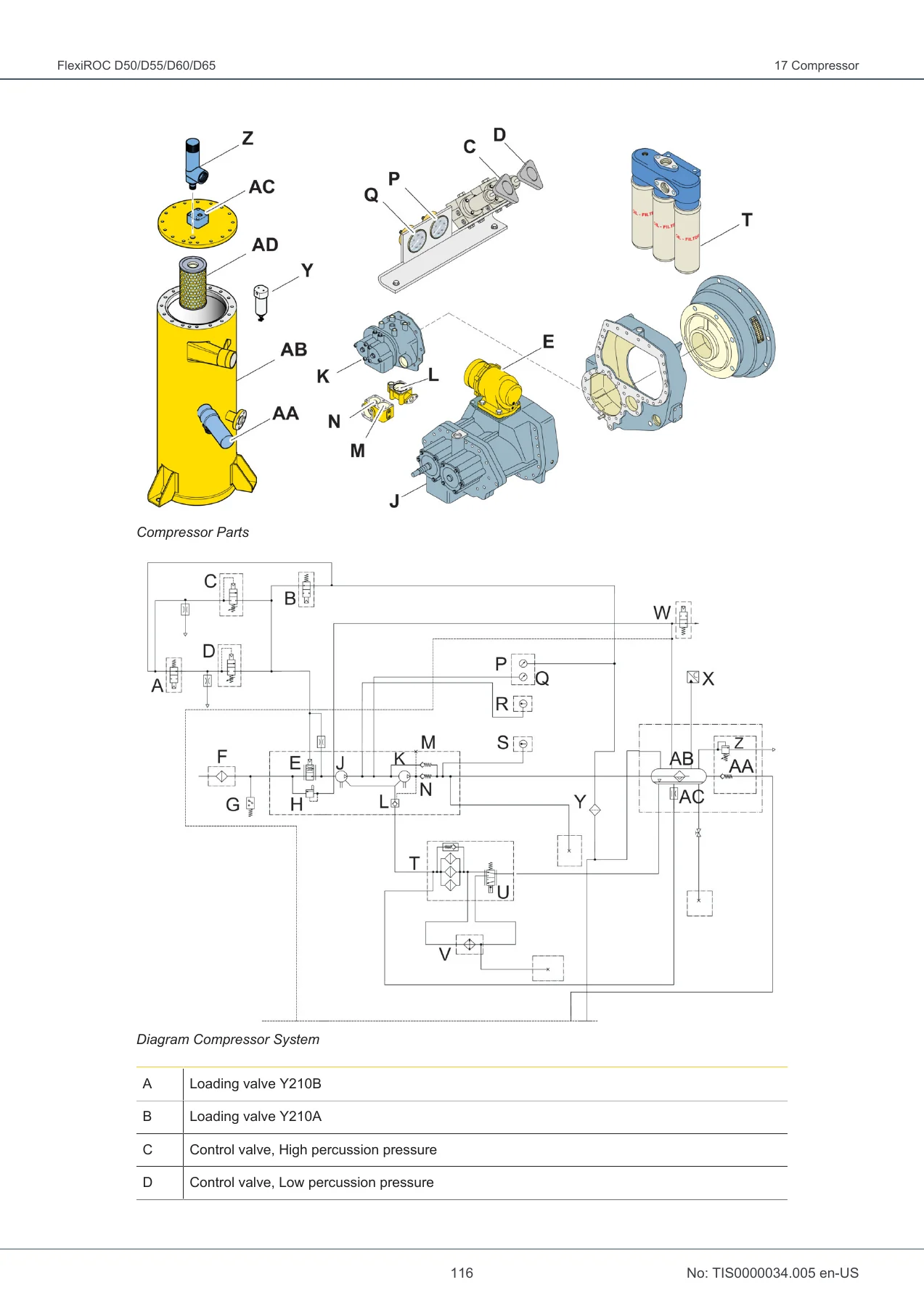
The compressor chapter provides extensive coverage of the two-stage screw compressor, including compressor overview with labeled exploded parts diagram and system diagram, daily condensate draining, water separator filter draining and element replacement, separator filter replacement, oil level checking, oil change and oil filter replacement with flushing procedure, oil cooler cleaning, leakage checks, safety valve pressure checking (maximum triggering pressure: FlexiROC D50 and D60 at 32 bar, FlexiROC D55 and D65 at 35 bar), pressure sensor B456 checking, start protection checking, minimum charge pressure checking (4 bar), intermediate stage pressure checking (unloaded 0.5–2 bar, loaded 5–6.5 bar), percussion pressure checking, valve block restriction cleaning, control system description, percussion pressure adjustment, and a detailed troubleshooting table covering symptoms such as compressor loaded automatically to full capacity after starting, compressor does not provide air, excessive oil consumption, compressor capacity or pressure below normal, diesel engine does not reach maximum engine speed, pressure in air receiver increases above maximum, air and oil mist emerge from air filters, compressor overheated, intermediate stage pressure below normal, and intermediate stage pressure above normal.
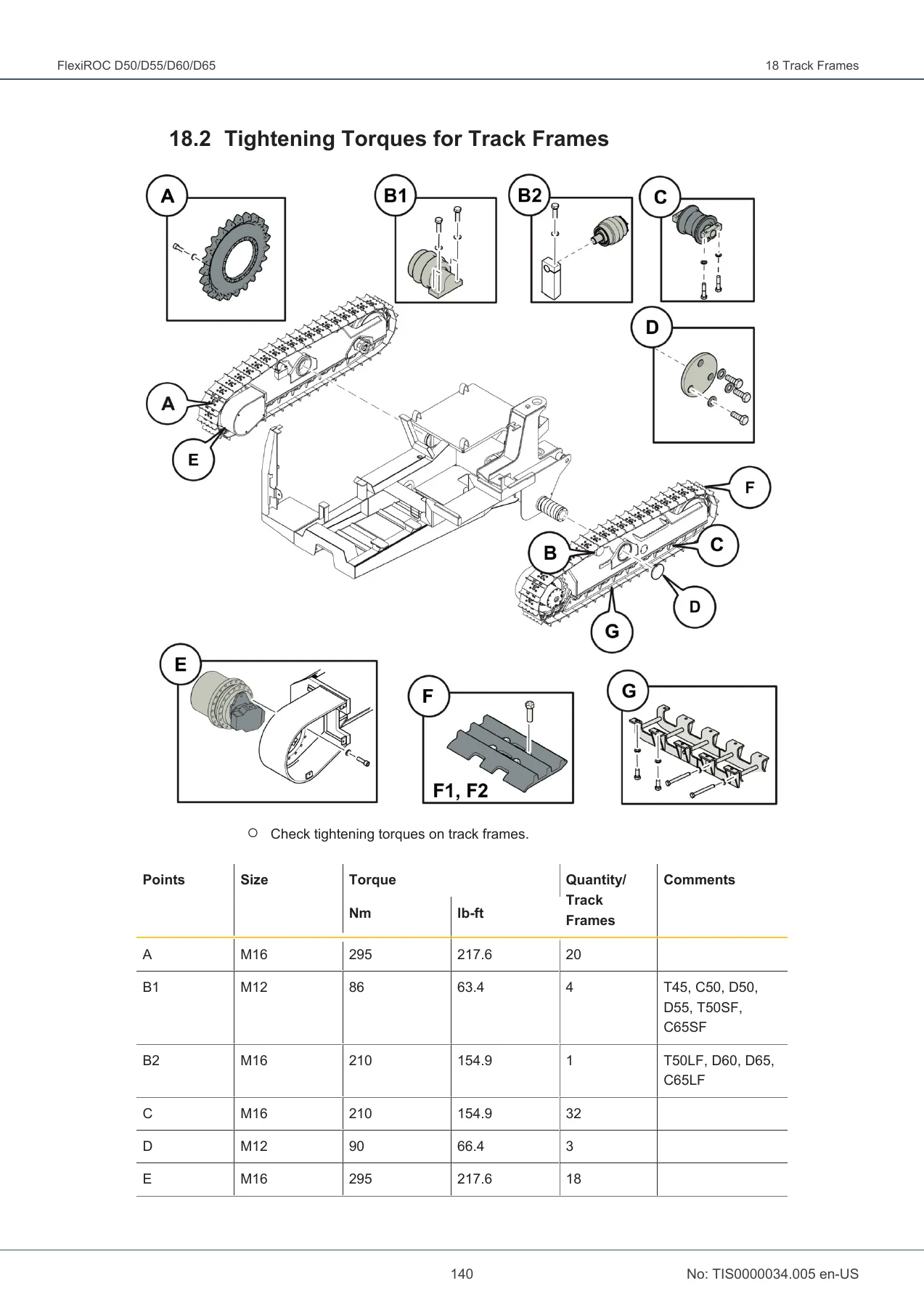
Track frame coverage includes crawler track tension checking with a clearance specification of 20–30 mm, tightening torques for track frame components (with specific values for M16, M12, and other fasteners), wear checking procedures for track rollers (new 155 mm / 17.5 mm, wear 100% at 149 mm / 21 mm), carrier rollers (new 100 mm / 7.5 mm, wear 100% at 92 mm / 11.5 mm), front wheels (new 17.5 mm, wear 100% at 25.5 mm), drive wheels, track shoes (new 25 mm, wear 100% at 11 mm), track link depth (B4: new 89 mm, wear 100% at 82 mm; FL6: new 83.0 mm, wear 100% at 75.7 mm), bushings (new 50.7 mm, wear 100% at 45.9 mm), and track chain elongation (new 686 mm, wear 100% at 698.7 mm), plus traction gear oil replacement with a 2-litre capacity and damper position check with a 50 mm slide block protrusion limit indicating chain replacement.
The reverse circulation chapter covers air swivel checking and lubrication, reverse circulation component checks, rotary actuator lubrication, outlet swivel lubrication, deflector checks including ceramic block and second deflector inspection, discharge system checks including sample hose and safety restraints, inner tube checks and replacement, cone splitter knife valve seal checking, cyclone wear plate checking, and blowdown valve inspection including hardened insert inside diameter limits (58–60 mm) and cylinder rod seal replacement if oil or air leaks from the indicator hole.
Wire rope maintenance is covered in exceptional detail with discard criteria for wire rope breaks (with a table of maximum permissible visible wire breakages by rope construction and mechanism class), surface wear (scrap if diameter decreases more than 10% of nominal), corrosion, reduced diameter, reduced elasticity, heat exposure, wire displacement, waviness, cracks, kinks, flattening, basket formation, core or strand protrusion, protruding wires in loops, bends, and damage from heat or electric arcing. Correct and incorrect methods for uncoiling and transferring wire rope are illustrated.
Additional chapters cover the water mist system (pump seal checking with a maximum 10 drops per minute leak limit, tank filling, draining, dry startup, filter cleaning), automatic central lubrication system CLS (pause time and operating time rotary switch settings with tables, safety valve opening at 350 bar, filling, testing), service winch (transmission oil replacement with 0.5 litre capacity, disengagement device lubrication, drum brake adjustment), welding (safety warnings, no welding on booms, cab framework, FOPS/ROPS cabs, hydraulic tanks, cylinders, valve blocks, compressed air tanks, or pressure lines, and CAN bus disconnection procedure requiring disconnection of all modules, sensors, safety controller, RCS panels, and battery ground cable), and storage (preparations for long-term storage of three months or longer including electrical, feed, rock drill, and water mist system preparation, restoring after storage, and inspection and maintenance during storage).
Safety is emphasized throughout the Atlas Copco FlexiROC D50 D55 D60 D65 maintenance manual. Warnings cover hot oil (up to 80 degrees C), hydraulic oil pressure remaining after motor switch-off, heavy objects, suspended loads, moving parts, disassembling and assembling components, sharp edges on worn slide rails, risk of automatic reversing rock drill, dangerous voltage, risk of fire and explosion when charging batteries or using incorrect compressor oil, hot surfaces on diesel engine components, burn hazards from hot coolant and cooling elements, explosion risk from wrong fluids in the water mist tank, and high air pressure in the compressor system. The manual also includes environmental notices regarding oils, lubricants, hydraulic hoses, and filters.
IMAGES PREVIEW
This Atlas Copco FlexiROC D50 D55 D60 D65 maintenance manual gives a technician the complete scheduled maintenance program for the machine, with specific torque values, wear limits, adjustment procedures, lubrication points, fluid specifications, troubleshooting tables, and component replacement instructions. It covers the C13 and C15 diesel engines as shown in the engine oil level checking and multi-belt replacement illustrations. The document enables correct preventive maintenance planning, helps prevent faults and breakdowns, supports reconditioning and repair planning, and provides the wear measurement tables needed to determine when track components, wire ropes, and other wear parts must be replaced. Every procedure is tied to a maintenance interval so nothing is missed. This is the document used to keep a FlexiROC D50, D55, D60, or D65 drilling reliably and safely. Delivered as an instant PDF download — no shipping, no waiting. Read it on any device, print the pages you need for the workshop, and keep the complete manual on hand for every service interval.

Reviews
There are no reviews yet.