
Atlas Copco PowerROC T45 Operator Instructions Manual – 9852 3870 01 (T45SF & T45LF)
Original price was: $24.95.$14.95Current price is: $14.95.
Complete 124-page Atlas Copco PowerROC T45 operator instructions manual covering the T45SF and T45LF surface drill rigs – controls, daily checks, drilling procedures, RHS auto modes and full technical data in one PDF.
Description
Atlas Copco PowerROC T45 Operator Instructions Manual – 9852 3870 01
The Atlas Copco PowerROC T45 operator instructions manual is the operating document for both the PowerROC T45SF and PowerROC T45LF surface drill rigs, published by Atlas Copco Rock KK under document number 9852 3870 01. Across 124 pages it explains how the rig is laid out, how each control in the cab behaves, and how a blast hole is drilled in quarry and opencast mining conditions. It is written for the person in the operator’s seat, so the emphasis falls on daily checking routines, correct lever and switch sequences, drilling technique and what to do when something goes wrong, rather than on component overhaul.
File Details
- Manual type: Operator instructions (operation manual)
- Brand: Atlas Copco
- Models covered: PowerROC T45SF and PowerROC T45LF
- Document number: 9852 3870 01
- Publisher: Atlas Copco Rock KK, Yokohama, Japan
- Copyright: 2017
- Language: English (translation of original instructions)
- Page count: 124 pages
- File format: PDF
Chapters Covered in This PowerROC T45 Operator Manual
- Safety – reference and pre-operation reading requirements
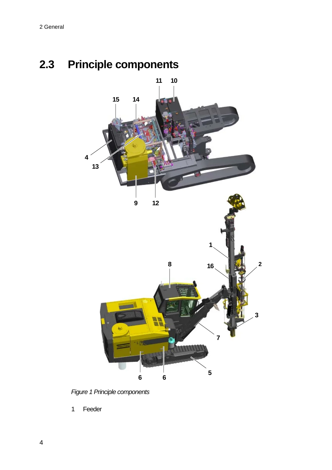
- General – foreword, application, principle components, general system description
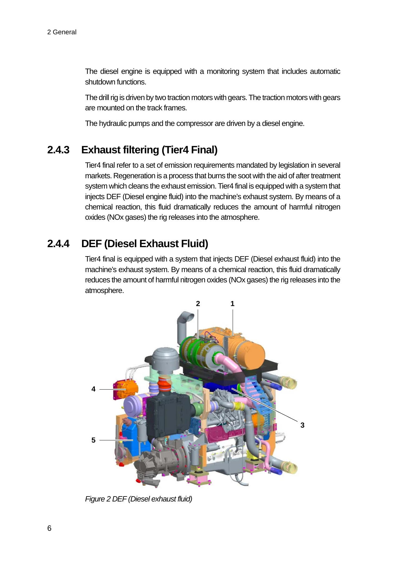
- Wagon frame with track frames, power pack, exhaust filtering (Tier4 Final), DEF (Diesel Exhaust Fluid)
- Boom system, dust collector, electrical system, hydraulic system, air system
- Technical data – specification, dimensions, transport dimensions, coverage area, feeder incline angles
- Daily checking – special safety inspection, check points, before starting, functionality test after starting, function test while drilling
- Controls – general layout, symbol identification, cab, pressure gauge panel, engine control panel
- Drill control lever, feed control lever, carousel and RHS control panels (T45SF and T45LF)
- RHS auto mode control system flow and operation of the RHS control lever in Auto Mode
- Positioning levers, oscillation and tramming control panel, control panel, electrical panel
- Regeneration control panel, hydraulic oil temperature, gradient meter, emergency hammer, fire extinguisher
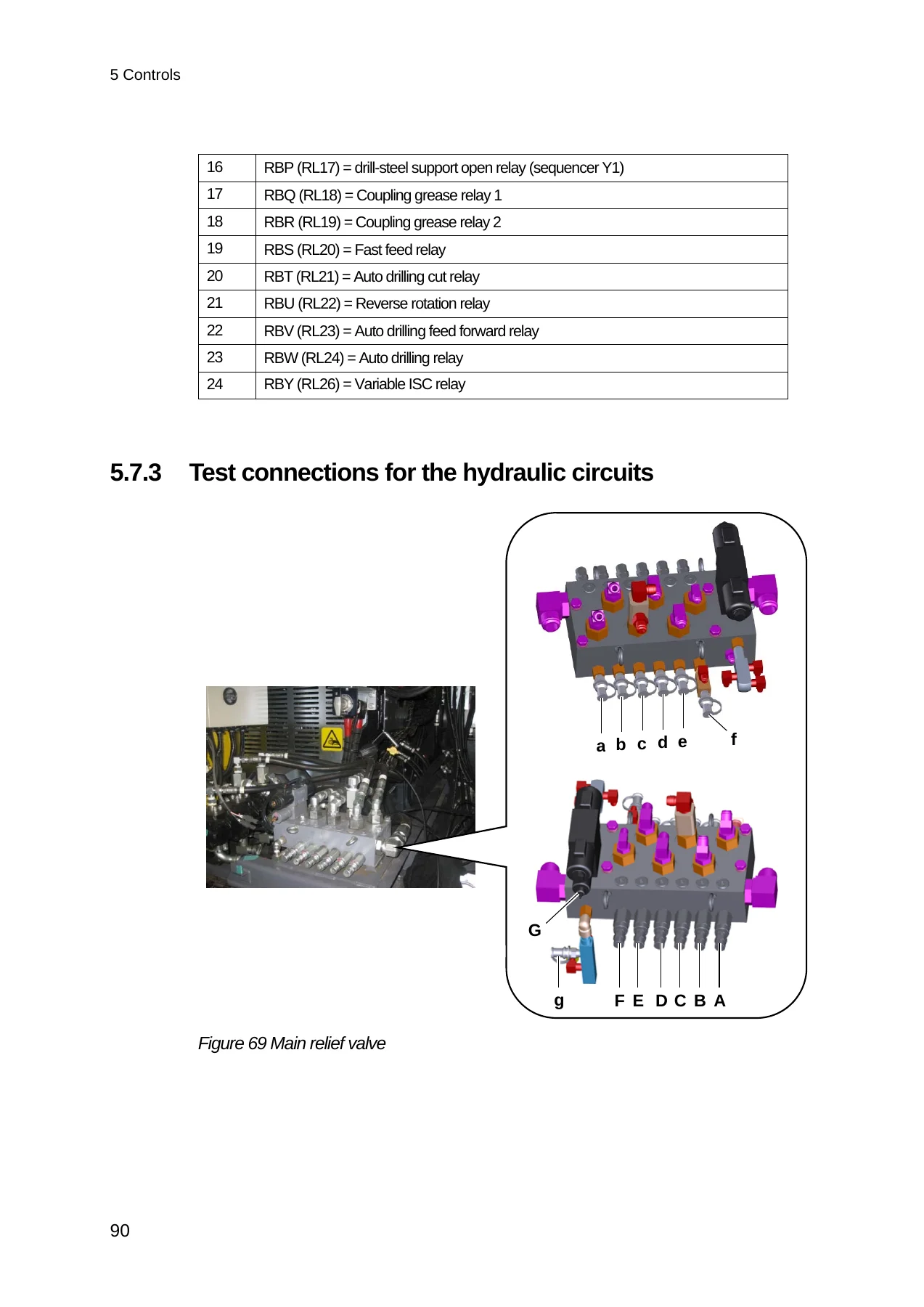
- Other controls – electric cabinet (A), electric cabinet (B), test connections for the hydraulic circuits
- Operating – starting the diesel engine, stopping the diesel engine, repositioning, checking after tramming, tramming general principles
- Before drilling – safety, loading the pipe carousel, setting up for drilling
- Drilling – start of drilling, checks during drilling, jointing drill pipes, retracting drill string
- Changing drill bit, action in case of drilling problems, water mist system operation
The eight chapters together build a complete operating picture rather than a collection of disconnected topics. The general chapter identifies the principle components and then works through each system in turn: the wagon frame and track frames, the power pack, the Tier4 Final exhaust filtering with DEF dosing, the boom system, the dust collector, the 24 V electrical system, the five-pump hydraulic system and the compressed air system. From there the PowerROC T45 instructions move into the cab and stay there, because that is where the job is actually done.
Controls, Rod Handling and the RHS Auto Modes
A full symbol identification chart removes the guesswork from unfamiliar decals before the operator touches anything. The manual then walks panel by panel through the pressure gauge panel with its engine monitor and warning codes, the engine control panel with the Power Eco speed selector and tram/drill switch, the drill and feed control levers with their trigger switches and button functions, the positioning levers, the oscillation and tramming control panel, the electrical panel, the air conditioner control panel and the regeneration control panel used with the Tier4 engine.
Separate sections are devoted to the carousel and RHS (rod handling system) panels for the PowerROC T45SF and the PowerROC T45LF, including the RHS mode selector, the RHS/dust collector/flushing air selector, rod lock gate, gripper arm hard clamp, soft clamp and open clamp positions, carousel rotation switch and the top button switch whose function changes between manual, auto and drill modes. The RHS auto mode control system flow is shown for both the adding mode and the removing mode, followed by step-by-step operation of the RHS control lever in Auto Mode for each variant. These are the sections that turn a complicated rod handling cycle into a repeatable sequence.
Daily Checking and Safety Before Each Shift
The daily checking chapter sets out the special overall visual safety inspection to be carried out before every shift, with a labelled check point illustration covering the feed cylinder, hose drum and cradle, cylinder brackets, feed holder, boom head, track frames, operator’s cab brackets, boom support, boom, rod handling system and drill-steel support. It lists what to look for: damage that could cause structural weakness or cracks, wear with severe consequences, and fractures in materials or welded joints, particularly after the rig has been subjected to abnormally high stresses. Fluid and lubricant level checks, water draining from the fuel pre-filter and compressor separator tank, and the emergency stop function test are all spelled out in table form. The safety instructions throughout the manual carry explicit warnings about movable parts, compressed air pressure, side hatches, working under the rig and the dangers of approaching the carousel or pipe gripper area.
Operating and Drilling Procedures
The operating chapter covers starting the Cummins diesel engine in the correct switch sequence, stopping it after high-power drilling or tramming, and repositioning the rig with the feeder laid down on its support. Tramming principles are explained with maximum permitted angles of inclination for forward, reverse and lateral travel, both with the feeder horizontal and with the feeder vertical and centred between the track frames, plus the rule that track oscillation stays open while tramming and locked when setting up to drill.
Before drilling, the manual describes loading the pipe carousel, setting up on the hole, and using the feed extension cylinder to apply down force. The drilling chapter then follows the complete cycle: collaring with reduced flushing air, switching to full flushing, engaging auto drilling, jointing drill pipes, retracting the drill string, and changing the drill bit. Troubleshooting guidance is included for hot coupling sleeves, difficulty loosening coupling sleeves, hole deflection, drilling through overburden, drilling with water in the hole, and operation of the optional water mist system.
Technical Data and Operating Limits
The technical data chapter gives the figures an operator needs to stay within the machine’s limits: weights for the T45SF and T45LF, engine power rating, temperature range, tramming speeds and tractive force, ground clearance, maximum hydraulic pressure, track oscillation, noise and vibration levels, tilt angles for drilling and tramming, hydraulic and electrical system data, air system output, fluid capacities, climate unit refrigerant, and the hydraulic rock drill RD22S impact power, pressure, impact rate, torque and weight. Transport dimensions, coverage area, vertical and horizontal reach, and feeder incline angles are all illustrated with dimensioned drawings.
Put the PowerROC T45 Operator Instructions to Work
This manual is what keeps a PowerROC T45SF or T45LF running to its intended procedure instead of to guesswork. It supports the daily inspection routine that catches cracked brackets and worn components before they fail, the correct start-up and shut-down sequence for the engine, accurate setting of percussion, feed and rotation pressures for the rock being drilled, and the full add-rod and remove-rod cycles in RHS auto mode. It gives the operator a defined response to hot coupling sleeves, stuck couplings, hole deflection and water in the hole, and it puts the tilt angles, capacities and pressure limits in front of them before a limit is exceeded.
Working from the correct Atlas Copco procedures and specifications matters on a rig of this size, where an incorrect flushing setting, an over-tightened coupling or an ignored warning lamp turns into downtime, damaged drilling tools or a safety incident. The 9852 3870 01 operator instructions put the manufacturer’s own sequences and values in the hands of whoever is on the rig.
IMAGES PREVIEW
Delivery is instant: the PDF is available for download immediately after checkout, with no shipping and no waiting. Print the pages you need for the cab or the workshop, or open the file on a laptop, tablet or phone at the drill site.


Reviews
There are no reviews yet.