
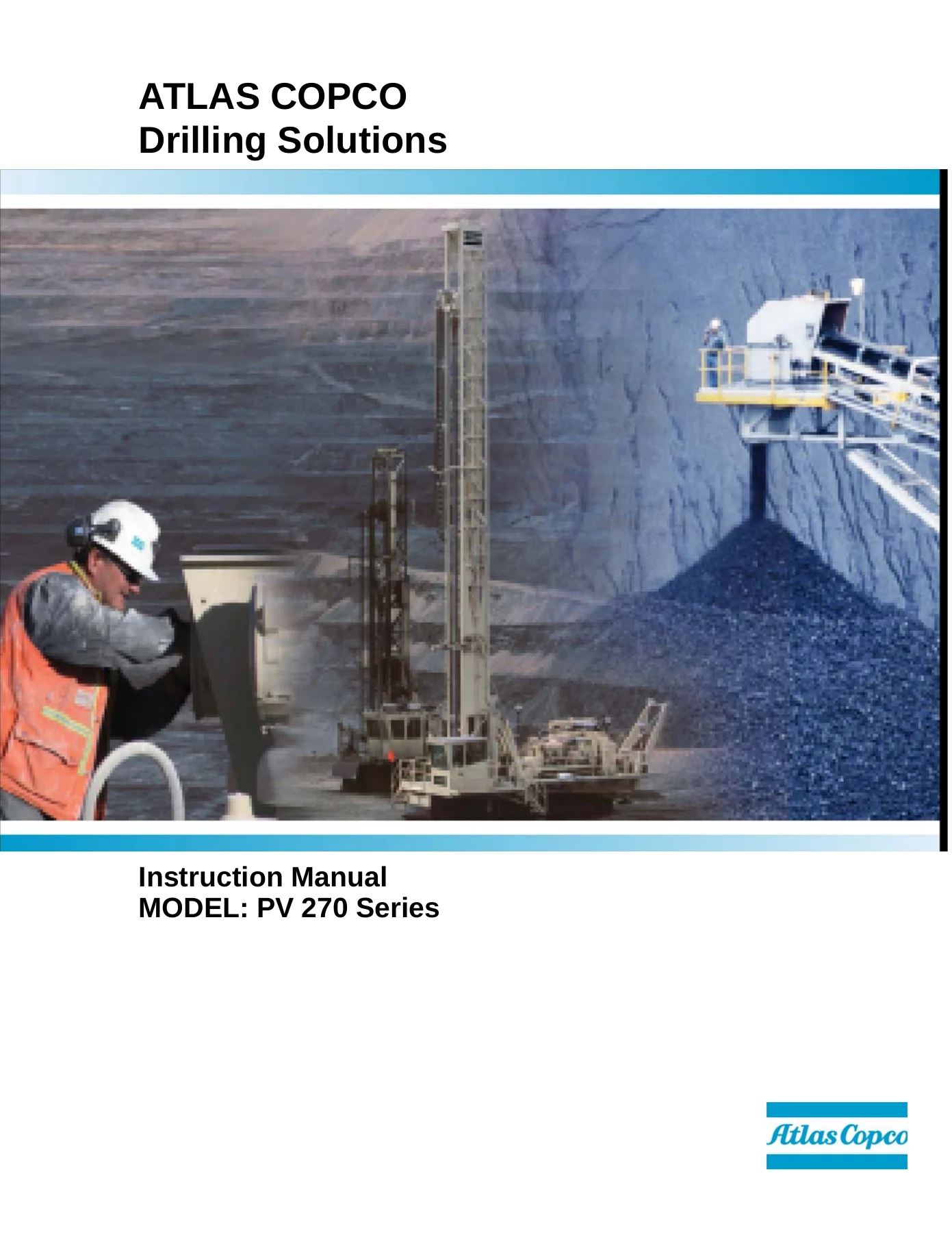
Atlas Copco PV-270 Series Blasthole Drill Instruction Manual – PV-271 & PV-275 Safety, Operation & Maintenance PDF
Original price was: $44.95.$26.95Current price is: $26.95.
Complete Atlas Copco PV-270 Series blasthole drill instruction manual covering the PV-271 Single-Pass and PV-275 Multi-Pass rigs. 802 pages of safety, specifications, controls, operating procedures, scheduled maintenance, hydraulic and electrical systems, compressor regulation and troubleshooting. Instant PDF download.
Description
Atlas Copco PV-270 Series Blasthole Drill Instruction Manual
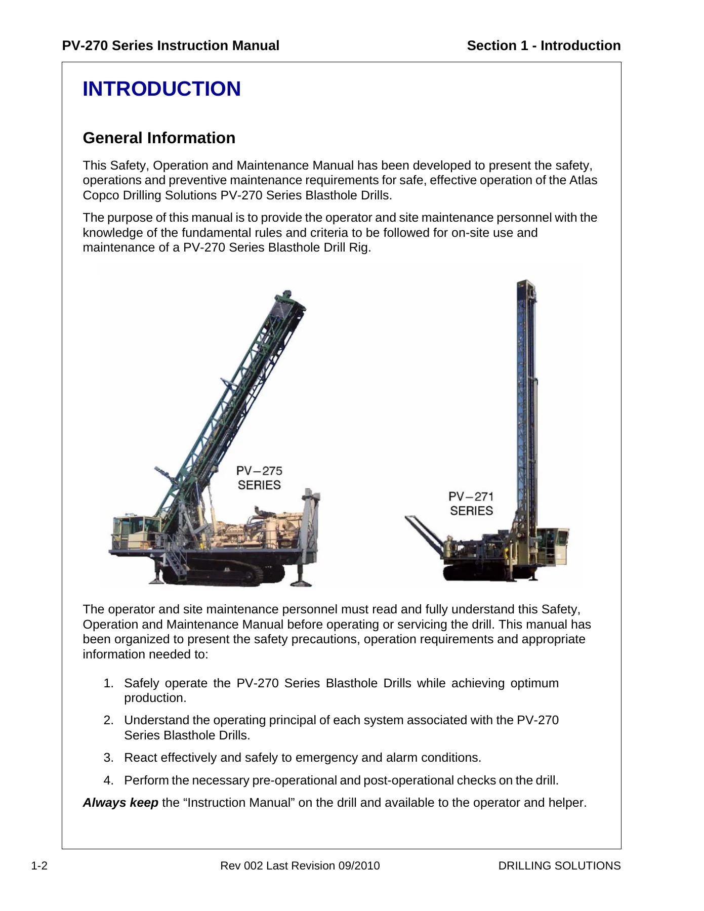
The Atlas Copco PV-270 Series Blasthole Drill Instruction Manual is the complete Safety, Operation and Maintenance reference for the PV-271 Single-Pass and PV-275 Multi-Pass track-mounted blasthole drills. Written for the operator, helper and site maintenance technician, this PV-270 Series instruction manual combines every procedure needed to run the rig safely, keep it productive, and service it correctly between shifts. It covers machine layout and identification, safety and health, full technical specifications, console controls, operating sequences, scheduled maintenance, hydraulic and electrical system descriptions, compressor regulation, and the troubleshooting trees used to diagnose faults in the field.
This is the same style of manual issued with the PV-270 Series blasthole drills from the factory, and it is built around real operating procedures rather than general theory. Every section speaks directly to the PV-271 and PV-275 — their derrick, carousel, rotary head, feed system, power pack, cooling package, air compressor, hydraulic reservoir, leveling jacks, dust control and operator cab. If you run, repair or buy support documentation for a Pit Viper PV-270 Series rig, this is the document the whole maintenance program is built on.
File Details
- Manual type: Safety, Operation and Maintenance Instruction Manual
- Brand: Atlas Copco Drilling Solutions
- Series: PV-270 Series Blasthole Drills
- Models covered: PV-271 (Single-Pass) and PV-275 (Multi-Pass)
- Language: English
- Format: PDF
- Page count: 802 pages
- Revision: Rev 002, Last Revision 09/2010
- Sections: 1 through 8 plus Engine Oil Addendum (Section 11)
Chapters Covered in the PV-270 Series Instruction Manual
- Section 1 – Introduction — General information, how the manual is organized, procedure when receiving the drill, drill identification, engine identification, instruction manual location, drill description of the PV-271 and PV-275, derrick, engine, main frame, drill tower, controls, tramming, steering, braking, operator cab and console, gradeability, serviceability.
- Section 2 – Safety — Safety and health statement, emergencies, important safety instructions, safety precautions and guidelines, drill applications, qualifying personnel, general guidelines, equipment safety rules, pre-start inspection, operation safety, maintenance safety, hydraulic maintenance safety, warnings of special dangers (overhead electric wires, ventilation, grade limitations), transportation safety, towing safety, safety decals and nameplates list and locations, hazardous substance precautions, symbol identification.
- Section 3 – Specifications — General description, drill applications, designated and non-designated applications, design features, environment rate factor ranges, operational limitations, standard equipment and specifications, main frame, leveling jacks, undercarriage and propel system, tower, carousel and drill pipe handling, drill pipe change, feed system, power pack, cooling package, air compressor, hydraulic system, pumps, motors, cylinders, dust control, operator’s cab, operator’s console, night lighting specifications, standard tools and manuals, dimensions and weights, optional equipment.
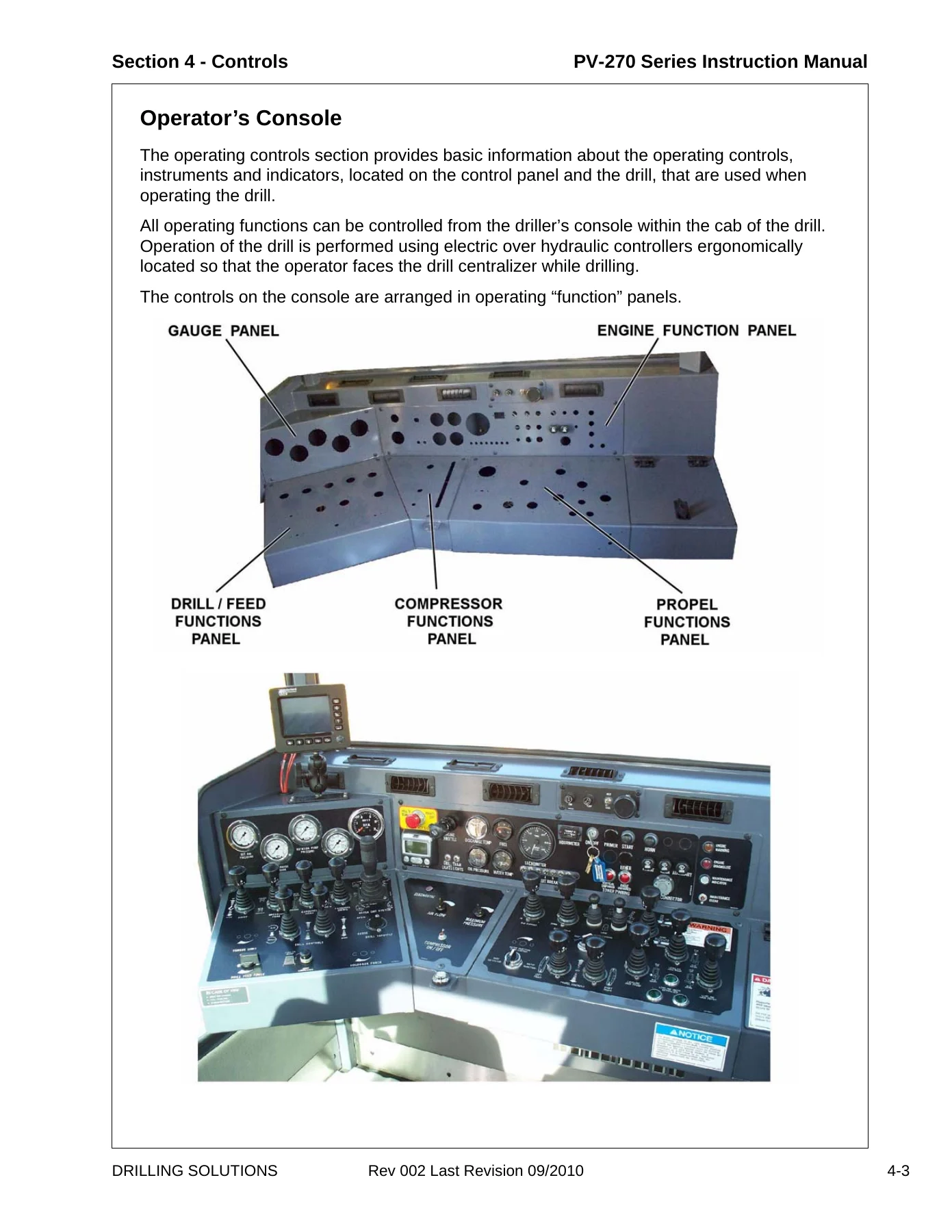
- Section 4 – Controls — General information, operator’s console layout, controllers for hoist, breakout fork, carousel index, carousel swing, breakout wrench, torque limit, rotation, drill feed, drill throttle, drill feed force control, joint lubricator, holdback force, gauges panel (bit air pressure, supercharge pressure, rotation pump pressure, pulldown pressure, holdback pressure), emergency stop, engine speed selector, discharge temperature, fuel level, PowerView diagnostic display, drill and tram lights, engine oil pressure, engine coolant temperature, tachometer, circuit breakers, hourmeter, key switch, engine fuel primer, engine starter, ether cold start option, tower unpinned warning lights, horn, wipers, data link socket, air pressure regulator, compressor volume control, compressor ON/OFF, compressor throttle, rod support, dust curtains, tower locking pins, tower raise/lower, water injection flow control, propel/drill mode selector, track propel controllers, leveling jack controllers and indicator lights, bubble level, heat/air conditioning, inclinometers, instruction manual storage, operator’s seat, non-cab controls and instruments, engine preheater timer, automatic cable tensioner controls.
- Section 5 – Operating — Operating safety, walk-around inspection, pre-start inspection (engine oil, coolant, fuel, fuel filter/water separator, compressor oil, receiver tank water drain, batteries, pump drive gearbox oil, hydraulic oil level), pre-operation controls inspection, engine operation (start, verify gauges, engine speed control, water temperature), stopping engine (high pressure, low pressure, EARS), emergency shutdown, starting and stopping hints, compressor operation (low pressure, high pressure, EARS), propel (tramming) operation, backup alarm check, hydrostatic brake check, drill setup, leveling the drill, tower raising and locking, angle locking, tower lowering, overpressure control system and test, carousel, drill rod handling, initial drill rod loading, field replacement, adding drill rod procedures, adding drill rod to drill string, removing drill rod from drill string, rotary drilling procedures, starter rod/stabilizer installation, tricone bit installation, bit removal, DHD drilling, DHD button bit installation, DHD drilling procedure, removing DHD from drill string, bit removal, general drilling hints, angle drilling, stopping, parking and shutdown, normal shutdown, emergency shutdown, daily precautions after work, mounting and dismounting, towing, special conditions of use (cold weather, hot weather, water and muddy, dusty, high altitude), preservation and storage.
- Section 6 – Maintenance — Maintenance safety and health, safety precautions, maintenance schedule (as required, 8-10 hours/daily, 50 hours, 100 hours, 150 hours, 250 hours, 500 hours, 1000 hours, 1500-2000 hours, 3000 hours, 6000 hours), refill capacities, lubricants and fuel (hydraulic oil, compressor fluids, rotary head oil, pump drive oil, final drive oil, hoist/winch lubricant, water injection pump lubricant, grease types), engine lubricating oil, engine coolant, fuel oil specifications, maintenance as required (air cleaners, indicators, connections and ducts, dust cups, pre-cleaner, rain guard, elements), clean the drill, loose bolted connections, feed cable and wire rope, cable tensioning procedure, replacement guideline, cable lubrication, feed cable replacement, wire rope clamps and installation, grease drum option, compressor air hoses and clamps, maintenance at 8-10 hours, overpressure control system test, air cleaners, engine oil level, engine belts and tensioners, belts adjustment and replacement, engine fuel/water separators, cooling system maintenance, radiator coolant level, clean radiator and oil coolers, fuel tank, receiver separator, compressor oil level, receiver separator element, hydraulic reservoir oil level, hydraulic oil filters, rotary head oil level, rotary head upper bearing, gearbox drive shaft, dust collector, clean the drill, maintenance at 50 hours, batteries, pump drive gearbox, undercarriage (final drive mounting bolts, oil leaks, oil level), tracks (track tension, track adjustment), auxiliary hoist, Cat water injection pump, maintenance at 100-150 hours, auxiliary hoist oil change, track planetary gearbox, maintenance at 250 hours, CAT engine oil and filters, CAT fuel filters, CAT coolant filter, SCA level, engine valve lash, Cummins engine oil and filters, Cummins fuel filters, Cummins coolant filter, Cummins SCA level, auxiliary hoist wire rope condition, maintenance at 500 hours, CAT primary fuel filter/water separator, batteries clamps and cables, fuel tank breather and primer pump, hydraulic tank breathers and fluid condition limits, change hydraulic oil, compressor oil strainer and filters, pump drive gearbox oil, auxiliary hoist oil level, cable/rope lubrication, automatic tensioners, Cat water injection pump, compressor air hose and clamps, compressor discharge hose and clamps, John Bean water injection pump, maintenance at 1000 hours, compressor oil change, hydraulic oil filters, rotary head oil change, pump drive gearbox oil change, auxiliary hoist oil change, water injection pumps, maintenance at 1500-2000 hours, track planetary gearbox oil change, air cleaners primary and safety elements, compressor discharge hose, compressor, compressor fire prevention, receiver separator element, engine belts and tensioners, maintenance at 3000 hours, CAT engine valve lash, maintenance at 6000 hours, engine coolant drain/flush/fill, torque specifications (standard torque values in ft/lbs and Nm).
- Section 7 – Systems & Troubleshooting — Troubleshooting information, general information, electrical controls, operator observed problems, pneumatics, mechanical hydraulic components, mechanical engine, electrical system information (Cummins engines, Cat engines), electrical system components (batteries, fusible links, starter motor, alternator, key switch, circuit breakers, push buttons), engine shutdown devices (compressor discharge temperature switch, engine water temperature switch, engine oil pressure switch, tachometer/magnetic pickup, relays, emergency engine shutdown), Cat electronic engine, Cat monitoring system, warning/derate/shutdown, Cat diagnostic and monitoring system, fault logging, diagnostic lamp, diagnostic flash codes, Cat engine protection, Cummins engine electronics, indicator light system, QSK19 diagnostic fault codes, diagnostic switch, incremental switch, finding and reading fault codes, Murphy Link PowerView system (description, features, mechanical and electrical installation, operation, main menu navigation, selecting language, stored fault codes, engine configuration data, faults and warnings, auxiliary gauge fault, active fault codes, shutdown codes, backlight and contrast adjustment, select units, setup 1-up display, setup 4-up display, utilities, MODBUS setup, J1939 parameters, glossary), electric ladder, electrical symbols, troubleshooting (operator observed problems), low pressure compressor (pneumatic system information, compressor fire prevention, lubrication system components, oil flow, separation system, regulation system, inlet butterfly valve, discharge check valve, blowdown valve, receiver tank, minimum pressure valve, safety relief valve, automatic inlet unloading, anti-rumble system, compressor related problems), low pressure compressor with EAR’S (pneumatic system information, electronic air regulation system, components, flow sensor, proportional butterfly valve and actuator, pressure sensor, proportional vent valve and actuator, electronic controller, flow control knob, maximum pressure control knob, compressor ON/OFF switch, diagnostic light, hardware interface board, interconnect system, oil pressure switch, shaft speed sensor, engagement sensor, operation, startup, shutdown, flow regulation, maximum pressure regulation, emergency venting, compressor turning, gear selection error detection, temperature regulation, flow chart, EAR-EFR diagnostics, standard test conditions, error code meaning and diagnostic information, blown fuse check list, actuator diagnostics table, actuator test, potentiometer testing, tables, schematics), high pressure compressor (pneumatic system information, compressor fire prevention, overview, lubrication system components, receiver-separator tank, oil pump, strainer, oil cooler, compressor oil, mixing valve, relief valve/check valve, oil filter, discharge check valve, lubricating system operation, separation system, regulation system – high pressure, inlet butterfly valve, UL88 unloader valve, ON-OFF valve, 50 psi relief valve/orifice, 100 psi check valve, volume control valve, operation, pressure regulator, anti-rumble valve, blowdown valve, shutoff valve, quick exhaust valve, minimum pressure valve, safety relief valves, drill air throttle valve, service connection, pressure gauge, regulation system schematic, shutdown system, operation, starting, adjusting pressure, drilling, shutting down, air pressure regulator, theory of operation, increasing pressure, decreasing pressure, compressor related problems), high pressure compressor with EAR’S (pneumatic system information, electronic air regulation system, components, operation, flow chart, EAR-EFR diagnostics, standard test conditions, error code meaning, blown fuse check list, actuator diagnostics, potentiometer testing, tables, schematics), hydraulic system introduction, hydraulic symbols (fluid power symbols, line symbols, reservoir/tank, fluid container, accumulator, restrictor, cylinders, activating device, miscellaneous, pump and motor, pump symbols, motor symbols, instrument symbols, valves, three position 4-way valve, valve centers, series parallel valve, manual on-off, pressure relief, sequence, pressure reducing, check, pilot operated lock check, bypass, overcenter, review), propel system (propel circuit, components, main hydraulic pumps, propel motors, propel motor brake, diverter valve assembly, propel/drill mode selector, drill/propel control valve, loop filling/replenishment, loop flushing circuit, circuit operation, oil path selection), feed & rotation system (feed system, mechanical system, hydraulic system, feed, feed pump, feed cylinders, holding valve, overcenter valve, pressure control valve, two-way valve, diverter valve assembly, drill/propel control valve, remote compensator control, jack two-way valves, over pressure control, over pressure system test, feed circuit operation, oil path selection, cylinder extend and retract, loop filling/replenishment, rotation system, main pump, rotation motors, rotation motor displacement adjustment, rotation motor control valve, rotation circuit operation, rotation, motor displacement control, drill/propel control valve, oil path selection, loop filling/replenishment), auxiliary function circuit (auxiliary functions, components, double pump, P1 pump circuit, P2 pump circuit, motors, cylinders, relief valves, check valves, two way valve, holding valves, pilot check valves, sequence valves, seven spool valve, first through seventh valve sections, eleven spool valve, first through eleventh valve sections, P2 pump circuit, circuit operation, cooling circuit/cable tensioners, cooling control valve, fan motor, circuit operation, manifold system, return drain manifold, supercharge suction manifold, filter assembly, hydraulic reservoir, circuit operation, service notes, pressure test ports, hydraulic fluid, fluid sampling, hydraulic reservoir, hydraulic connections, diverter manifolds, drill/propel control valve, manifold assemblies, feed system control valve, 7-spool valve, 11-spool valve, cooling control valve), electro hydraulic system (overview, general concepts and terminology, current control, pulse width modulation, threshold, maximum out, controllers, dual range, single coil, dual coil, Denison 500 stroker, Denison 500 stroker adjustment, valves, Apitech pulsars, 7-spool valve, 10-spool valve, holding valve, controllers, pulldown controller, water injection rotary activated controller, limit switches, relays, typical coil resistance, adjustments, Apitech coils, Fema coils, proportional remote control output, checking relay, checking limit switch, checking diode), EHC operation (jack controllers, hoist controller, tower raising controller, rod indexer controller, breakout fork wrench controller, carousel swing controller, water injection controller, dust collector, tower pinning, tower angle leg pinning, drill propel valve, drill feed circuit, rotation control, LP drill feed and rotation controller, feed controller, drill feed force/no bump rod changer, holdback control, rotation control, torque limit control), EHC adjustments (feed and rotation controllers, propel controller adjustment, auxiliary function controllers, pulldown force rotary controller, holdback rotary controller), troubleshooting (dust collector), troubleshooting (centromatic lube), engine heater (introduction, technical specifications, principal of operation, fuel pump, fuel regulator, air compressor, ignition coil, coolant pump, Proheat control module, nozzle, blower, inspection port, heat exchanger, ignition electrode, coolant temperature sensor, overheat breaker sensor, flame sensor, on/off switch, seven day timer, normal operating sequence, function and component diagnostics, troubleshooting and repair, component diagnostics, operational problems, maintenance, timer), Dixon Boss clamp selection and installation (safety information, STAMPED, general preparation instructions, Dixon diameter tape procedures, Boss clamps, Boss clamp selection, criteria for sufficient fit, installation of Boss 2 bolt clamp, 4 bolt clamp, 6 bolt clamp, testing, hydrostatic testing, electrical continuity testing), HNBR hose/Victaulic coupling installation (coupling installation, preparatory steps, coupling installation, impact wrench usage guidelines, installation inspection), water injection (Cat water injection, installation and startup, specifications, lubrication, oilers, inlet conditions, nozzles, discharge plumbing, pumped fluids, inlet condition check list, diagnosis & maintenance, servicing the valve assemblies, servicing the valve pumping section, servicing sleeves and seals, servicing the crankcase section, torque chart, manifold torque sequence, pulse pump injection head, troubleshooting), DHD lubricator (timer, lube injection pump, flow switch, diagnostics, oil, pressurized air, output, output detection, flow switch adjustment, DHD lubricator diagnostic summary), feed cable tension adjustment.
- Section 8 – Glossary — Glossary of terms and manual revisions.
- Section 11 – Engine Oil Addendum — Engine oil update, Caterpillar engine, Cummins engine.
In practical terms this PV-270 Series instruction manual gives the technician an end-to-end reference for the PV-271 and PV-275 rigs: how the machine is laid out and identified, how each system is designed and operates, what the correct operating sequences are, what maintenance is required at each interval, what the key specifications and capacities are, and how to diagnose faults through the electrical, pneumatic, hydraulic and compressor systems. Because the manual moves from safety theory through operating procedure into scheduled maintenance and then into system-level troubleshooting, it is used both as a daily operator reference and as a workshop repair guide.
Engines Covered
Engine data and operating requirements are included for the diesel and electric power options offered on the PV-270 Series platform, including the Cummins QSK19C and the Caterpillar C27 and C32 engines, plus the WEG electric motor options. Engine-specific maintenance (oil and filter intervals, belt tensioning, fuel filters, coolant filters, SCA levels, valve lash) and engine electronics/diagnostics (Cat ECM and Cummins QSK19 fault codes) are covered inside the manual alongside the drill systems.
Who This Atlas Copco PV-270 Series Manual Is For
Operators running PV-271 and PV-275 blasthole drills who need the correct start-up, shutdown, tramming, drilling, rod handling and angle drilling procedures. Maintenance technicians and mechanics responsible for daily, 50-hour, 250-hour, 500-hour, 1000-hour and major interval services. Site supervisors who need the safety rules, PPE requirements and shutdown devices documented in one place. And owners or fleet managers who need the reference that keeps a PV-270 Series rig productive instead of parked.
What This Manual Helps You Do
- Run the PV-271 Single-Pass and PV-275 Multi-Pass drills through their full operating cycle — pre-start inspection, engine and compressor start-up, leveling, tower raising and locking, carousel operation, drill rod handling, rotary and DHD drilling, angle drilling, and shutdown.
- Perform scheduled maintenance correctly — every interval from the 8–10 hour daily checks up through 50, 250, 500, 1000, 1500–2000, 3000 and 6000 hour service items.
- Find the correct lubricant, fluid and refill capacity for the hydraulic reservoir, compressor receiver tank, rotary head, pump drive gearbox, final drives, water injection pumps and hoist.
- Understand how the hydraulic propel, feed, rotation and auxiliary circuits operate, how the diverter and drill/propel valves shift flow between drill and propel modes, and where to check pressures at each test port.
- Read and interpret the electrical system, circuit breakers, engine ECM diagnostics, Cat diagnostic flash codes and Cummins QSK19 fault codes.
- Set up and adjust the low-pressure compressor, high-pressure compressor, and Electronic Air Regulation System (EAR’S).
- Service the compressor oil system, oil cooler, receiver separator element, and the fire-prevention static grounding staples.
- Troubleshoot the dust collector, Centromatic lube system, DHD lubricator, engine heater, water injection pumps, feed cable tension and final drive planetary gearboxes.
- Select and install Dixon Boss clamps, Victaulic couplings and HNBR hose assemblies to specification.
Why the PV-270 Series Instruction Manual Matters
Blasthole drills of this class are unforgiving when something is set up wrong. Compressor shutdown at high pressure can push oil into the air cleaners. Feed cylinders without purged air can drop the derrick. A cooler that has been bypassed or a receiver separator installed with drain holes at the wrong end will lead to oil carryover or a fire. The Atlas Copco PV-270 Series instruction manual documents the correct procedure for every one of those situations, along with the safety distances, PPE, lockout/tagout, and shutdown-device behavior that protect the crew around a running rig.
Having this manual on hand also means maintenance is done to the manufacturer’s actual intervals and capacities instead of guesswork, which directly extends engine, compressor, hydraulic and undercarriage life — and keeps the rig on the bench drilling holes instead of waiting on parts.
IMAGES PREVIEW
Instant PDF Delivery
This Atlas Copco PV-270 Series Blasthole Drill Instruction Manual is delivered as a PDF download immediately after purchase — no shipping, no waiting, no physical book to carry. Open it on a laptop in the shop, a tablet in the cab, or a phone on the bench. Search the 802 pages, print the sections you need for the job at hand, and keep a permanent copy on file for the life of the rig. Whether you are running a PV-271 Single-Pass or a PV-275 Multi-Pass, this is the reference that covers the machine end to end.

Reviews
There are no reviews yet.