
ATR 72-212A PW120 B1 & B2 Part-66 Phase 1 Training Manual – PDF
Original price was: $39.95.$23.95Current price is: $23.95.
622-page DCAM Part-66 Phase 1 course notes for the ATR 72-212A on Pratt & Whitney Canada PW 120 engines, covering ATA 00 through ATA 31 including publications, time limits, servicing, standard practice, indicating and recording, electrical power and communications.
Description
ATR 72-212A (PWC PW 120) B1 + B2 Phase 1 Course Notes
This ATR 72-212A PW120 B1 & B2 Part-66 Phase 1 Training Manual is a 622-page technical training document written for the DCAM Part-66 B1 and B2 licence syllabus on the ATR 72-212A powered by Pratt & Whitney Canada PW 120 series engines. It is issued as Book 1 of 1 of the Phase 1 course, Issue 1 Rev 0, dated July 2016, and it works through the airframe and systems modules that make up the opening phase of the type training syllabus: aircraft introduction, technical publications, time and limits, weighing and levelling, parking and mooring, servicing, standard practice, indicating and recording, electrical power and communications.
Because the ATR 72 and the ATR 42 share a common design lineage, the course material also carries the ATR 42 general description, dimensions, weight and loading figures, composite material map and engine data. A technician studying either airframe will therefore find the shared systems content directly applicable, and the comparison between the two types is built into the presentation rather than bolted on.
The document is laid out as a teaching text rather than a look-up manual. Each system is introduced from the ground up, diagrams are annotated with labelled callouts, and control panels, indicators and their colour logic are explained before the operating sequences are described. That structure makes it a useful study companion for licence candidates and a practical orientation reference for engineers moving onto the type for the first time.
File Details
- Manual type: Part-66 B1 + B2 type training course notes, Phase 1
- Aircraft: ATR 72-212A (PWC PW 120), with ATR 42 reference data
- Engines covered: Pratt & Whitney Canada PW 127F (ATR 72) and PW 127E (ATR 42)
- Language: English
- Page count: 622
- File format: PDF
- Issue / revision: Issue 1 Rev 0
- Date: July 2016
- Volume: Book 1 of 1
Chapters Covered
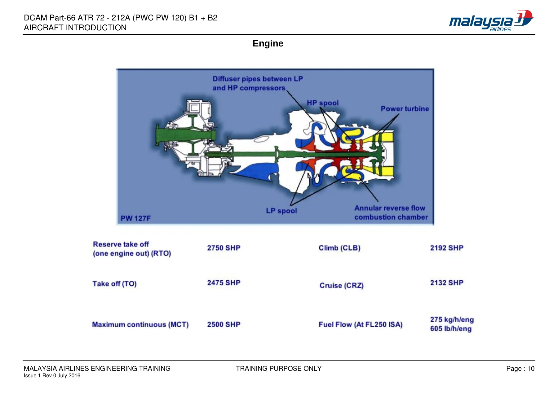
- ATA 00 Aircraft Introduction – ATR 72 and ATR 42 overview, production chart, main dimensions, weight and loading, cabin layout, cabin cross section, cockpit, composite materials, engine, performance, hotel mode, catering, indicator colour philosophy
- ATA 00 Publications – MPD, AMM, TSM, IPC, WDM (ASM / AWM / AWL), CLM, SRM, NDTM, TEM, CMM, SRKM, CPCICF, VD, VWM, VPSA, SB / SL, AC, FCOM, AFM, MMEL, CL, WBM, CCC, plus worked examples of using technical publications
- ATA 05 Time and Limits – inspection definitions, standard inspection intervals, structural inspection intervals, Maintenance Planning Document, maintenance precautions, CDCCL, engine and propeller maintenance, propeller interval escalation, component maintenance
- ATA 08 Weighing and Levelling – weighing methods, aircraft preparation, weighing on jacks, weighing on wheels, weighing on jacks and wheels
- ATA 10 Parking and Mooring – parking installation and removal, ground mooring, mooring limitations
- ATA 12 Servicing – external dimensions, ground clearance, exhaust temperature contours, engine danger areas, no step areas, jetway servicing, exterior inspection, ground service connections, air conditioning and electrical ground connections, refuelling panel and gravity refuelling, manual fuel quantity reading, hydraulic reservoir filling, potable water and toilet service, service interphone jack, landing gear safety pins, jacking for wheel removal, free fall assister nitrogen charging, towing, tyre pressure and wear, braking reservoir fluid level, tail bumper, tail prop, oil tank level, air data system draining, aircraft jacking, fuel tank and fuselage water drain
- ATA 20 Standard Practice – AMM standard practices covering line installation, cable checking, bonding, sealing, protective treatment and paint, repairs, swaging and fixing processes; AWM electrical equipment practices
- ATA 31 Indicating and Recording – general description, cockpit location, MFC description and operation, MFC maintenance panel, Multi Purpose Computer and MPS, MCDU, PCMCIA card, CCAS, CAP, master warning and caution, take-off config test, emergency audio cancel, LH maintenance panel, recording system, SSFDR, FDAU, accelerometer, indicators and recording panels, AIDS report transfer
- ATA 24 Electrical Power – general description, DC generation, batteries, TRU, external power, contactors, feeder overheat sensors, indicating, AC generation and inverters, ACW generation, GCU, BPCU, current transformers, controls and indicators, operational tests
- ATA 23 Communications – VHF, HF, passenger address, audio integrating with RCAU and ACP, cockpit voice recording, ELT, static dischargers, antennas, indicators and recording panels, VHF control unit maintenance operations
What makes this Phase 1 volume unusually practical is the way it links documentation to hardware. The publications chapter does not simply list the manuals an ATR operator holds; it walks through a fault from the Trouble Shooting Manual into the job instruction card, out to the Illustrated Parts Catalog, and back again. That single worked sequence teaches a reader how the ATR technical library interlocks, which is often the hardest part of type training to pick up from a stack of separate books.
Aircraft Introduction and Dimensions
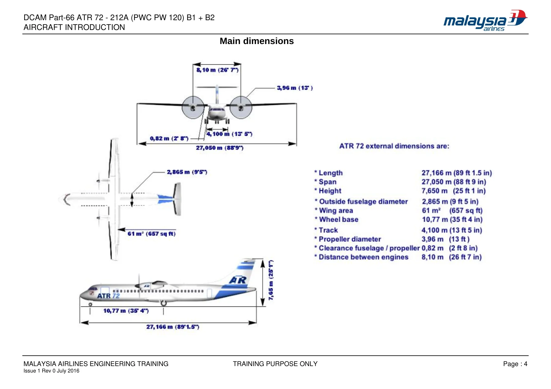
The opening module sets out the ATR 72 as a twin turboprop designed for 64 to 74 passengers, built in cooperation by EADS in France and ALENIA in Italy, with fuselage and tail produced in Naples, wings assembled at St Nazaire, and final assembly and flight test at Toulouse. Full external dimensions, cabin cross section figures and cabin height and width values are given, together with maximum take-off, landing, zero fuel and operational empty weights, payload and maximum fuel load. The same treatment is repeated for the ATR 42 so the two types can be compared directly.
Time Limits and Maintenance Intervals
The Time and Limits module defines the inspection families used across the ATR programme: line checks, A checks, C checks and the structural inspection tiers of General Visual, Detailed Visual and Special Detailed Inspection. Standard intervals are stated in flight hours and calendar days, and the structural inspection intervals are separated into fatigue, environmental and accidental damage categories with their thresholds and repeat intervals. Engine and propeller maintenance strategies, including hard time and on-condition approaches and propeller major inspection interval escalation, are covered alongside component time between overhaul figures for batteries, generators, propeller brake and landing gear.
Servicing, Parking and Mooring
The servicing chapter is the most illustration-heavy part of the document. Ground service connection points are mapped on a plan view of the aircraft, then each one is opened up in turn: air conditioning ground connection, AC and DC electrical ground connections, the refuelling electrical control panel with its automatic and manual override functions, overwing gravity refuelling ports, manual magnetic fuel quantity indicators and their dipstick readings, hydraulic reservoir filling, potable water and toilet servicing, landing gear safety pin stowage, jacking for wheel removal, free fall assister nitrogen charging, towing limits, tyre pressures and wear limits, and brake reservoir level checks. Parking and mooring procedures follow, with wind speed limitations that move the aircraft from normal mooring through rudder locking to hangar shelter.
Indicating, Recording and Electrical Power
The largest single systems block is the indicating and recording module. It explains the Centralised Crew Alerting System architecture built around the Multi-Function Computers, the four alert levels from warning through caution and advisory to information, the Crew Alerting Panel layout, master warning and caution logic, take-off configuration testing and the emergency audio cancel function. It then covers the recording chain in detail: the Flight Data Acquisition Unit, the Multi Purpose Computer and its AFDAU and DMU parts, the solid state flight data recorder and its underwater locating beacon, the accelerometer, the MCDU interface and the PCMCIA card used to carry data to the ground station. A separate module on the indication system covers the electrical clocks and cockpit panel architecture.
The electrical power module follows the same teaching approach, working through DC generation with the starter generators and their control units, the main and emergency batteries and their charge and transfer contactors, the transformer rectifier unit, external power connection, bus tie contactors, load shedding, the service and ground handling buses, AC constant frequency generation through the static inverters, and AC wild frequency generation from the engine driven ACW generators. Normal, abnormal and hotel mode operating sequences are described step by step, and the chapter closes with the controls and indicators found on the main electrical power panel and the maintenance panel tests for the GCU and BPCU.
Communications
The communications module covers the VHF and HF radio systems, the passenger address system with its cabin loudspeakers and attendant handsets, the audio integrating system built around the Remote Control Audio Unit and its Audio Control Panels, and the cockpit voice recording system including the solid state recorder, its control unit and erase and test functions. The emergency locator transmitter and the static discharger installation complete the section, along with annotated walk-throughs of the VHF and audio control panels and their indicator logic.
Putting the ATR 72-212A Phase 1 Manual to Work
With this ATR 72-212A PW120 B1 and B2 Part-66 Phase 1 training manual on hand, a licence candidate or line engineer can work through the aircraft from its general layout and documentation structure down to individual servicing points, electrical bus architecture and cockpit alert logic. It supports study for the Phase 1 type modules, preparation for practical assessments on servicing and ground handling tasks, and day-to-day orientation when a procedure needs to be understood in context rather than simply followed. The annotated panel diagrams and system block schematics are what make that possible.
Working from the correct references matters on a type where bus tie logic, alert level classification and servicing connection points all have consequences if they are misread. This volume gives the underlying reasoning behind each procedure so the task in front of you makes sense.
IMAGES PREVIEW
Delivery is instant. The PDF is available for download immediately after payment, with no shipping and no waiting. It opens on a laptop, tablet or phone, and any page or diagram can be printed for use at the aircraft or in the classroom. It should be read alongside the current approved maintenance documentation for the aircraft, since this is training material prepared for course purposes.
Reviews
There are no reviews yet.