
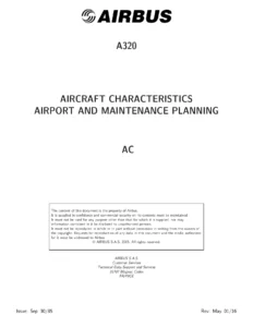
Airbus A319 Aircraft Characteristics Airport and Maintenance Planning Manual – A319-100 & A319neo (May 2017)
Original price was: $39.95.$23.95Current price is: $23.95.
Airbus A319 Aircraft Characteristics – Airport and Maintenance Planning manual, Revision 16 dated May 01/17. Covers A319-100 and A319neo with CFM56, IAE V2500, CFM LEAP-1A and PW 1100G engine data, ground clearances, jacking, pavement data and ACN/PCN tables.
Description
Airbus A319 Aircraft Characteristics Airport and Maintenance Planning Manual
This is the Airbus A319 Aircraft Characteristics – Airport and Maintenance Planning (AC) document, Revision No. 16, dated May 01/17. It serves as the single planning source that gives airport operators, airlines and Maintenance/Repair Organizations (MRO) the data they need for airport and maintenance facility planning on the A319-100 and A319neo.
The document is not customized and covers the A319-100 series equipped with wing-tip fences or sharklets, plus preliminary A319neo data. Everything inside is organized so a planner or engineer can find dimensions, ground clearances, jacking loads, servicing connections, engine efflux contours, turning paths and pavement classifications without hunting through separate publications.
File Details
- Manual type: Aircraft Characteristics – Airport and Maintenance Planning (AC)
- Brand: Airbus
- Models covered: A319-100, A319neo, A319 CJ
- Revision: Revision No. 16
- Revision date: May 01/17
- Language: English
- File format: PDF
- Page count: 348 pages
Chapters Covered
- Chapter 1 – Scope: Introduction, Glossary and design weight terminology
- Chapter 2 – Aircraft Description: General Aircraft Characteristics Data, General Aircraft Dimensions, Ground Clearances, Interior Arrangements – Plan View, Interior Arrangements – Cross Section, Cargo Compartments, Door Clearances and Location, Escape Slides, Landing Gear, Exterior Lighting, Antennas and Probes Location, Power Plant, Leveling Symmetry and Alignment, Jacking for Maintenance
- Chapter 3 – Aircraft Performance: General Information, Payload/Range ISA Conditions, Take-Off Weight Limitation ISA Conditions, Take-Off Weight Limitation ISA +15 degrees C Conditions, Landing Field Length ISA Conditions, Final Approach Speed
- Chapter 4 – Ground Maneuvering: Turning Radii, Minimum Turning Radii, Visibility from Cockpit in Static Position, Runway and Taxiway Turn Paths, Runway Holding Bay (Apron), Minimum Line-Up Distance Corrections, Aircraft Mooring
- Chapter 5 – Terminal Servicing: Aircraft Servicing Arrangements, Typical Ramp Layouts (Open Apron, Gate), Full Servicing and Outstation Turn Round Time Charts, Ground Service Connections, Grounding (Earthing) Points, Hydraulic System, Electrical System, Oxygen System, Fuel System, Pneumatic System, Oil System, Potable Water System, Waste Water System, Engine Starting Pneumatic Requirements, Ground Pneumatic Power Requirements, Preconditioned Airflow Requirements, Ground Towing Requirements, De-Icing and External Cleaning
- Chapter 6 – Operating Conditions: Engine Exhaust Velocities and Temperatures, Engine Exhaust Velocity and Temperature Contours (Ground Idle, Breakaway, Takeoff Power), Danger Areas of Engines, APU
- Chapter 7 – Pavement Data: Landing Gear Footprint, Maximum Pavement Loads, Landing Gear Loading on Pavement, Flexible Pavement Requirements (US Army Corps of Engineers Design Method), Rigid Pavement Requirements (Portland Cement Association Design Method), ACN/PCN Reporting System
- Chapter 8 – Scaled Drawings
- Chapter 10 – Aircraft Rescue and Fire Fighting: Hazardous materials and components, battery location and access, wheel/brake overheat, composite materials, emergency evacuation devices, doors and hatches, control panels, structural break-in points
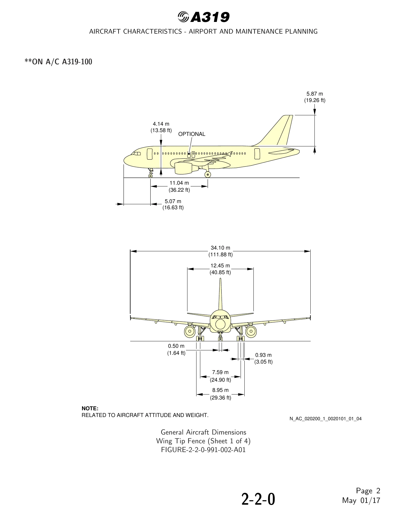
Read as a whole, this Airbus A319 Aircraft Characteristics Airport and Maintenance Planning manual gives a technician or facility planner one continuous data set that runs from the aircraft’s overall three-view dimensions and door sill heights right through to the pavement thickness the aircraft demands and the ACN it reports. Weight variant tables (WV000 to WV013 for the A319-100 and WV050 to WV055 for the A319neo) supply maximum ramp, take-off, landing and zero fuel weights, while the ground clearance charts break out door sill heights and wing, fuselage and tailplane clearances under forward CG, aft CG, light maintenance configuration and jacked conditions. Jacking data covers the forward fuselage and wing jacking points with maximum load eligible values, safety stay locations and the loads at each jacking point worked through a graphical example. The servicing chapter maps every ground connection – hydraulic green, blue and yellow system panels, electrical external power receptacles, oxygen, refuel/defuel, pneumatic, oil, potable water and waste water – with distance aft of nose, offset from centreline and mean height from ground so ramp equipment can be positioned correctly.
Engine Coverage Inside This A319 Manual
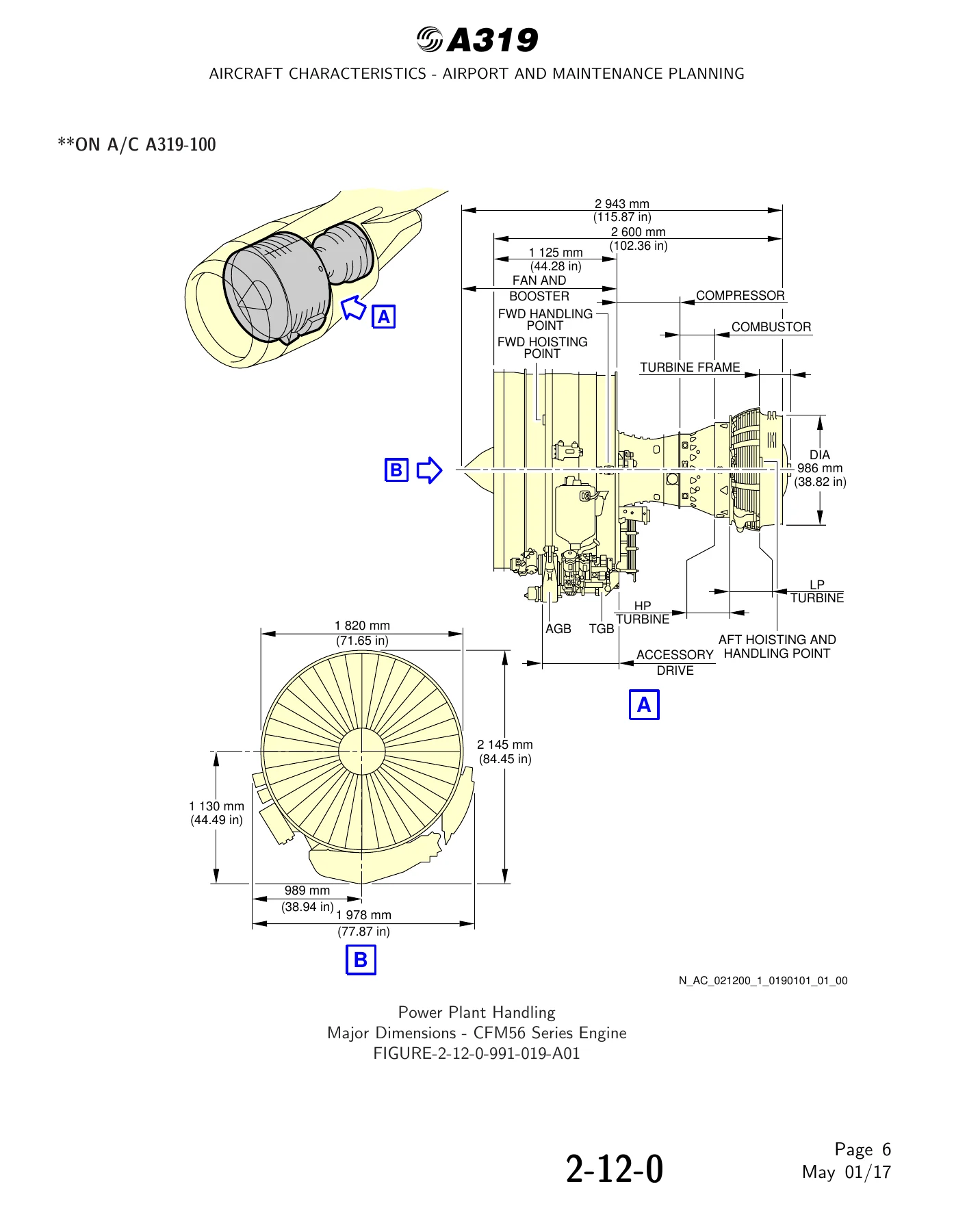
Engine-specific content is separated throughout, so the same chapter can be used whether the aircraft is fitted with a CFM56 series engine, an IAE V2500 series engine, a CFM LEAP-1A or a PW 1100G on the neo. Power plant handling sections give major dimensions, fan cowl opening data and thrust reverser half geometry for each engine family, including ground clearance references added in this revision. Chapter 6 follows the same pattern with exhaust velocity and temperature contours drawn separately for CFM56, IAE V2500, CFM LEAP-1A and PW 1100G at ground idle, breakaway power and takeoff power, and danger areas of the engines plotted for both ground idle and takeoff conditions.
Ground Handling, Turning and Pavement Planning Data
The ground maneuvering chapter works through the A319’s turning behaviour in detail: turning radii without slip angle, minimum turning radii at maximum steering angle with effective steering angle values, cockpit visibility angles in the static position, and complete turn path drawings for 135 degree and 90 degree runway-to-taxiway and taxiway-to-taxiway turns using both the cockpit over centreline method and the judgemental oversteering method. A 180 degree turn on a runway is covered using the edge of runway method and the centre of runway method, with nose gear, main gear and wingtip paths marked. Minimum line-up distance corrections are tabulated for runway entry, runway turn pad and runway width manoeuvres.
For airport pavement engineering, Chapter 7 supplies the landing gear footprint with main gear and nose gear tire sizes and pressures per weight variant, maximum vertical nose gear and main gear ground loads plus horizontal braking loads, and flexible and rigid pavement requirement curves with worked examples. The ACN table lists aircraft classification numbers against all-up mass for each weight variant across rigid subgrades of 150, 80, 40 and 20 MN/m3 and flexible subgrades of CBR 15, 10, 6 and 3, so a pavement can be matched to the aircraft directly.
Jacking, Towing and Maintenance Planning
Maintenance planners get jacking point locations, jack adapter dimensions, safety stay positioning between FR73 and FR74, jack design criteria, shoring cradle locations, and landing gear jacking data including main gear jacking with a cantilever jack, nose gear jacking point location, and the maximum load capacity to lift each jacking point. Ground towing requirements give drawbar pull and tow tractor mass determination, towbar design guidelines with traction and torsion shear pin calibration values, and the note on total traction wheel load.
What This Airbus A319 Airport and Maintenance Planning Manual Enables
With this Airbus A319 Aircraft Characteristics Airport and Maintenance Planning manual on hand, an airport planner can size taxiway fillets, apron stands, holding bays and pavement thickness against real A319 geometry and loads rather than estimates. A maintenance or MRO team can position jacks, shoring cradles, ground service equipment and towing tractors using the actual jacking point loads, connection heights and clearance figures printed for the specific weight variant and engine fitted. Ground handlers can work from the ramp layout diagrams and turn round time charts, and emergency responders can use the rescue and fire fighting chapter to identify hazardous components, battery locations, emergency evacuation devices and structural break-in points.
Having the correct dimensions, clearances, jacking loads and pavement classifications matters because these values drive safety margins, equipment selection and infrastructure spend. Getting the ground clearance or the jacking point load wrong on an A319 affects the aircraft, the ground crew and the pavement itself.
Delivery is instant. This Airbus A319 Aircraft Characteristics Airport and Maintenance Planning manual is supplied as a PDF download, with no shipping and no waiting, readable on a laptop, tablet or phone and printable for the hangar, the planning office or the apron.

Reviews
There are no reviews yet.