
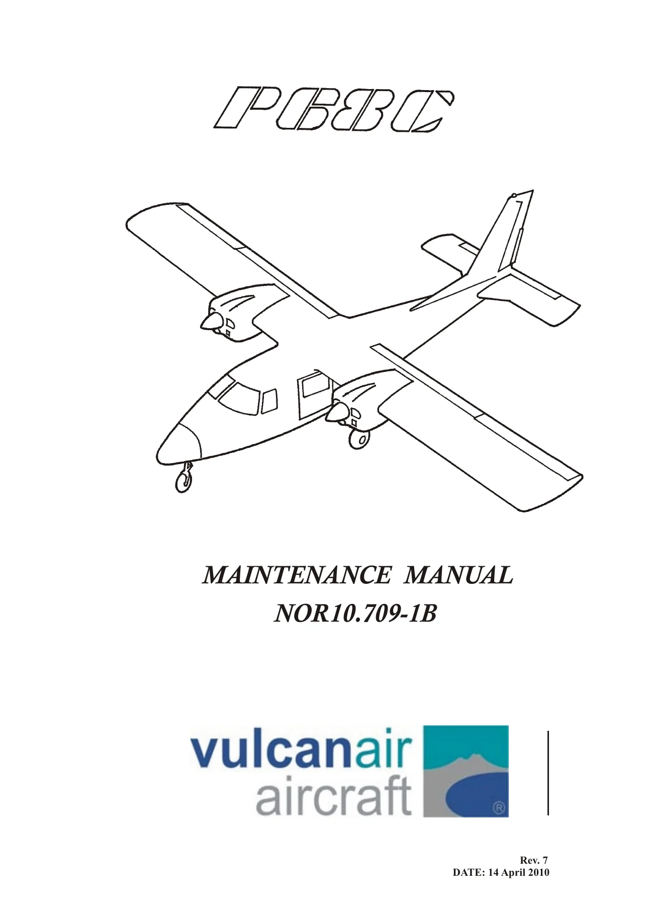
Vulcanair P68C Maintenance Manual NOR10.709-1B Rev 9 – PDF Download
Original price was: $39.95.$24.95Current price is: $24.95.
Complete 350-page Vulcanair P68C aircraft maintenance manual, document NOR10.709-1B at Rev. 9 – ground handling, servicing, inspection charts, structures, flight controls, landing gear, brakes, power plant and systems for the P68C twin.
Description
Vulcanair P68C Maintenance Manual NOR10.709-1B Rev 9 – File Details
- Manual type: Aircraft maintenance manual covering recommended ground handling, servicing and maintenance procedures for continued airworthiness
- Aircraft: P68C seven-place twin-engine high-wing monoplane
- Manufacturer: Vulcanair S.p.A., Naples, Italy
- Document number: NOR10.709-1B
- Revision: Rev. 9, issued 30 August 2017 (revision log runs from Rev. 1 dated 13 Dec. 1983 through Rev. 9)
- Language: English
- Format: PDF
- Length: 350 pages across ten lettered sections plus foreword, list of effective pages, log of revisions, record of temporary revisions and record of applicable service bulletins
Chapters Covered in the P68C Maintenance Manual NOR10.709-1B Rev 9
- Section A – General: introduction, general description, wing, fuselage, empennage, landing gear, brake system, engine and propellers, fuel system, flight controls, cabin heater/windshield defroster/fresh air system, aircraft characteristics and power plant data
- Section B – Ground Handling, Servicing and Inspection: jacking, levelling, weighing, mooring, parking, towing, taxiing; fuel, oil, induction, battery, tire, nose gear shock strut, brake and lubrication servicing; access panels and detachable parts; pre-flight inspection; inspection charts; engine run-up; overlimits inspection; service life limits; continued airworthiness limitations
- Section C – Structures: wing group (wing tip, leading edge, aileron, flap and complete wing removal and installation), fuselage group (windshield, pilot side window, entrance door window and side windows, entrance/baggage/crew doors and their latch and lock assemblies), empennage group (stabilator, torque tube, stabilator trim tab, rudder, rudder trim tab, vertical fin) and control surface balancing procedures
- Section D – Flight Controls: control column, aileron control system, stabilator control system, stabilator trim control system, rudder control system, rudder trim control system and flap control system, including cable removal and installation and full rigging procedures
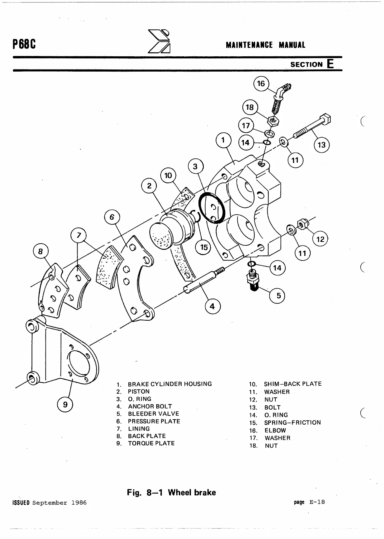
- Section E – Landing Gear and Brake System: main gear, main wheel and axle, main wheel disassembly and assembly, wheel alignment and balancing, nose gear and strut disassembly and assembly, nose wheel, wheel brake disassembly and assembly, brake cylinder removal and installation, brake filling and bleeding
- Section F – Power Plant: engine cowling, propeller removal and installation, propeller cleaning/inspection/repair, blade track check, propeller governor removal, installation and rigging, engine removal and installation, engine shock mount replacement, induction system air filter, ignition system and magnetos, lubrication system, engine fuel system, throttle/mixture/governor control rigging
- Section G – Fuel System
- Section H – Electrical System
- Section I – Instruments and Related Systems
- Section L – Utility and Optional Systems
- Front matter and records: foreword, list of effective pages, log of revisions (Rev. 1 through Rev. 9), record of temporary revisions, record of applicable service bulletins
This Vulcanair P68C maintenance manual is organised so a technician can move from a symptom or a scheduled interval straight to the procedure that resolves it. The lettered sections split the aircraft along practical lines rather than academic ones: Section B carries the ground handling and servicing routines plus the interval-driven inspection charts, while Sections C through F walk through the airframe, the flight control system, the landing gear and brakes, and the power plant in step-by-step removal, installation, rigging and adjustment language. Torque figures, cable tensions, control surface travels, fluid specifications and wear limits are printed alongside the procedures that need them, so the manual functions as a working document on the hangar floor rather than a reference that has to be cross-checked against a separate data book. The revision history is preserved in full, with the amended text marked by a vertical black line in the outer margin and temporary revisions printed on yellow stock, so a reader can see exactly what changed and when.
Ground Handling, Servicing and Scheduled Inspection Content
The P68C is a fixed-gear, twin-engine aircraft, and the servicing section reflects that. Lubrication charts are broken out by assembly – engine, landing gear, flight controls, empennage and fuselage controls – each with its own frequency column and instruction column, running from 100-hour items such as main gear wheel bearings, nose gear steering lever, shimmy dampener and torque link, through 200-hour brake reservoir checks, up to 500-hour and 1000-hour items such as stabilator trim tab actuator screws and control column sprocket bushings.
The inspection programme is laid out in charts with three interval columns plus a special inspection column. A minor inspection is performed every 50 flight hours or at least every 6 months; the 100-hour and 200-hour columns build on top of it, and the special inspection letters reference intervals including every 400 flight hours, every 500 flight hours or at least every 2 years, every 1000 flight hours or at least every 4 years, every 1500 flight hours or at least every 5 years, every 2000 flight hours or at least every 4 years or any time the engine is removed, and every 200 flight hours or at least every 1 year. The chart items are grouped under airframe, landing gear, flight controls, propeller, engine group and optional equipment, so a shop can work through an annual or 100-hour inspection in a logical sequence.
Overlimits inspection coverage is included for three situations owners actually encounter: heavy landing or landing overweight, lightning strike or static discharge, and flight through turbulent air. Each has its own ordered checklist – for a heavy landing this runs from the nose wheel strut upper attachment and nose frame through the main gear spring attachment links, main gear springs, axles, wheels, tires, brake plumbing and brake units, then on to engine mountings, wing skin, wing-to-fuselage fittings and trailing edge components. For a lightning strike the sequence covers skin burns and melting, rivets, bolts, screws and fasteners, anti-static wicks, the electrical system and instruments, avionics and antennae, autopilot harness, magnetic compass, navigation lights and radome – with a specific note that if a strike is found on a propeller, the engine must be removed and overhauled.
Service Life Limits and Overhaul Intervals
The service life limits section lists the sole lifed items with a clear statement that the limits must not be exceeded, and the overhaul and replacement schedule sets out recommended intervals for engines, propellers and governors. Engine overhaul follows Lycoming Service Instruction No. 1009; propeller and governor work follows Hartzell HC-SL-61-61Y; MT-Propeller governors are listed at every 2000 flight hours or 6 years, whichever occurs first; Woodward governors follow Woodward S/B-33580-M rev.12. Airframe items are scheduled separately – for example engine compartment rubber hoses every 2000 flight hours or 5 years, engine tubular mounts at 1800 flight hours for turbocharged aircraft or 2000 flight hours for the reciprocating-engine models, and on-condition items including shimmy damper, wheel axles, spring legs, flap actuator motor, stabilator trim tab actuator, rudder trim actuator and control cables.
Structures, Flight Controls and Landing Gear Work
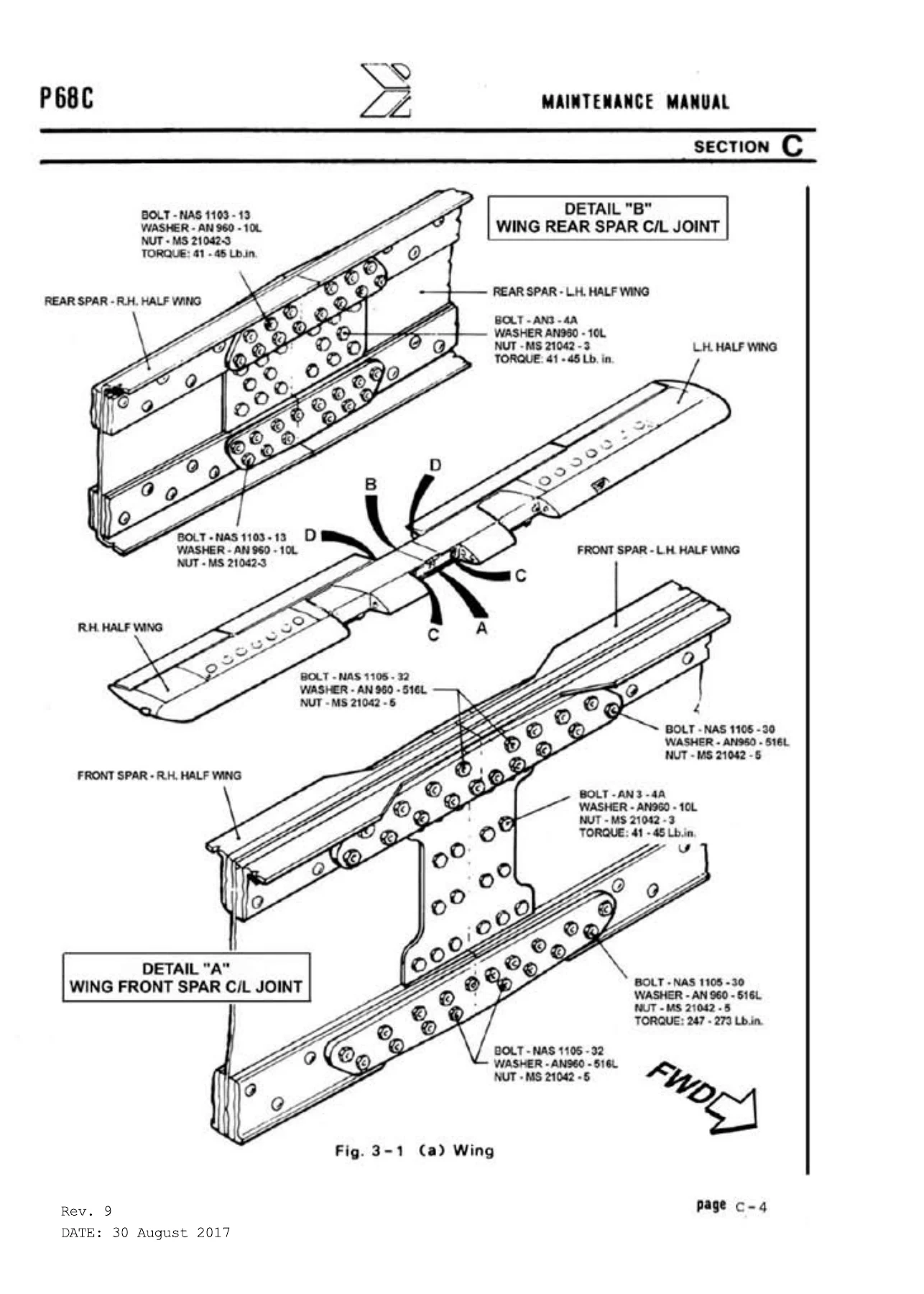
The structures section is written as a removal and installation manual for the airframe. Wing tip and leading edge removal, aileron and flap removal, and complete wing removal are each broken into numbered steps, with the engine-nacelle leading edge treated as a separate procedure from the outboard leading edge. The wing-fuselage attachment is documented with bolt callouts, washer and nut part numbers and torque values for the front and rear spar centre-line joints, and the removal procedure warns about supporting the wing-engine assembly on padded cradles and lifting the engine to the same height as the wing before sliding the attachment bolts.
Control surface balancing is covered in detail for the stabilator, rudder and aileron, with separate procedures for leading-edge-heavy and trailing-edge-heavy conditions, balance check weights and tolerances, drilling limits on mass balance weights, and a factory weight reference for each surface. This is the kind of information that is normally only found in a manufacturer-level document, and it is what makes the manual useful after a repair, repaint or surface replacement.
Flight controls are handled system by system with cable routing, turnbuckle locations, cable guard positions and rigging sequences. The control surface travel and cable tension data is presented together: ailerons up 30 degrees and down 17 degrees with 60 pound cable tension, flaps full down 35 degrees with 150 pound tension, stabilator 16 degrees nose up and 6 degrees nose down with 150 pound tension, rudder 25 degrees each side with 60 pound tension, stabilator trim and rudder trim at 24 pound tension on 1/16 inch cable.
Power Plant and Systems
The power plant section covers the two AVCO Lycoming IO-360-A1B6 four-cylinder, direct-drive, fuel-injected engines rated at 200 HP at 2700 RPM, along with the Hartzell HC-C2YK-2C(F) full-feathering constant-speed propellers using FC7666A-4 blades. Engine removal is written as a practical sequence with a recommendation to remove the engine together with its mount, followed by a reverse-order installation procedure with torque values for the mount bolts and clearance notes for the exhaust.
Engine data in the manual includes compression ratio, firing order, magneto series, spark plug types, alternator and starter ratings, oil sump capacity, oil pressure and temperature limits, and cylinder head temperature limits. Propeller chamber pressure requirements are tabulated against temperature in both Fahrenheit and Celsius, and the propeller specification table gives blade angle settings, dry torque values for the mounting bolts, spinner adaptor nut and spinner attachment screws.
Put the Vulcanair P68C Maintenance Manual NOR10.709-1B Rev 9 to Work
Whether the job is a scheduled 100-hour inspection, a 50-hour minor inspection, a landing gear strut reseal, a brake bleed, a flap rigging adjustment, a stabilator rebalance after repair, or an engine removal, this P68C maintenance manual gives the procedure, the specification and the limits in one place. Correct torque values, cable tensions and control travels matter on a twin-engine aircraft – a stabilator rigged outside its travel limits or a flap cable tensioned to the wrong figure does not simply fly badly, it fails an inspection or behaves unpredictably in the air. Having the manufacturer figures to hand removes guesswork and gives a documented basis for the work.
The file is delivered instantly as a PDF after payment. There is no shipping, no waiting for a printed binder to arrive, and no restriction on where you use it – open it on a laptop or tablet in the hangar, or print the specific pages you need for the job at hand and keep the rest clean. Search, zoom and print from the same file, and keep it on hand for every future inspection on the aircraft.
IMAGES PREVIEW
Reviews
There are no reviews yet.