
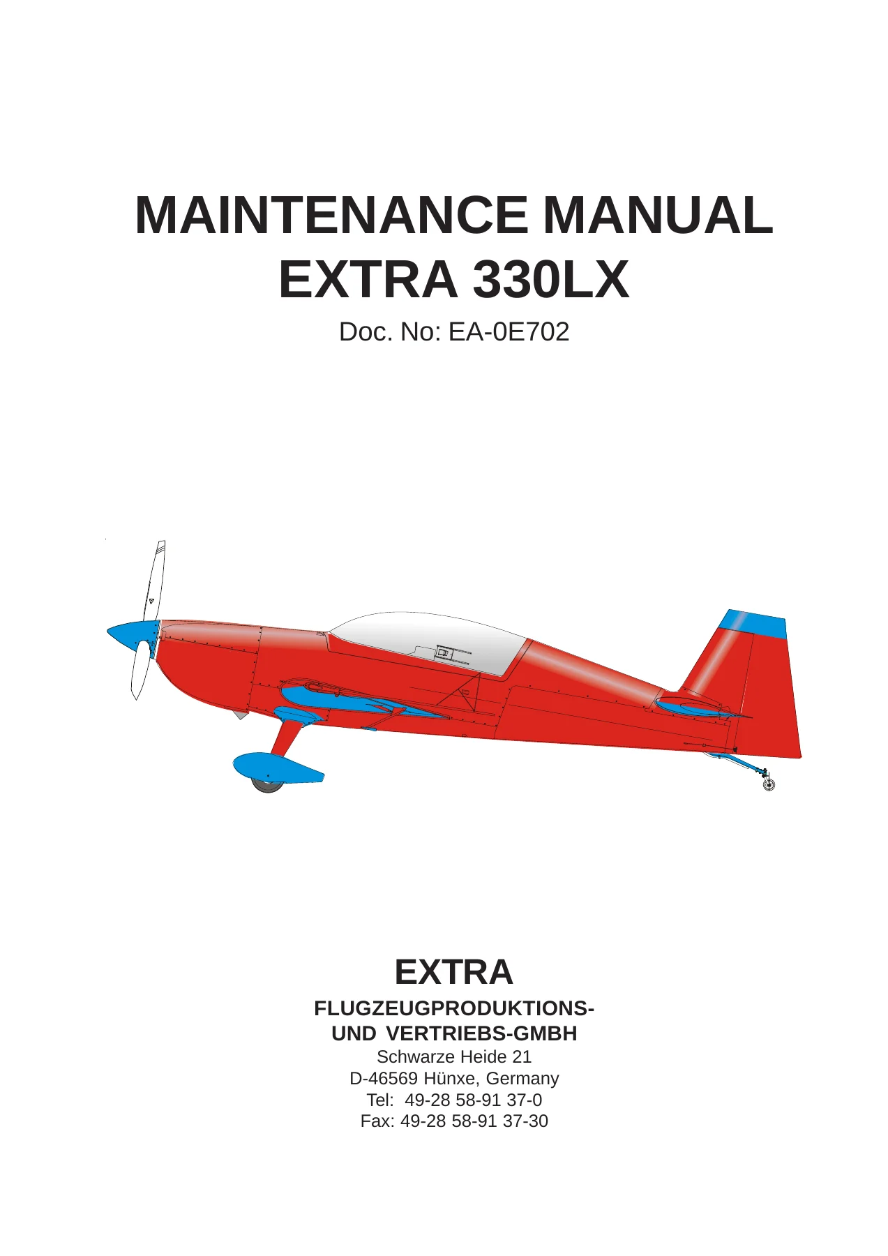
EXTRA 330LX Aircraft Maintenance Manual EA-0E702 – 2017 Revision 5 PDF
Original price was: $44.95.$26.95Current price is: $26.95.
Complete EXTRA 330LX maintenance manual, Doc. No. EA-0E702, 2nd Edition Revision 5 dated 15 March 2017. Covers the airframe, Lycoming AEIO-580-B1A powerplant, MT-Propeller, flight controls, fuel, landing gear, electrical system, structures, repair of composite parts, scheduled inspection checklists and airworthiness limitations for the aerobatic EXTRA 330LX.
Description
EXTRA 330LX Maintenance Manual – Doc. No. EA-0E702
This is the full EXTRA 330LX maintenance manual issued by EXTRA Flugzeugproduktions- und Vertriebs-GmbH, the manufacturer of the aircraft. The document carries Doc. No. EA-0E702 and is the 2nd Edition, Revision 5, dated 15 March 2017. Its technical content is approved under the authority of DOA ref. EASA.21J.073. It is written for educated maintenance staff and licensed personnel who service, inspect, repair and return the EXTRA 330LX to an airworthy condition.
File Details
- Manual type: Aircraft maintenance manual
- Brand / manufacturer: EXTRA Flugzeugproduktions- und Vertriebs-GmbH, Schwarze Heide 21, D-46569 Hünxe, Germany
- Model covered: EXTRA 330LX
- Document number: EA-0E702
- Edition: 2nd Edition
- Revision: Revision 5
- Date: 15 March 2017
- Approval: Technical content approved under DOA N° EASA.21J.073
- Language: English
- File format: PDF
Chapters Covered
- Chapter 1 – Introduction: related documents, trade marks, safety
- Chapter 2 – How to Use the Service Manual: manual set-up, chapter set-up, page and figure numbering, layout, notes and safety notes, handling, revisions, service bulletins, checklists
- Chapter 3 – General Description: construction, flight control system, brake system, powerplant, fuel system, electrical system, instruments
- Chapter 4 – Airworthiness Limitations: temperature limit, operating time, life limited components, replacement times
- Chapter 5 – Time Limits / Maintenance Checks: overhaul schedule, recommended replacement times, time between inspection, 25 hour engine and aircraft inspection, scheduled maintenance checks, significant items inspection, unscheduled maintenance checks
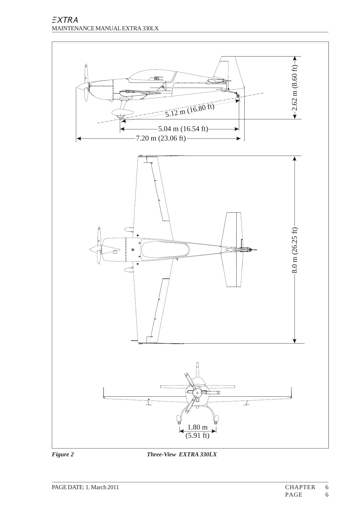
- Chapter 6 – Dimensions and Areas: main dimensions, wing, horizontal tail, elevator, vertical tail, rudder, three-view
- Chapter 7 – Lifting and Shoring: balance weight, shoring the front, shoring the tail
- Chapter 8 – Leveling and Weighing: weighing and calculation of centre of gravity, leveling
- Chapter 9 – Towing and Taxiing
- Chapter 10 – Parking, Mooring, Storage and Return to Service
- Chapter 12 – Servicing: refueling, defueling, fuel drains, engine oil replenishment and oil change, brake fluid, tire inflation, exterior and interior cleaning, engine cleaning, removal of snow and ice
- Chapter 20 – Standard Practices – Airframe: bolt types, width across flats, torque values, special torque values, measuring techniques, coin tapping, flexible hoses, fittings, control cables, PR-812, assembly after container shipping
- Chapter 21 – Air Conditioning: heating system, inlet box, distribution box, Bowden cables
- Chapter 23 – Communications: speech communication, VHF whip antenna
- Chapter 24 – Electrical Power: DC generation, battery system, alternator system, drive belt, pulley, system ground, DC load distribution, circuit breakers, switches, relays
- Chapter 25 – Equipment and Furnishings: front seat, rear seat, seat belts, aircraft document bag
- Chapter 27 – Flight Controls: general, control rods, bellcranks, front and rear control stick, torque tube, aileron control, spades, rudder control, bottom hinge bracket and bellcranks, control cable, fairlead, elevator control, trim tab
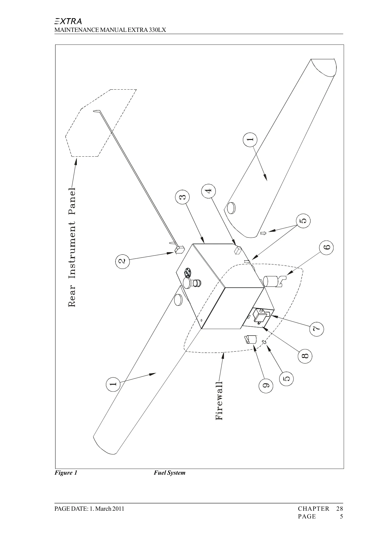
- Chapter 28 – Fuel: storage, center tank, acro tank, acro tank flop tube, wing tank inspection door, wing tank outlets, filler necks, ventilation line, distribution, fuel selector valve, gascolator, boost pumps, fuel lines, indicating, fuel quantity transducer, float wire
- Chapter 31 – Indication / Recording System: rear instrument panel, rear instrument cover, front instrument panel, panel frame, Garmin G5, typical instruments
- Chapter 32 – Landing Gear: main landing gear, mounting clamp, wheel axis, tail spring, tail wheel fork, wheels and brakes, master cylinder, wheel fairing, tail wheel
- Chapter 33 – Lights: low voltage monitor, navigation / strobe light system, LED navigation / strobe system, landing light, head lamp
- Chapter 34 – Navigation: pitot / static system, altimeter, airspeed indicator, pitot-static tube, magnetic compass, attitude indicator, transponder, blind encoder
- Chapter 51 – Standard Practices and Structures – General: access panel identification, damage classification, repair criteria, composite parts, metal components, aluminium components, control surface balancing, repairs of laminates, sandwich material and spars, painting, refinishing, re-bonding of bushings
- Chapter 53 – Fuselage: steel tube design, canopy, canopy glass, main fuselage cover, bottom fuselage cover, layer sequences
- Chapter 55 – Stabilizers: horizontal stabilizer, elevator, vertical stabilizer, rudder
- Chapter 57 – Wings: wing removal and installation, wing tip, ailerons
- Chapter 61 – Propeller: propeller, controlling, governor, RPM vernier control cable
- Chapter 71 – Power Plant: cowling, engine mount, shock mounts, air baffles
- Chapter 72 – Engine: general, troubleshooting, engine removal and installation
- Chapter 73 – Engine Fuel and Control: throttle, throttle control cable, rear and front throttle control levers, mixture, mixture vernier control cable, fuel pressure indicating
- Chapter 77 – Engine Indicating: RPM, manifold pressure, CHT, EGT, integrated engine instrument systems, Electronics International MVP-50P
- Chapter 78 – Exhaust: collector / nozzle, exhaust pipe, muffler, gasket, heat shield
- Chapter 79 – Oil System: Christen inverted oil system, valve balls, oil cooler, fittings, flexible hoses, oil pressure and oil temperature indicating
- Chapter 91 – Charts: electrical system schematics and wiring diagrams by serial range
- Chapter 96 – Smoke: smoke system storage, main tank, acro tank, distribution
Altogether the manual forms a complete maintenance library for the EXTRA 330LX. Instead of isolated procedures, a technician gets the manufacturer’s own removal, installation, rigging, adjustment and repair method for every major assembly, plus the torque tables, tolerances and measurement techniques those procedures depend on. Composite repair is treated as a discipline of its own, with damage classification, scarf ratios, wet lay-up methods, vacuum bagging and curing cycles spelled out. The airworthiness limitations chapter sets the life limits and mandatory replacement times that must not be exceeded, while the scheduled maintenance chapter turns all of that into checklists that can be worked through at 25, 50, 100, 200, 300, 400, 500 and 1000 hour intervals.
Airframe, Structures and Composite Repair
The EXTRA 330LX is a lightweight two-seat low-wing monoplane built from composite and steel materials, with a steel tube fuselage, a one-piece dual chamber carbon fibre main spar wing, honeycomb sandwich shells, and a fixed glass-fibre main landing gear spring. This manual documents those structures in detail: layer sequences for the wing, fuselage covers, cowlings, wheel fairings, stabilizers, elevator, rudder and ailerons; the specific fabrics and resins approved for repair; damage classes 1 to 4 and the limits of what may be repaired in the field; and step-by-step scarf, backing plate and vacuum bagging procedures. There are also dedicated procedures for re-bonding loose empennage attachment bushings and wing main spar flange bushings, including cure cycles. Access panel identification, lifting and shoring, leveling and weighing, and centre of gravity calculation are all covered, so the airframe work is fully supported from the ground up.
Powerplant, Propeller and Systems
The powerplant chapter set covers the Lycoming AEIO-580-B1A installation with its inverted flight oil system, the Gomolzig six-into-one exhaust with integrated muffler, the Bendix RSA-10 fuel injection system, magneto ignition with Slick Start booster, and the Christen inverted oil system with its gravity-operated ball valves. The propeller chapters handle the MT-Propeller constant speed installation and its governor, together with the RPM vernier control cable removal, installation and rigging. The electrical section includes the battery and alternator systems, the drive belt tension check by torque method, the electrical main board, DC load distribution, and a full set of serial-number-specific wiring schematics in the charts chapter.
Maintenance Intervals, Torque Data and Life Limits
The manual provides standard torque values for metric and inch fasteners, plus special torque values for the main landing gear clamp, engine mount, longeron cutout bridge, stabilizer spar bolts and wing main spar safety bolts. Airworthiness limitations list 6000 hour replacement times for the wing, aileron, vertical stabilizer, rudder, horizontal stabilizer, elevator and landing gear spring, and set a composite structure temperature limit of 72 degrees C (162 degrees F). The scheduled maintenance schedule combines operational engine checks with aircraft checks, and the 1000 hour significant items inspection releases the aircraft for a further 1000 hours up to the 6000 hour limit.
Why This EXTRA 330LX Maintenance Manual Matters
An aerobatic aircraft is stressed far beyond normal category limits every time it flies, and the EXTRA 330LX is no exception. Correct rigging of the aileron, elevator and rudder control systems, correct torque on the spar and stabilizer attachment bolts, correct balance of the control surfaces, and correct repair of composite structure are what keep the aircraft safe. This EXTRA 330LX maintenance manual gives the technician the manufacturer’s own figures and procedures for all of it, so inspections, repairs and adjustments can be carried out to the standard the aircraft was designed for. It supports annual inspections, 25 hour oil changes, 100 hour checks, the 1000 hour significant items inspection, brake fluid replenishment, wheel and brake servicing, fuel tank and selector valve work, and unscheduled checks after a propeller strike, hard landing, engine fire or lightning strike.
The file is delivered instantly as a PDF after payment. There is no shipping and nothing to wait for, and the manual can be read on a workshop computer, a tablet or a phone, or printed page by page for use at the aircraft. Keep it on hand in the hangar and every torque value, inspection interval and repair procedure for the EXTRA 330LX is one search away.
IMAGES PREVIEW
Reviews
There are no reviews yet.