
Airbus A320 Aircraft Characteristics Airport and Maintenance Planning Manual – A320-200 & A320neo PDF
Original price was: $39.95.$23.95Current price is: $23.95.
Airbus A320 Aircraft Characteristics – Airport and Maintenance Planning (AC) manual, Revision 31, covering A320-200 and A320neo airport planning, ground maneuvering, terminal servicing, engine exhaust data, and pavement requirements.
Description
Airbus A320 Aircraft Characteristics – Airport and Maintenance Planning (AC) Manual
The Airbus A320 Aircraft Characteristics – Airport and Maintenance Planning (AC) manual is the comprehensive planning document issued for the A320-200 series and A320neo family, covering aircraft equipped with wing-tip fences or sharklets. Revision 31, dated May 01/16, consolidates the data airport operators, airlines, and Maintenance/Repair Organizations need for airport infrastructure planning, ramp operations, and maintenance facility design.
This is the exact reference used to align ground support equipment, pavement design, gate layouts, and turn-round procedures with the physical and performance characteristics of the A320. If you’re planning airport facilities, writing handling procedures, or verifying clearances, this Airport and Maintenance Planning manual is the primary source.
File Details
- Manual type: Aircraft Characteristics – Airport and Maintenance Planning (AC)
- Brand: Airbus
- Models covered: A320-200, A320neo
- Engines covered: CFM56 Series, IAE V2500 Series, CFM LEAP-1A, PW 1100G
- Revision: Revision No. 31
- Revision date: May 01/16
- Language: English
- File format: PDF
- Page count: 387 pages
Chapters Covered
The manual follows the standard Airbus AC structure, moving from aircraft description through performance, ground handling, and pavement engineering data:
- 1 – Scope — Introduction, Glossary
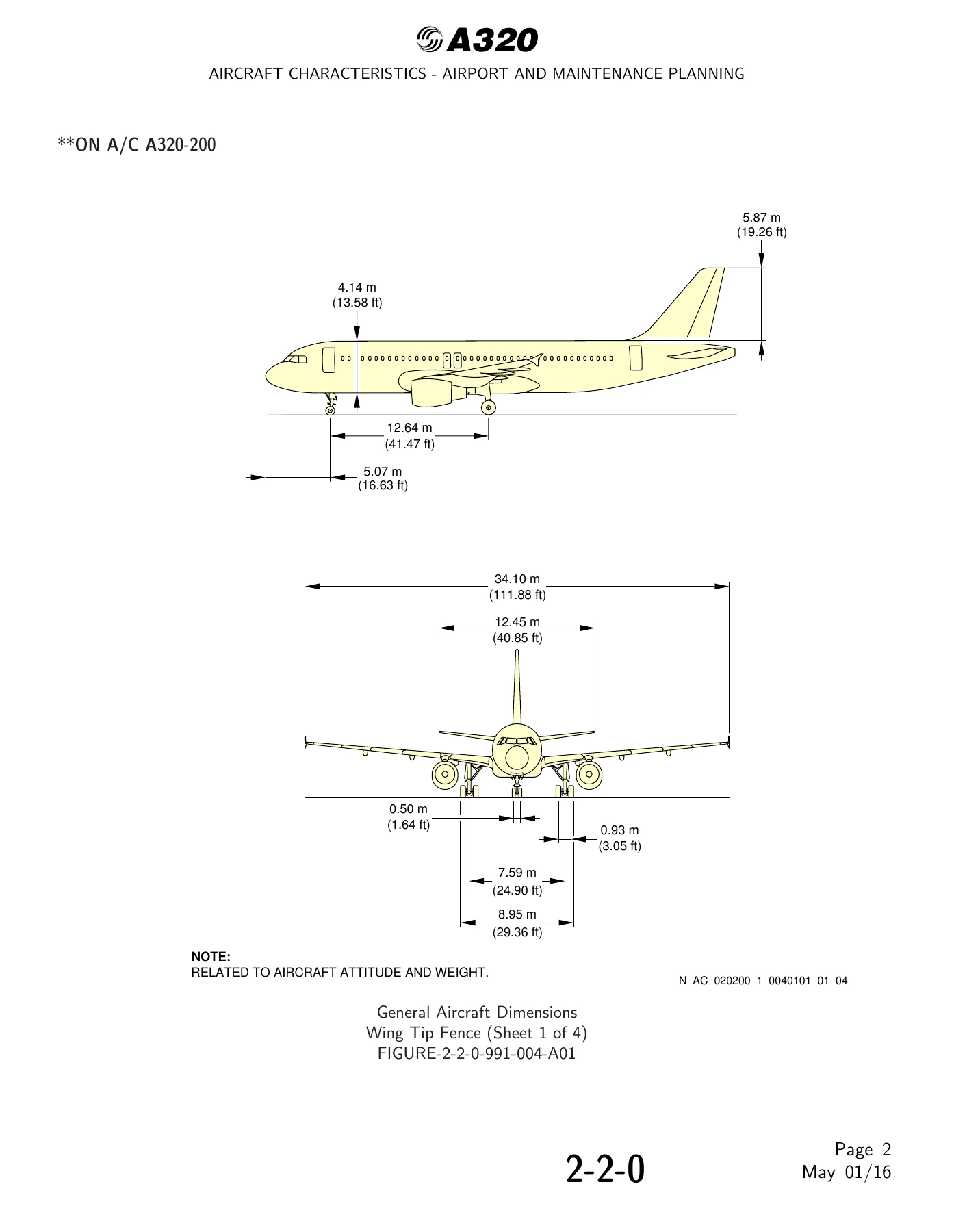
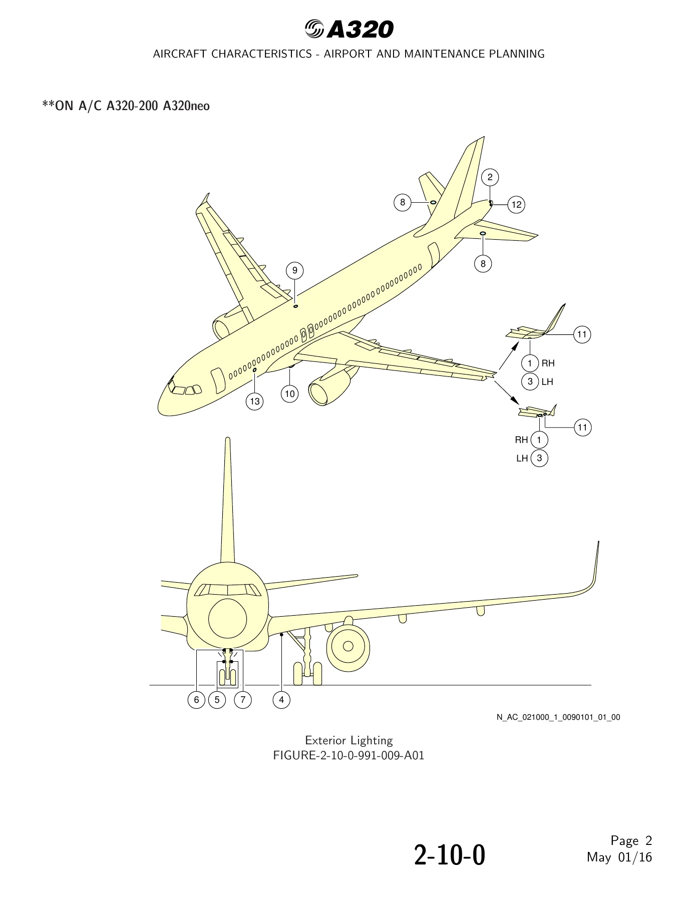
- 2 – Aircraft Description — General Aircraft Characteristics Data, General Aircraft Dimensions, Ground Clearances, Interior Arrangements (Plan View and Cross Section), Cargo Compartments, Door Clearances and Location, Escape Slides, Landing Gear, Exterior Lighting, Antennas and Probes Location, Power Plant, Leveling/Symmetry/Alignment, Jacking
- 3 – Aircraft Performance — General Information, Payload/Range (ISA), Take-Off Weight Limitation (ISA and ISA+15°C), Landing Field Length (ISA), Final Approach Speed
- 4 – Ground Maneuvering — Turning Radii, Minimum Turning Radii, Visibility from Cockpit, Runway and Taxiway Turn Paths (135°, 90°, 180° turns), Runway Holding Bay, Minimum Line-Up Distance Corrections, Aircraft Mooring
- 5 – Terminal Servicing — Aircraft Servicing Arrangements, Typical Ramp Layouts (Open Apron and Gate), Full Servicing and Outstation Turn Round Time Charts, Ground Service Connections, Grounding Points, Hydraulic/Electrical/Oxygen/Fuel/Pneumatic/Oil/Potable Water/Waste Water Systems, Engine Starting Pneumatic Requirements, Ground Pneumatic Power Requirements, Preconditioned Airflow Requirements, Ground Towing Requirements, De-Icing and External Cleaning
- 6 – Operating Conditions — Engine Exhaust Velocities and Temperatures (Ground Idle, Breakaway, Takeoff), Danger Areas of Engines, APU
- 7 – Pavement Data — Landing Gear Footprint, Maximum Pavement Loads, Landing Gear Loading on Pavement, Flexible Pavement Requirements (US Army Corps of Engineers and LCN), Rigid Pavement Requirements (PCA and LCN), ACN/PCN Reporting System
- 8 – Scaled Drawings
- 10 – Aircraft Rescue and Fire Fighting — Hazardous Materials, Batteries, Wheel/Brake Overheat, Composite Materials, Emergency Evacuation Devices, Doors, Cargo Doors, Control Panels, Ground Clearances, Structural Break-in Points
What This Airport and Maintenance Planning Manual Delivers
Airbus built this document around the daily reality of moving, servicing, and parking an A320 on a commercial airport. It’s divided between aircraft-description data — external dimensions, door sill heights, ground clearances for the tailplane, wings, engines, and landing gear — and operational planning data covering turning radii, cockpit visibility, taxiway turn paths, and minimum line-up distance corrections.
The servicing chapters are dense with actual connector locations and specifications. Hydraulic system ground service panels for the Green, Blue, and Yellow systems list access door numbers and distances from the aircraft centerline and aft of nose. Fuel system coverage includes refuel/defuel couplings, overpressure protectors, NACA vent intakes, and overwing gravity-refuel caps. Engine starting pneumatic requirements, ground pneumatic power for heating and cooling, and preconditioned airflow settings are charted for each engine option — CFM56, IAE V2500, CFM LEAP-1A, and PW 1100G. Ground towing requirements include drawbar pull charts based on aircraft weight, engines at idle, and slope.
The pavement data chapter is engineering-grade. It contains maximum pavement loads at forward and aft CG, landing gear loading on flexible and rigid pavement, and complete ACN/PCN reporting tables broken down by weight variant and tire pressure. The weight variants covered span WV000 through WV018 for the A320-200 and WV050 through WV057 for the A320neo. Tire pressures, main and nose gear footprints, and the bogie landing gear variant are all documented.
Why This Manual Matters
Airport planning decisions are only as good as the data behind them. Gate layouts, pushback procedures, pavement thickness, and ramp equipment positioning all depend on the actual numbers in this AC manual. Using outdated or incomplete aircraft characteristics leads to insufficient clearances, pavement overstress, and unsafe servicing positions. The revision-tracked content in Revision 31 gives you the correct dimensions and load figures for the weight variant and engine option you’re actually operating.
For MRO and maintenance planning, the jacking chapters show primary and auxiliary jacking points, jacking designs, shoring cradle locations, and the load at each aircraft jacking point by CG position. The landing gear maintenance pit envelopes and NLG/MLG jacking diagrams make hangar and dock planning practical rather than theoretical.
IMAGES PREVIEW
Instant PDF Delivery
After payment you receive the complete Airbus A320 Aircraft Characteristics – Airport and Maintenance Planning manual as a PDF, ready to open on any device. No shipping, no waiting. Print the pages you need for the ramp, the planning office, or the maintenance dock — the airport dimensions, turn path diagrams, and pavement charts are all reproduced page for page.

Reviews
There are no reviews yet.