
Airbus A320 AC Airport and Maintenance Planning Manual – A320-200 & A320neo PDF
Original price was: $39.95.$24.95Current price is: $24.95.
Airbus A320 Aircraft Characteristics – Airport and Maintenance Planning (AC) manual, Revision 37 dated Nov 01/19, covering the A320-200 and A320neo with CFM56, IAE V2500, CFM LEAP-1A and PW 1100G engine data. 399-page PDF for airport planners, airlines and MRO facilities.
Description
Airbus A320 Aircraft Characteristics – Airport and Maintenance Planning Manual
The Airbus A320 Aircraft Characteristics – Airport and Maintenance Planning (AC) manual is the controlled reference document airport operators, airlines and Maintenance/Repair Organizations use to plan everything that happens to an A320 on the ground. This Revision No. 37 issue, dated Nov 01/19, covers the A320-200 series equipped with wing-tip fences or sharklets together with the A320neo, and it consolidates aircraft geometry, ground clearances, pavement loading, terminal servicing and rescue/fire-fighting data into one publication.
Because the AC manual is written for facility planning rather than line maintenance, it carries the numbers that airports and MROs actually need to design aprons, size pavements, position ground support equipment and lay out turn-round operations. This Airbus A320 AC Airport and Maintenance Planning Manual covers every operational weight variant of the A320-200 and A320neo and presents the data in tables, dimensioned drawings and graphs rather than dense text.
File Details
- Manual type: Aircraft Characteristics – Airport and Maintenance Planning (AC)
- Manufacturer: Airbus
- Models covered: A320-200, A320neo
- Engine coverage: CFM56 Series, IAE V2500 Series, CFM LEAP-1A, PW 1100G
- Revision: No. 37
- Revision date: Nov 01/19
- Edition year: 2020
- Language: English
- Page count: 399
- File format: PDF
Chapters Covered
- 1 – Scope: Introduction, Glossary
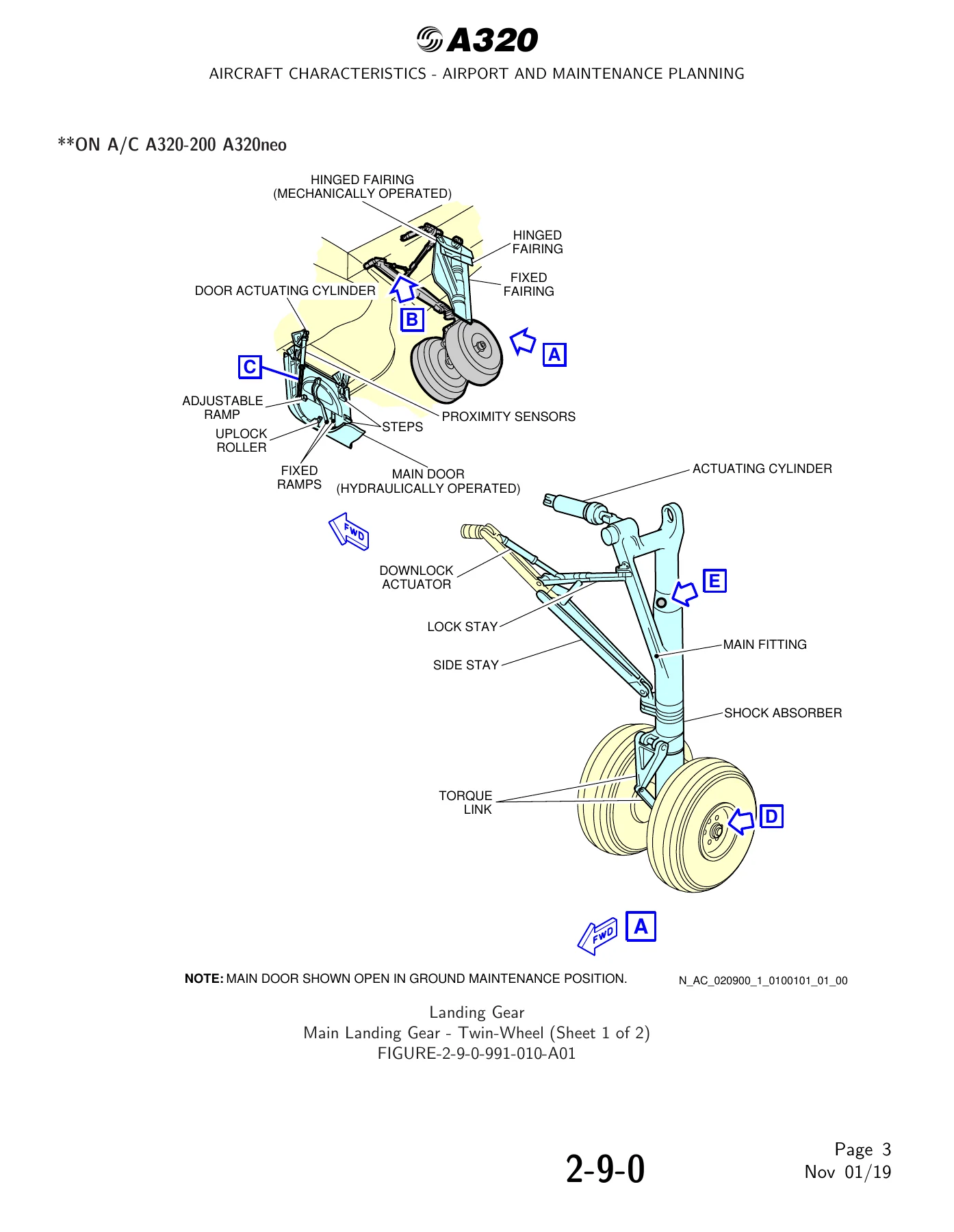
- 2 – Aircraft Description: General Aircraft Characteristics Data, General Aircraft Dimensions, Ground Clearances, Interior Arrangements – Plan View, Interior Arrangements – Cross Section, Cargo Compartments, Door Clearances and Location, Escape Slides, Landing Gear, Exterior Lighting, Antennas and Probes Location, Power Plant, Leveling/Symmetry and Alignment, Jacking
- 3 – Aircraft Performance: General Information, Payload/Range – ISA Conditions, Take-off Weight Limitation – ISA Conditions, Take-off Weight Limitation – ISA +15 degrees C Conditions, Aerodrome Reference Code, Landing Field Length – ISA Conditions, Final Approach Speed
- 4 – Ground Maneuvering: General Information, Turning Radii, Minimum Turning Radii, Visibility from Cockpit in Static Position, Runway and Taxiway Turn Paths, Runway Holding Bay (Apron), Minimum Line-Up Distance Corrections, Aircraft Mooring
- 5 – Terminal Servicing: Aircraft Servicing Arrangements, Typical Ramp Layout – Open Apron, Typical Ramp Layout – Gate, Terminal Operations – Full Servicing Turn Round Time, Terminal Operations – Outstation Turn Round Time, Ground Service Connections, Grounding Points, Hydraulic System, Electrical System, Oxygen System, Fuel System, Pneumatic System, Oil System, Potable Water System, Waste Water System, Engine Starting Pneumatic Requirements, Ground Pneumatic Power Requirements, Preconditioned Airflow Requirements, Ground Towing Requirements, De-Icing and External Cleaning
- 6 – Operating Conditions: Engine Exhaust Velocities and Temperatures, Danger Areas of Engines, APU
- 7 – Pavement Data: General Information, Landing Gear Footprint, Maximum Pavement Loads, Landing Gear Loading on Pavement, Flexible Pavement Requirements – U.S. Army Corps of Engineers Design Method, Flexible Pavement Requirements – LCN Conversion, Rigid Pavement Requirements – Portland Cement Association Design Method, Rigid Pavement Requirements – LCN Conversion, Aircraft Classification Number – Flexible and Rigid Pavements
- 8 – Scaled Drawings
- 10 – Aircraft Rescue and Fire Fighting
Read as a whole, this A320 airport and maintenance planning manual gives a planner a complete working picture of the aircraft on the ground. Chapter 2 establishes the physical baseline, with general aircraft dimensions for both wing-tip fence and sharklet configurations, ground clearance tables at maintenance weight, maximum ramp weight forward CG and aft CG, and jacked configurations. Chapter 3 supplies the performance side of the equation with payload/range curves, take-off weight limitation graphs at ISA and ISA +15 degrees C, landing field length and final approach speed, plus the aerodrome reference code classification that determines which runways and taxiways the type can use.
A320-200 and A320neo Weight Variants
The general aircraft characteristics tables break the fleet down by weight variant rather than by a single generic figure. For the A320-200 the document lists WV000 through WV019, with maximum ramp weights running from 66 400 kg (146 387 lb) on WV006 up to 78 400 kg (172 842 lb) on WV015. The A320neo variants start at WV050 and extend through WV085, with maximum ramp weights from 70 400 kg (155 205 lb) up to 79 400 kg (175 047 lb). Each variant carries its own maximum take-off weight, maximum landing weight and maximum zero fuel weight, so anyone using this data for pavement or facility planning can select the exact weight variant they operate instead of approximating.
Common characteristics across both models include a standard single-class seating capacity of 180, usable fuel capacity of 23 859 l, 26 759 l or 29 659 l depending on ACT option, a pressurized fuselage volume of 330 m3 and a passenger compartment volume of 139 m3. Cargo hold usable volumes are given separately for the forward, aft and bulk compartments, along with the water volumes for each.
Ground Maneuvering and Terminal Servicing Data
Chapter 4 is built around turning capability. It gives turning radii with no slip angle for both dual and bogie landing gear, minimum turning radii at maximum steering angle, cockpit visibility angles in the static position, and worked 90 degree, 135 degree and 180 degree turn paths with the FAA lead-in fillet and taxiway radii dimensioned on each drawing. Minimum line-up distance corrections on TODA and ASDA are tabulated for runway entry and for 180 degree turns on turn pads and on 30 m, 45 m and 60 m runways.
Chapter 5 covers terminal servicing in detail. It includes typical ramp layouts for open apron bulk loading, open apron ULD loading and gate operations, full servicing and outstation turn-round time charts, and the complete ground service connections layout. Every connection point is located by distance aft of nose, distance from aircraft centerline, side and mean height from ground: hydraulic system access doors and accumulators, external power receptacle, oxygen replenishment, refuel/defuel panel and couplings, overpressure protectors and NACA vent intake, high and low pressure pneumatic connectors, engine and IDG and starter oil servicing for each engine type, APU oil, potable water service and drain panels, and the waste water service panel. Grounding points on the nose and main landing gear legs are also tabulated, with alternative grounding points for jacked aircraft.
Operating Conditions, Pavement and Rescue Data
Chapter 6 provides engine exhaust velocity and temperature contours at ground idle, breakaway and takeoff power for each engine option, and then converts them into the danger area diagrams used to set jet blast and intake suction boundaries on an apron. The same treatment is given to the APU. Chapter 7 is the pavement engineering section: landing gear footprint and tire pressures for every weight variant, maximum pavement loads including the braked main gear condition, landing gear loading on pavement graphs, flexible pavement requirements to the U.S. Army Corps of Engineers method, rigid pavement requirements to the Portland Cement Association method, and the ACN table for both flexible and rigid subgrades.
Chapter 8 holds the scaled drawings and Chapter 10 is the aircraft rescue and fire fighting section, with highly flammable and hazardous materials and components, battery location and access, wheel and brake overheat safety areas, composite materials, landing gear ground lock safety devices, emergency evacuation devices, passenger and crew doors, emergency exit hatches, forward and aft lower deck cargo doors, control panels, APU access door, aircraft ground clearances and structural break-in points.
What This Airbus A320 AC Manual Lets You Do
With this manual in hand you can size and lay out an apron stand around the A320 footprint, check that a proposed taxiway fillet actually clears the wingtip, calculate whether an existing pavement can take the aircraft at a given weight variant, position ground support equipment correctly at each service door and connection, and set safe jet blast and intake danger boundaries before anyone walks the ramp. MRO planners get the jacking point locations and load limits, shoring cradle positions, landing gear maintenance pit envelopes and ground towing drawbar pull requirements needed to stand up maintenance facilities.
Getting these numbers right matters because they are interdependent. A stand designed around the wrong weight variant produces pavement loads that do not match the ACN value, and a taxiway turn calculated without the correct minimum turning radius leaves the wingtip outside the graded area. This manual presents the values as the manufacturer published them, tied to specific weight variants and specific engine installations, so the planning figures stay internally consistent.
IMAGES PREVIEW
Instant PDF Delivery
This A320 aircraft characteristics and maintenance planning manual is supplied as an instant-download PDF, so there is no shipping, no waiting and no physical binder to lose. Open it on a laptop at the planning desk, on a tablet during a site walk, or print the specific dimensioned drawing or load table you need for a facilities meeting. The chapter and subject structure makes it straightforward to jump directly to the section that covers the question in front of you.

Reviews
There are no reviews yet.