★ TRUSTED BY 321,897+ PROFESSIONALS WORLDWIDE
🏒
Trusted Business
Verified & Licensed
πŸ›‘οΈ
Virus Free Files
100% Safe Downloads
πŸ”’
Secure Payment
SSL Protected
⚑
Instant Delivery
Available Immediately
Sale!

Gulfstream G200 Pilot Training Manual – Aircraft Systems Volume 2 Second Edition PDF

Original price was: $39.95.Current price is: $24.95.

FlightSafety International Gulfstream G200 Pilot Training Manual, Volume 2: Aircraft Systems, Second Edition, Rev 2.4. A comprehensive illustrated systems guide covering every major aircraft system from electrical power and fuel to avionics, hydraulics, flight controls, and pressurization.

⚑
Instant PDF Download
Available immediately
πŸ’Ύ
Save to Your Device
Download & keep forever
πŸ›‘οΈ
Antivirus Scanned
100% virus-free
🌍
Trusted Worldwide
175,000+ customers

Description

Gulfstream G200 Pilot Training Manual – Volume 2: Aircraft Systems

This is the FlightSafety International Gulfstream G200 Pilot Training Manual, Volume 2: Aircraft Systems, Second Edition, current to Revision 2.4 dated November 2023. It is a systems-focused training document prepared for the Gulfstream G200 business jet, built around the aircraft and avionics manufacturers’ manuals. Rather than a quick-reference card or a marketing brochure, this is a full instructional text used in structured pilot ground training at FlightSafety learning centers.

If you fly, maintain, or study the Gulfstream G200, this manual gives you a guided walkthrough of how the aircraft’s major systems are built, how they interact, what the cockpit indications mean, and how each system behaves in normal, abnormal, and emergency operation. Every chapter is heavily illustrated with schematics, cutaway drawings, panel layouts, EICAS displays, and system flow diagrams.

File Details

  • Manual type: Pilot Training Manual (Aircraft Systems)
  • Manufacturer / publisher: FlightSafety International
  • Aircraft: Gulfstream G200
  • Volume: Volume 2 β€” Aircraft Systems
  • Edition: Second Edition
  • Revision: Rev 2.4, November 2023
  • Original edition: February 2005
  • Language: English
  • Page count: Approximately 478 pages
  • File format: PDF
  • Training locations referenced: DFW Learning Center (DFW Airport, Texas) and Columbus Learning Center (Port Columbus International Airport, Ohio)

Chapters Covered

The table of contents spans seventeen technical chapters plus a Crew Resource Management section and an Answers to Questions section. Top-level chapter coverage includes:

  • Chapter 1 β€” Aircraft General: aircraft dimensions, airplane structure and sections, nose and wing structure, interior arrangement, cabin door, baggage compartment, danger zones, deicer boots, hydraulic system overview, steering, secondary flight controls, Krueger flap, avionics overview
  • Chapter 2 β€” Electrical Power Systems: basic DC schematic, overhead panel controls, DC electrical switches schematic, circuit breakers, EICAS warning and caution messages, EICAS electrical page, DC electrical system during normal operation, DC external power
  • Chapter 3 β€” Lighting: general description, interior lights, exterior lights, emergency lights, controls and indications for each group
  • Chapter 4 β€” Master Warning System: EICAS block diagram, EICAS controls and displays, display control panel, reversionary switching panel, primary page, engine start mode, extended CAS, cruise page, secondary page, electrical page
  • Chapter 5 β€” Fuel System: fuel storage system, fuel distribution system, refueling and defueling, fuel quantity system, controls and indications, system operation
  • Chapter 6 β€” Auxiliary Power Unit: installed APU, APU controls and indicators, maintenance panel controls, EICAS messages, APU starting schedule, in-flight load limits
  • Chapter 7 β€” Powerplant: engine description and major sections, oil system, fuel system, thrust management system, auto throttle system, electronic engine control, engine starting, engine idle, forward thrust, engine synchronization, automatic power reserve, engine shutdown, thrust reverser operation, controls and indications, limitations
  • Chapter 8 β€” Fire Protection: engine fire/overheat protection, APU compartment detection, baggage compartment, engine fire control module, fire extinguishing, detectors, bottles, thermal relief valve, portable extinguishers, controls and indications
  • Chapter 9 β€” Pneumatics: bleed-air system, component description, pneumatic subsystems, bleed-air leak detection, ram-air system
  • Chapter 10 β€” Ice and Rain Protection: ice and rain subsystems, pneumatic boots, windshield heating and rain removal, probe heating, ice detection, baggage compartment heating
  • Chapter 11 β€” Air Conditioning: environmental control unit, temperature control, distribution, controls and indications, EICAS indications
  • Chapter 12 β€” Pressurization: cabin pressure control system in automatic and manual modes, baggage compartment pressurization, outflow valve, cabin pressure controller, safety relief valve, controls and indications, ground/takeoff/climb/cruise/descent/landing modes
  • Chapter 13 β€” Hydraulic Power System: right and left hydraulic systems, reservoirs, engine-driven pumps, pressure and return filters, air-pressure regulator, manifold assembly, auxiliary hydraulic pump, controls and indications
  • Chapter 14 β€” Landing Gear and Brakes: main landing gear system, nose landing gear system, extension and retraction, emergency landing gear extension, wheel and brake system, nosewheel steering system
  • Chapter 15 β€” Flight Controls: aileron system, rudder system, elevator system, stall protection and Q-feel system, horizontal stabilizer trim system, flaps/slats system, airbrakes
  • Chapter 16 β€” Avionics: communication system, navigation systems, flight environment data, attitude and direction, standby instruments, radio altimeter and weather radar, electronic navigation, flight management system, electronic flight instrument system, autopilot, passenger address and entertainment, airborne radio telephone, cabin display system
  • Chapter 17 β€” Miscellaneous Systems: oxygen system, water/waste system, cockpit voice recorder, emergency locator transmitter, clock
  • Crew Resource Management: crew concept briefing guide, common terms, pretakeoff briefing, crew coordination during the approach sequence, callouts, significant deviation callouts
  • Answers to Questions: chapter-by-chapter answer keys for the review questions presented at the end of each chapter

Taken as a whole, this Gulfstream G200 Pilot Training Manual gives a technician or pilot a complete systems-level picture of the aircraft rather than isolated component descriptions. Each chapter builds from system description through component description, controls and indications, and system operation, so the reader can trace how a given switch position, valve, or EICAS message fits into the larger aircraft. The result is a document that works both as a study guide for initial or recurrent training and as a structured systems reference for anyone supporting the aircraft on the ground.

Systems and Technical Depth

The manual is organized around the Gulfstream G200 as a pressurized, low-wing, transport-category aircraft powered by two Pratt & Whitney Canada PW306A two-spool turbofan engines, with a Honeywell GTCP 36-150 auxiliary power unit mounted in the tail cone. Coverage goes far beyond a general familiarization level:

  • Detailed EICAS pages, message lists, and annunciation logic for electrical, fuel, hydraulic, air conditioning, pressurization, and engine systems
  • Fuel storage layout with forward, center, fuselage, wing, and feed tanks, plus transfer sequence, jettison, refueling, and defueling
  • Hydraulic system schematics showing right and left systems at 3,000 psi using Skydrol LD4 or equivalent fluid, with auxiliary pump and accumulators
  • Landing gear extension, retraction, emergency pneumatic extension, braking, antiskid, and nosewheel steering
  • Flight controls including ailerons, rudder, elevator, stall protection and Q-feel, horizontal stabilizer trim, flaps/slats, and airbrakes
  • Avionics built around the Collins Pro Line 4 integrated avionics processing system, with FMS, EFIS, autopilot, TCAS, weather radar, radio altimeter, and standby instruments
  • Fire protection, oxygen, pneumatic bleed-air leak detection, ice and rain protection, and pressurization control
  • Crew Resource Management briefing guide and standard callouts for enroute, precision approach, non-precision approach, missed approach, and significant deviations

Because the manual is written as instructional material, it explains not just what a component is, but why it exists, when it operates, and what the crew should see when it does. That makes it useful for type-rating preparation, systems review before a checkride, or deepening your understanding of the G200 as a whole.

Who This Manual Is For

This Gulfstream G200 aircraft systems training manual is aimed at pilots in initial or recurrent training, flight department personnel who need a structured systems reference, and maintenance or engineering staff who want to understand the aircraft from the flight crew’s perspective. It is equally useful for anyone studying the G200’s electrical, fuel, hydraulic, pneumatic, pressurization, flight control, or avionics architecture in detail.

Because it is a training document rather than a maintenance manual, it does not replace the manufacturer’s system or operating manuals. The manual itself notes that it is intended as an instructional aid and that manufacturer or regulatory publications take precedence in the event of any conflict.

What You Can Do With This Gulfstream G200 Pilot Training Manual

Working through this manual gives you the systems knowledge to follow normal, abnormal, and emergency procedures with context rather than rote memorization. You can study EICAS messages and understand the conditions that generate them, trace bleed air and fuel flow through the aircraft, understand how the electrical buses are configured and what load shedding does, review hydraulic system distribution, or work through pressurization modes from ground through landing.

For training preparation, the chapter review questions and answer key let you self-test on each system. For reference, the illustrations and schematics provide quick visual anchors when you need to recall how a subsystem is plumbed or wired.

Complete PDF Bookmark Tree

Complete Bookmarks

The complete bookmarks in the β€œGulfstream G200 Pilot Training Manual – Aircraft Systems Volume 2 Second Edition PDF” are as follows:

COVERp. 1
LIST OF EFFECTIVE PAGESp. 4
CONTENTSp. 6
1 AIRCRAFT GENERALp. 7
Contentsp. 7
Introductionp. 9
STRUCTURESp. 12
Airframep. 12
Fuselagep. 12
Wingp. 13
Empennagep. 13
AIRPLANE SYSTEMSp. 17
Air Conditioningp. 17
Pressurizationp. 18
Electrical Powerp. 18
Lightingp. 18
Fuelp. 18
Powerplantp. 18
Fire Protectionp. 20
Ice and Rain Protectionp. 21
Hydraulic Powerp. 22
Landing Gear, Brakes, and Steeringp. 22
Flight Controlsp. 25
Avionicsp. 27
Oxygenp. 28
QUESTIONSp. 29
Illustrationsp. 8
Figure 1-1. Gulfstream G200 Aircraftp. 10
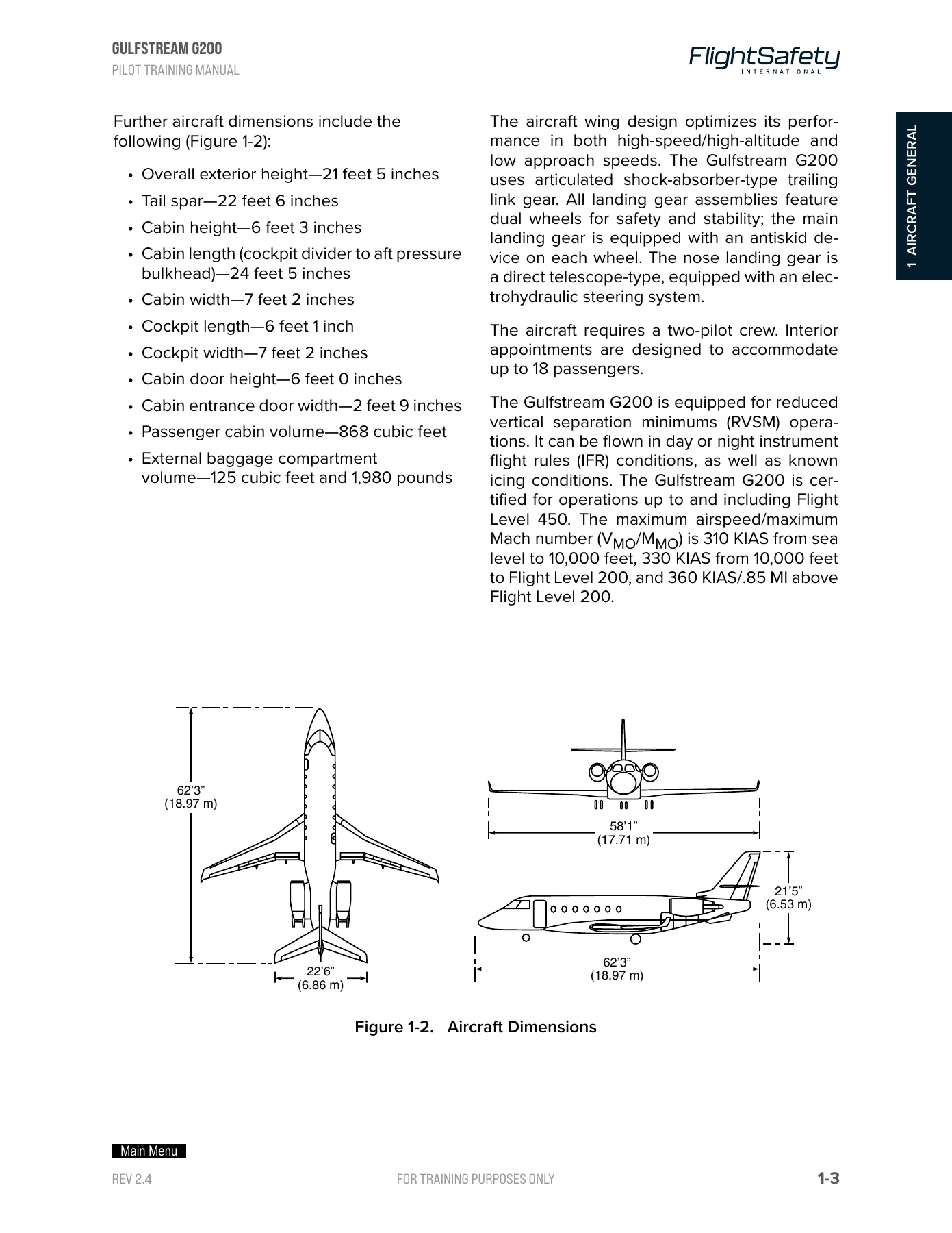
Figure 1-2. Aircraft Dimensionsp. 11
Figure 1-3. Airplane Structure and Sectionsp. 12
Figure 1-4. Nose Structurep. 13
Figure 1-5. Wing Structurep. 14
Figure 1-6. Interior Arrangementp. 15
Figure 1-7. Cabin Doorp. 16
Figure 1-8. Baggage Compartmentp. 17
Figure 1-9. Fuel Systemp. 19
Figure 1-10. Danger Zonep. 20
Figure 1-11. Deicer Bootsp. 21
Figure 1-12. Hydraulic Systemp. 23
Figure 1-13. Steeringp. 24
Figure 1-14. Secondary Flight Controlsp. 26
Figure 1-15. Krueger Flapp. 26
Figure 1-16. Avionicsp. 27
2 ELECTRICAL POWER SYSTEMSp. 31
Contentsp. 31
Introductionp. 33
GENERALp. 33
DC POWER SYSTEMp. 34
System Descriptionp. 34
Component Descriptionp. 35
Controls and Indicationsp. 38
System Operationp. 46
AC POWER SYSTEMp. 50
System Descriptionp. 50
LIMITATIONSp. 51
QUESTIONSp. 52
Illustrationsp. 32
Figure 2-1. Basic DC Schematicp. 34
Figure 2-2. Overhead Panel Electrical Power Controlsp. 39
Figure 2-3. DC Electrical Switches Schematicp. 40
Figure 2-4. Electrical Power System Circuit Breakersp. 42
Figure 2-5. Electrical Power EICAS Warning and Caution Messagesp. 43
Figure 2-6. EICAS Electrical Pagep. 45
Figure 2-7. DC Electrical System during Normal Operationp. 47
Figure 2-8. DC External Powerp. 51
3 LIGHTINGp. 55
Contentsp. 55
Introductionp. 57
GENERALp. 57
SYSTEM DESCRIPTIONp. 57
COMPONENT DESCRIPTIONp. 58
Interior Lightsp. 58
Exterior Lightsp. 61
Emergency Lightsp. 63
CONTROLS AND INDICATIONSp. 65
Interior Lightsp. 65
Exterior Lightsp. 69
Emergency Lightsp. 71
QUESTIONSp. 72
Illustrationsp. 56
Figure 3-1. Exterior Lightingp. 60
Figure 3-2. Exterior Emergency Lightsp. 62
Figure 3-3. Cockpit Light Controls and Circuit Breakersp. 64
Figure 3-4. Cabin Light Controls and Circuit Breakersp. 67
Figure 3-5. Exterior Light Controls and Circuit Breakersp. 68
Figure 3-6. Emergency Light Controls and Circuit Breakersp. 70
Tablesp. 56
Table 3-1. INTERIOR LIGHTSp. 58
4 MASTER WARNING SYSTEMp. 75
Contentsp. 75
Introductionp. 77
GENERALp. 77
SYSTEM DESCRIPTIONp. 78
COMPONENT DESCRIPTIONp. 79
EICAS Displayp. 79
Multifunction Displaysp. 79
EICAS Display Controlsp. 79
Display Control Panelp. 79
Reversionary Switching Panelp. 79
CONTROLS AND INDICATIONSp. 81
EICAS Display Controlsp. 81
Reversionary Switching Panelp. 81
EICAS Displayp. 83
SYSTEM OPERATIONp. 96
QUESTIONSp. 97
Illustrationsp. 76
Figure 4-1. EICAS Block Diagramp. 78
Figure 4-2. EICAS Controls and Displaysp. 80
Figure 4-3. EICAS Display Control Panelp. 81
Figure 4-4. Reversionary Switching Panelp. 82
Figure 4-5. EICAS Basic Primary Displayp. 83
Figure 4-6. EICAS Primary Pageβ€”Engine Start Modep. 85
Figure 4-7. EICAS Extended CAS Primary Pagep. 86
Figure 4-8. EICAS Cruise Primary Pagep. 87
Figure 4-9. EICAS Secondary Pagep. 88
Figure 4-10. EICAS Electrical Pagep. 89
5 FUEL SYSTEMp. 99
Contentsp. 99
Introductionp. 103
GENERALp. 103
FUEL STORAGE SYSTEMp. 105
System Descriptionp. 105
Component Descriptionp. 108
FUEL DISTRIBUTION SYSTEMp. 114
System Descriptionp. 114
Refueling and Defuelingp. 120
Component Descriptionp. 123
Controls and Indicationsp. 126
System Operationp. 131
FUEL QUANTITY SYSTEMp. 136
System Descriptionp. 136
Component Descriptionp. 140
QUESTIONSp. 142
Illustrationsp. 100
Figure 5-1. Fuel Systemp. 104
Figure 5-2. Fuel Storage Systemp. 105
Figure 5-3. Center and Feed Tanks Schematicp. 109
Figure 5-4. Left Wing Tankp. 110
Figure 5-5. Center Tankβ€”Side Viewp. 111
Figure 5-6. Forward Tankp. 112
Figure 5-7. Fuselage Tankp. 113
Figure 5-8. Vent Linesp. 115
Figure 5-9. Engine and APU Feed Systemp. 116
Figure 5-10. Fuel Transfer Systemp. 118
Figure 5-11. Fuel Jettison Systemp. 119
Figure 5-12. Refueling Systemβ€”Top Viewp. 121
Figure 5-13. Refueling Systemβ€”Front Viewp. 121
Figure 5-14. Defueling Systemp. 122
Figure 5-15. Refuel and Defuel Control Panel and Refueling Portp. 123
Figure 5-16. Defueling Portp. 124
Figure 5-17. Center Instrument Panelp. 126
Figure 5-18. Overhead Panelp. 127
Figure 5-19. Pedestal Controlsp. 129
Figure 5-20. Exterior Fueling Panelp. 129
Figure 5-21. EICAS Messagesp. 131
Figure 5-22. Fuel Transfer Sequence (Sheet 1 of 2)p. 133
Figure 5-23. Fuselage, Forward, Center and Feed Tank Probesp. 137
Figure 5-24. EICAS Primary and Secondary Page Displaysp. 138
Figure 5-25. Tank Probesp. 140
Tablesp. 101
Table 5-1. FUEL TANK CAPACITIESp. 106
Table 5-2. AUTHORIZED TYPES OF FUELp. 107
6 AUXILIARY POWER UNITp. 145
Contentsp. 145
Introductionp. 147
GENERALp. 147
SYSTEM DESCRIPTIONp. 149
Powerplantp. 149
Electronic Control Unitp. 149
Air Inletp. 150
Exhaust Systemp. 150
Fuel Control Systemp. 150
COMPONENT DESCRIPTIONp. 150
Load Control Valvep. 150
Surge Control Valvep. 150
Air Inlet Doorp. 150
Fuel Shutoff Valvep. 151
Fuel Control Unitp. 151
Oil and Lubrication Systemp. 152
Fire Warning and Extinguishing Systemp. 152
CONTROLS AND INDICATIONSp. 152
Overhead Panelp. 152
ECS Selectorp. 154
APU Maintenance Controlsp. 154
EICAS Messagesp. 154
SYSTEM OPERATIONp. 157
Startingp. 157
Normal Shutdownp. 157
Automatic Shutdownp. 158
LIMITATIONSp. 159
QUESTIONSp. 160
Illustrationsp. 146
Figure 6-1. Installed APUβ€”Left Side Viewp. 148
Figure 6-2. Installed APUβ€”Top Viewp. 149
Figure 6-3. APU Controls and Indicatorsp. 153
Figure 6-4. Maintenance Panel APU Controlsp. 155
Figure 6-5. APU Messagesβ€”EICASp. 156
Figure 6-6. APU Starting Schedulep. 158
Figure 6-7. APU In-flight Load Limitsp. 159
7 POWERPLANTp. 161
Contentsp. 161
Introductionp. 165
GENERALp. 165
ENGINE DESCRIPTIONp. 166
MAJOR SECTIONSp. 166
Generalp. 166
Intake Fanp. 166
Compressorp. 168
Combustionp. 169
Turbinep. 169
Exhaustp. 169
Accessory Gearboxp. 169
ENGINE SYSTEMSp. 169
Oil Systemp. 169
Fuel Systemp. 172
Thrust Management Systemp. 177
Auto throttle system (ATS)p. 181
ENGINE OPERATIONp. 184
Electronic Engine Controlp. 184
Engine Startingp. 184
Engine Idlep. 185
Forward Thrustp. 186
Engine Synchronizationp. 186
Automatic Power Reservep. 187
Engine Shutdownp. 188
Thrust Reverser Operationp. 188
CONTROLS AND INDICATIONSp. 192
Center Instrument Panelp. 192
Pedestal Controlsp. 192
Overhead Control Panelp. 194
Circuit Breaker Panelp. 196
EICAS Messagesp. 196
LIMITATIONSp. 200
QUESTIONSp. 202
Illustrationsp. 163
Figure 7-1. Components and Accessoriesp. 167
Figure 7-2. Major Sectionsp. 168
Figure 7-3. Engine Oil Systemp. 170
Figure 7-4. Oil System Indicationsp. 171
Figure 7-5. Fuel Distribution Systemp. 172
Figure 7-6. Hydromechanical Metering Unit Schematicp. 174
Figure 7-7. Hydromechanical Metering Unit and Fuel Pumpp. 175
Figure 7-8. Fuel Componentsp. 176
Figure 7-9. Mechanical Fuel Shutoff Valvep. 177
Figure 7-10. Ignition Componentsp. 178
Figure 7-11. Thrust Reverser System Schematicp. 179
Figure 7-12. Exhaust Componentsp. 180
Figure 7-13. Auto Throttle System Schedulep. 182
Figure 7-14. Idle N2/PALT Schedulep. 185
Figure 7-15. N1/TLA Schedulep. 186
Figure 7-16. PW306A Performance Ratingp. 187
Figure 7-17. Thrust Reverser Operationp. 189
Figure 7-18. Thrust Reverser Hydraulic System Operationp. 191
Figure 7-19. Center Instrument Panelp. 192
Figure 7-20. ENG DATA REC Switchesp. 192
Figure 7-21. Thrust Lever Quadrant Controlsp. 193
Figure 7-22. Overhead Panelp. 195
Figure 7-23. EICAS Messagesp. 197
Figure 7-24. Engine Vibration Indication Systemp. 199
Figure 7-25. Engine Vibration Testp. 200
Tablesp. 164
Table 7-1. FUEL PUMP CAPACITYp. 173
Table 7-2. MSD Examplesp. 181
Table 7-3. ATS DISPLAYS AND INDICATIONSp. 183
Table 7-4. ENGINE INSTRUMENT MARKINGSp. 201
8 FIRE PROTECTIONp. 205
Contentsp. 205
Introductionp. 207
GENERALp. 207
SYSTEM DESCRIPTIONp. 209
Engine Fire/Overheat Protectionp. 209
APU Compartment Detectionp. 211
Baggage Compartmentp. 211
Engine Fire Control Modulep. 213
Fire Extinguishingp. 215
COMPONENT DESCRIPTIONp. 215
Fire/Overheat Detectorsp. 215
Fire-Extinguisher Bottlesp. 215
Thermal Relief Valve and Discharge Indicatorp. 216
Portable Fire Extinguishersp. 217
CONTROLS AND INDICATIONSp. 217
Center Instrument Panel Controlsp. 217
Overhead Panel Controlsp. 219
Pedestal Controlsp. 222
Maintenance Panel Controlsp. 222
EICAS Messagesp. 222
SYSTEM OPERATIONp. 224
Normal Operationp. 224
System Faults and Testingp. 224
QUESTIONSp. 226
Illustrationsp. 206
Figure 8-1. Fire Protection Systemp. 208
Figure 8-2. Engine Fire Zonesp. 210
Figure 8-3. APU Compartment Protectionp. 211
Figure 8-4. Baggage Compartment Protectionp. 212
Figure 8-5. Fire Detector Responderp. 213
Figure 8-6. Fire-Extinguishing Bottles and Check Valvep. 214
Figure 8-7. Engine and APU Fire Detectorp. 215
Figure 8-8. Fire-Extinguishing Bottlesp. 216
Figure 8-9. Portable Fire Extinguisherp. 217
Figure 8-10. Fire and Overheat Annunciationsp. 218
Figure 8-11. PRESS TO TEST Switchlightp. 219
Figure 8-12. IND TEST Switchp. 220
Figure 8-13. Overhead Panel Controlsp. 221
Figure 8-14. BAGG PRESS Switchlightp. 221
Figure 8-15. Maintenance Panel APU Fire Controlsp. 223
Figure 8-16. System Fault and Indicationsp. 225
9 PNEUMATICSp. 229
Contentsp. 229
Introductionp. 231
GENERALp. 231
BLEED-AIR SYSTEMp. 232
System Descriptionp. 232
Component Descriptionp. 232
Pneumatic Subsystemsp. 236
Bleed-Air Leak Detectionp. 238
Controls and Indicationsp. 239
System Operationp. 240
RAM-AIR SYSTEMp. 241
System Descriptionp. 241
Component Descriptionp. 242
Controls and Indicationsp. 242
QUESTIONSp. 243
Illustrationsp. 230
Figure 9-1. Pneumatic (Bleed) System Componentsp. 233
Figure 9-2. Bleed-Air Precooler and Overtemperature/Overpressure Switchesp. 234
Figure 9-3. Pneumatic Subsystemsp. 237
Figure 9-4. Bleed-Air Leak Detection Systemp. 238
Figure 9-5. Bleed-Air Controlp. 239
Figure 9-6. EICAS Bleed-Air Messagesp. 240
Figure 9-7. Ram Air Systemp. 241
10 ICE AND RAIN PROTECTIONp. 245
Contentsp. 245
Introductionp. 247
GENERALp. 247
ICE AND RAIN SUBSYSTEMSp. 249
System Descriptionp. 249
Component Descriptionp. 249
Controls and Indicationsp. 250
PNEUMATIC BOOTSp. 250
System Descriptionp. 250
Component Descriptionp. 251
Controls and Indicationsp. 253
System Operationp. 253
WINDSHIELD HEATING AND RAIN REMOVAL SYSTEMp. 255
System Descriptionp. 255
Component Descriptionp. 255
Controls and Indicationsp. 256
System Operationp. 257
PROBE HEATINGp. 257
System Descriptionp. 257
Component Descriptionp. 257
Controls and Indicationsp. 259
System Operationp. 260
ICE DETECTIONp. 260
System Descriptionp. 260
Component Descriptionp. 260
Controls and Indicationsp. 261
System Operationp. 261
Baggage Compartment Heatingp. 261
QUESTIONSp. 262
Illustrationsp. 246
Figure 10-1. Ice and Rain Protected Areasp. 248
Figure 10-2. Inlet Anti-icingp. 249
Figure 10-3. Probe and Nacelle Switchesp. 250
Figure 10-4. Pneumatic Bootsp. 251
Figure 10-5. Pneumatic Boots System Schematicp. 252
Figure 10-6. Ejector Flow Control Valvep. 252
Figure 10-7. Deicing Controls on the Overhead Panelp. 254
Figure 10-8. Windshield Heating Elementsp. 255
Figure 10-9. Windshield Heat Controlsp. 256
Figure 10-10. Probe Heating Schematicp. 258
Figure 10-11. Probe Heat Switchp. 259
Figure 10-12. Ice Detectorp. 260
11 AIR CONDITIONINGp. 265
Contentsp. 265
Introductionp. 267
GENERALp. 267
ENVIRONMENTAL CONTROL UNITp. 268
System Descriptionp. 268
Component Descriptionp. 268
TEMPERATURE CONTROLp. 272
System Descriptionp. 272
Component Descriptionp. 273
DISTRIBUTIONp. 274
System Descriptionp. 274
Component Descriptionp. 274
CONTROLS AND INDICATIONSp. 277
ECS Panelp. 277
Overhead Panelp. 277
Circuit-Breaker Panelp. 277
EICAS Indicationsp. 279
SYSTEM OPERATIONp. 279
QUESTIONSp. 281
Illustrationsp. 266
Figure 11-1. Environmental Control Unitp. 269
Figure 11-2. Environmental Control System Schematicp. 270
Figure 11-3. Temperature Control Section Diagramp. 273
Figure 11-4. Air-Conditioning Systemp. 275
Figure 11-5. Air-Conditioning Systemp. 276
Figure 11-6. Air-Conditioning Controls and Indicationsp. 278
Figure 11-7. Air-Conditioning EICAS Datap. 280
12 PRESSURIZATIONp. 283
Contentsp. 283
Introductionp. 285
GENERALp. 285
SYSTEM DESCRIPTIONp. 287
Cabin Pressure Control Systemβ€”Automatic Modep. 287
Manual Pressurization Modep. 288
Baggage Compartment Pressurizationp. 288
COMPONENT DESCRIPTIONp. 288
Outflow Valvep. 289
Cabin Pressure Controllerp. 289
Safety Relief Valvep. 290
CONTROLS AND INDICATIONSp. 290
CABIN PRESS Panelp. 290
ECS Panelp. 291
Pressurization Circuit Breakersp. 293
EICAS Messagesp. 294
SYSTEM OPERATIONp. 295
Ground Modep. 295
Takeoff Modep. 295
Climb Modep. 295
Cruise Modep. 296
Descent Modep. 296
Landing Modep. 296
Takeoff Abortp. 297
Touch and Gop. 297
Manual Modep. 297
QUESTIONSp. 298
Illustrationsp. 284
Figure 12-1. Cabin Pressure Control Systemp. 286
Figure 12-2. Typical Flight Profilep. 287
Figure 12-3. Outflow Valve Schematicp. 289
Figure 12-4. Cabin Pressure Control Panelp. 291
Figure 12-5. Pressurization Controls and Indicationsp. 292
Figure 12-6. EICAS Messages and Indicationsp. 294
Figure 12-7. Typical Takeoff Profilep. 296
Figure 12-8. Typical Descent Profilep. 297
13 HYDRAULIC POWER SYSTEMp. 299
Contentsp. 299
Introductionp. 301
GENERALp. 301
SYSTEM DESCRIPTIONp. 303
Right Hydraulic Systemp. 303
Left Hydraulic Systemp. 303
COMPONENT DESCRIPTIONp. 306
Hydraulic Reservoirsp. 306
Engine-Driven Pumpsp. 307
Hydraulic Pressure and Return Filtersp. 307
Air-Pressure Regulatorp. 307
Manifold Assemblyp. 308
Auxiliary Hydraulic Pumpp. 309
CONTROLS AND INDICATIONSp. 309
Left and Right FIRE/OVERHT Switchlightsp. 309
AUX HYD PUMP Switchp. 311
EICAS Messagesp. 311
SYSTEM OPERATIONp. 312
QUESTIONSp. 313
Illustrationsp. 300
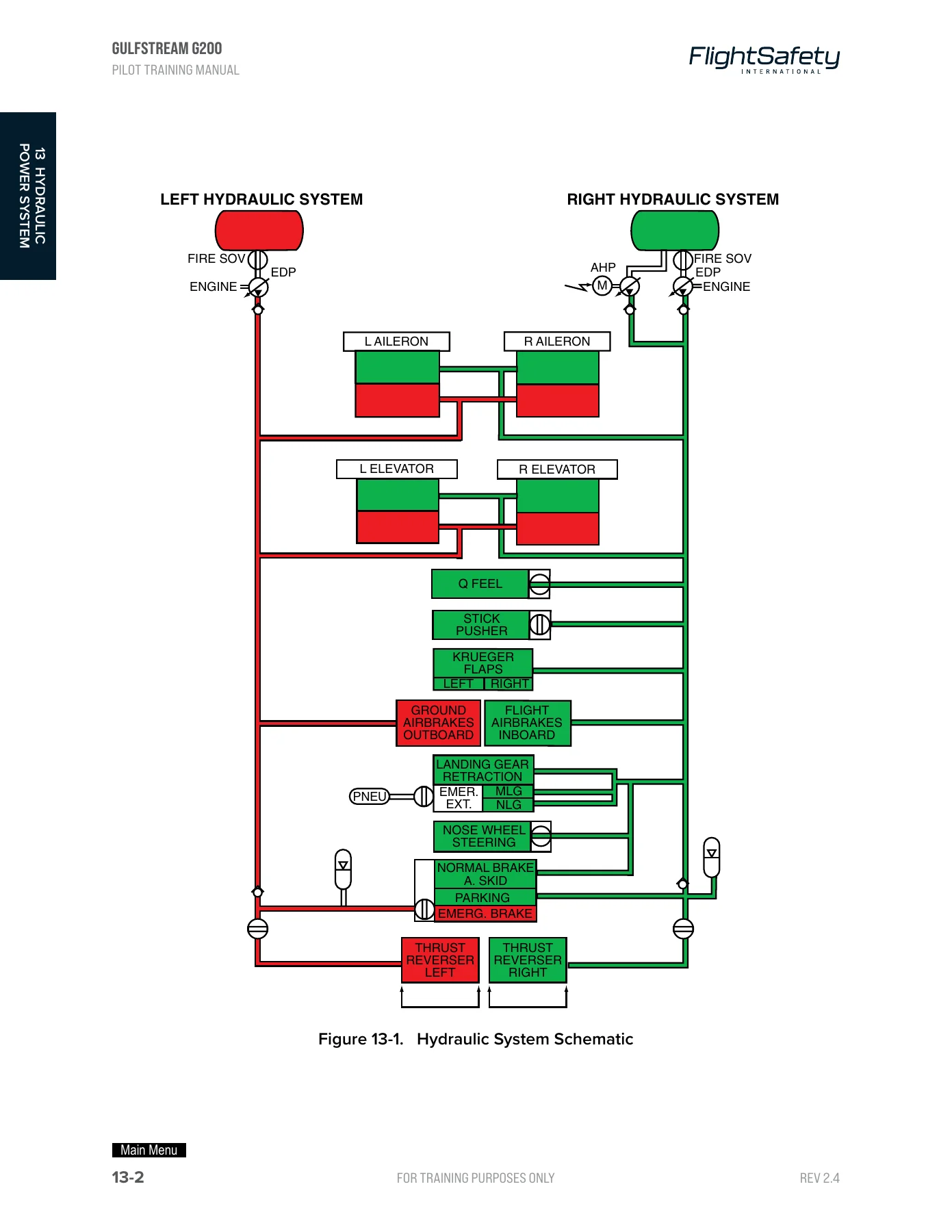
Figure 13-1. Hydraulic System Schematicp. 302
Figure 13-2. Right Hydraulic System Locationp. 304
Figure 13-3. Left Hydraulic System Locationp. 305
Figure 13-4. Hydraulic Reservoirp. 306
Figure 13-5. Engine-Driven Pumpp. 307
Figure 13-6. Air-Pressure Regulatorp. 308
Figure 13-7. Manifold Assemblyp. 308
Figure 13-8. Auxiliary Hydraulic Pumpp. 309
Figure 13-9. Figure 13-9. Hydraulic System Controlsp. 310
14 LANDING GEAR AND BRAKESp. 315
Contentsp. 315
Introductionp. 319
GENERALp. 319
MAIN LANDING GEAR SYSTEMp. 320
System Descriptionp. 320
Component Descriptionp. 320
NOSE LANDING GEAR SYSTEMp. 324
System Descriptionp. 324
Component Descriptionp. 324
Controls and Indicationsp. 327
LANDING GEAR EXTENSION AND RETRACTIONp. 328
System Descriptionp. 328
Controls and Indicationsp. 328
System Operationp. 330
EMERGENCY LANDING GEAR EXTENSIONp. 330
System Descriptionp. 330
Component Descriptionp. 330
Controls and Indicatorsp. 331
System Operationp. 332
WHEEL AND BRAKE SYSTEMp. 332
System Descriptionp. 332
Component Descriptionp. 333
Controls and Indicationsp. 336
System Operationp. 336
NOSEWHEEL STEERING SYSTEMp. 339
System Descriptionp. 339
Component Descriptionp. 340
Controls and Indicationsp. 341
System Operationp. 341
QUESTIONSp. 343
Illustrationsp. 317
Figure 14-1. Main Landing Gear Assemblyp. 321
Figure 14-2. Main Landing Gear Support Strutp. 322
Figure 14-3. Forward and Aft Uplocksp. 323
Figure 14-4. Nose Landing Gear Assemblyp. 324
Figure 14-5. Nose Landing Gear Shock Strut Assemblyp. 325
Figure 14-6. Nose Landing Gear Brace Assemblyp. 326
Figure 14-7. EICAS Landing Gear Position Indicationsp. 329
Figure 14-8. Emergency Gear Selector Valvep. 330
Figure 14-9. Emergency Gear Down Handlep. 331
Figure 14-10. Landing Gear Control Lever Assemblyp. 332
Figure 14-11. Brake Systemp. 333
Figure 14-12. Brake Assemblyp. 334
Figure 14-13. Parking Brake Control and Indicationsp. 337
Figure 14-14. Steering Actuators and Mechanismp. 340
Figure 14-15. Nosewheel Steering Handwheelp. 341
15 FLIGHT CONTROLSp. 345
Contentsp. 345
Introductionp. 349
GENERALp. 349
AILERON SYSTEMp. 350
System Descriptionp. 350
Component Descriptionp. 351
Controls and Indicationsp. 354
RUDDER SYSTEMp. 356
System Descriptionp. 356
Component Descriptionp. 356
Controls and Indicationsp. 359
ELEVATOR SYSTEMp. 363
System Descriptionp. 363
Component Descriptionp. 364
STALL PROTECTION AND Q-FEEL SYSTEMp. 368
Controls and Indicationsp. 374
HORIZONTAL STABILIZER TRIM SYSTEMp. 375
System Descriptionp. 375
Component Descriptionp. 376
Controls and Indicationsp. 376
System Operationp. 380
FLAPS/SLATS SYSTEMp. 382
System Descriptionp. 382
Component Descriptionp. 382
Controls and Indicationsp. 390
System Operationp. 392
AIRBRAKESp. 396
System Descriptionp. 396
Component Descriptionp. 397
Controls and Indicationsp. 398
System Operationp. 400
QUESTIONSp. 401
Illustrationsp. 347
Figure 15-1. Flight Control System Overviewp. 350
Figure 15-2. Aileron Control Systemp. 351
Figure 15-3. Aileron Servoactuator Locationp. 352
Figure 15-4. Aileron Servoactuatorp. 353
Figure 15-5. Aileron Controls and Indicationsp. 355
Figure 15-6. Control Columnp. 356
Figure 15-7. Aileron EICAS Displaysp. 357
Figure 15-8. Rudder System Overviewp. 357
Figure 15-9. Rudder and Rudder Trim Systemp. 358
Figure 15-10. Rudder Bias Systemp. 359
Figure 15-11. Rudder System Controlsp. 360
Figure 15-12. Rudder Pedal Assemblyp. 361
Figure 15-14. Gust Lock Handlep. 362
Figure 15-13. Rudder Gust Lock Assemblyp. 362
Figure 15-15. Rudder Trim Switchp. 362
Figure 15-16. Rudder EICAS Displayp. 363
Figure 15-17. Elevator System Overviewp. 364
Figure 15-18. Elevator Systemp. 365
Figure 15-19. Elevator Servoactuatorp. 366
Figure 15-20. Cable Tension Regulator and Artificial Feel Spring Assemblyp. 367
Figure 15-21. Angle of Attack Sensorsp. 369
Figure 15-22. Stick Shakerp. 370
Figure 15-23. Approach Indexersp. 371
Figure 15-24. Stall Speed Indicationsp. 371
Figure 15-25. Stall Protection and Q-Feel System Controlsp. 373
Figure 15-26. Elevator Controls and Indicationsp. 374
Figure 15-27. Elevator EICAS Messagesp. 375
Figure 15-28. Horizontal Stabilizer Trim Overviewp. 377
Figure 15-29. Horizontal Stabilizer Trim Controls and Indicationsp. 379
Figure 15-30. Horizontal Stabilizer Trim EICAS Displaysp. 380
Figure 15-31. Override Controlsp. 381
Figure 15-32. Flaps System Overviewp. 383
Figure 15-33. Flap Power Drive Unitp. 384
Figure 15-34. Ballscrew Actuatorsp. 385
Figure 15-35. Flexible Shaftsp. 386
Figure 15-36. Krueger Flapp. 387
Figure 15-37. Slatp. 388
Figure 15-38. Slat Actuators and Flexible Shaftsp. 389
Figure 15-39. Flaps/Slats Controls and Indicationsp. 391
Figure 15-40. EICAS Primary Display Pagep. 393
Figure 15-41. Flaps/Slats System Operationp. 395
Figure 15-42. Airbrakesp. 396
Figure 15-43. Airbrake Selector Valvep. 397
Figure 15-44. Airbrake Controlsp. 398
Figure 15-45. EICAS Airbrake Messagesp. 399
16 AVIONICSp. 403
Contentsp. 403
Introductionp. 405
GENERALp. 405
COMMUNICATION SYSTEMp. 406
System Descriptionp. 406
Component Descriptionp. 406
Controls and Indicationsp. 407
System Operationp. 409
NAVIGATION SYSTEMSp. 409
Flight Environment Data Sectionp. 409
Attitude and Direction Sectionp. 413
Standby Instrument Sectionp. 415
Radio Altimeter and Weather Radar Sectionp. 417
Electronic Navigation Sectionp. 420
Flight Management Systemp. 423
Electronic Flight Instrument Systemp. 425
AUTOPILOTp. 432
System Descriptionp. 432
Component Descriptionp. 433
Controls and Indicationsp. 433
PASSENGER ADDRESS AND ENTERTAINMENT SYSTEMp. 439
System Descriptionp. 439
Component Descriptionp. 439
Controls and Indicationsp. 439
AIRBORNE RADIO TELEPHONE SYSTEMp. 440
System Descriptionp. 440
Component Descriptionp. 440
CABIN DISPLAY SYSTEMp. 440
System Descriptionp. 440
QUESTIONSp. 441
Illustrationsp. 404
Figure 16-1. Audio Control Panelp. 408
Figure 16-2. Radio Tuning Unitp. 408
Figure 16-3. Pitot-Static Air Pressure Schematicp. 410
Figure 16-4. Pitot Probep. 411
Figure 16-5. Static Portp. 411
Figure 16-6. Air Data Reference Panelp. 412
Figure 16-7. Compass Control Unitp. 414
Figure 16-8. Standby Airspeed Indicatorp. 415
Figure 16-9. Standby Altimeterp. 415
Figure 16-10. Standby Attitude Indicatorp. 416
Figure 16-11. Air Data Reference Panelp. 417
Figure 16-12. Weather Radar Control Panelp. 418
Figure 16-13. Radio Tuning Unitp. 420
Figure 16-14. Control Display Unitp. 423
Figure 16-15. Primary Flight Displayp. 426
Figure 16-16. Multifunction Displayp. 427
Figure 16-17. Display Control Panelp. 431
Figure 16-18. Reversionary Switch Panelp. 432
Figure 16-19. Control Wheel Switchesp. 434
Figure 16-20. Flight Control Panel (Sheet 1 of 2)p. 434
17 MISCELLANEOUS SYSTEMSp. 443
Contentsp. 443
Introductionp. 445
GENERALp. 445
OXYGEN SYSTEMp. 446
System Descriptionp. 446
Component Descriptionp. 449
System Operationp. 451
Controls and Indicationsp. 451
Passenger Oxygen Systemp. 457
WATER/WASTE SYSTEMp. 461
System Descriptionp. 461
Component Descriptionp. 461
System Operationp. 461
COCKPIT VOICE RECORDERp. 462
System Descriptionp. 462
Component Descriptionp. 462
Controls and Indicationsp. 462
System Operationp. 463
EMERGENCY LOCATOR TRANSMITTERp. 463
System Descriptionp. 463
Component Descriptionp. 463
Controls and Indicationsp. 463
CLOCKp. 464
System Descriptionp. 464
Component Descriptionp. 464
Controls and Indicationsp. 465
QUESTIONSp. 466
Illustrationsp. 444
Figure 17-1. Oxygen System Schematicp. 447
Figure 17-2. Executive Configurationp. 448
Figure 17-3. Commuter Configurationp. 448
Figure 17-4. Oxygen Masksp. 449
Figure 17-5. Oxygen Supply Componentsp. 450
Figure 17-6. Standard and Optional Oxygen Cylindersp. 451
Figure 17-7. Crew Mask and Stowage Boxp. 452
Figure 17-8. Crew Mask Controls and Regulatorp. 453
Figure 17-9. Oxygen System Controlsp. 454
Figure 17-10. PASSENGER OXYGEN Control Panelβ€”Mod 20195p. 455
Figure 17-11. EICAS Secondary Page Displayp. 456
Figure 17-12. Passenger Dropout Boxp. 459
Figure 17-13. Therapeutic Oxygen System and Maskp. 460
Figure 17-14. Digital Clockp. 464
CREW RESOURCE MANAGEMENTp. 467
Contentsp. 467
INTRODUCTIONp. 469
CREW CONCEPT BRIEFING GUIDEp. 469
Common Termsp. 469
Pretakeoff Briefing (IFR/VFR)p. 472
Crew Coordination during the Approach Sequencep. 473
CALLOUTSp. 474
Enroute Climb/Descentp. 474
Approachβ€”Precisionp. 474
Approachβ€”NONPrecisionp. 475
Missed Approachp. 475
Significant Deviation Calloutsp. 476
Illustrationsp. 468
Figure CRM-1. Situational Awareness in the Cockpitp. 470
Figure CRM-2. Communication Processp. 471
Figure CRM-3. Decision-Making Processp. 471
Figure CRM-4. Command and Leadershipp. 472
APPENDIX ANSWERS TO QUESTIONSp. 477


IMAGES PREVIEW

Gulfstream G200 Pilot Training Manual - Aircraft Systems Volume 2 Second Edition PDF β€” PDF page 1 preview
Gulfstream G200 Pilot Training Manual - Aircraft Systems Volume 2 Second Edition PDF β€” PDF page 11 preview
Gulfstream G200 Pilot Training Manual - Aircraft Systems Volume 2 Second Edition PDF β€” PDF page 302 preview

Instant PDF Delivery

This Gulfstream G200 Pilot Training Manual is delivered as an instant-download PDF. There is no shipping, no waiting, and no physical media to keep track of. Once your order is complete, you can download the file and read it on a laptop, tablet, or phone, or print the pages you need for study or reference. It is a practical, portable way to keep the complete Volume 2 aircraft systems training manual on hand wherever you study or work on the G200.
Reviews

There are no reviews yet.

Be the first to review “Gulfstream G200 Pilot Training Manual – Aircraft Systems Volume 2 Second Edition PDF”

What Our Customers Say

β˜…β˜…β˜…β˜…β˜… Live reviews from customers
Loading customer reviews...
0
    0
    Your Cart
    Your cart is emptyReturn to Shop
    πŸ›’
    Recently Purchased
    πŸ•’ verified order