
Airbus A319 A320 A321 Illustrated Parts Catalog Chapter 73 Engine Fuel and Control PDF
Original price was: $34.95.$19.95Current price is: $19.95.
Airbus A319/A320/A321 Illustrated Parts Catalog for Chapter 73 — Engine Fuel & Control. Covers CFM56/Z400 engines with exploded views, part numbers, nomenclature, and effective page listings across 676 pages.
Description
Airbus A319 A320 A321 Illustrated Parts Catalog — Chapter 73
This Airbus A319 A320 A321 Illustrated Parts Catalog Chapter 73 Engine Fuel and Control PDF is a complete, diagram-rich parts reference for the fuel and control systems on the A319, A320, and A321 family. Every figure in this chapter is built around exploded illustrations tied directly to part-number tables, so you can identify, cross-reference, and order the correct component for fuel drain, fuel supply, fuel nozzle, cooling air, hydromechanical control, electronic control, sensing, and indicating systems.
File Details
- Manual type: Illustrated Parts Catalog (IPC)
- Brand: Airbus
- Models covered: A319, A320, A321
- Chapter: 73 — ENG. FUEL & CONTROL
- Engines referenced: CFM56, Z400; V2500 sections where applicable
- Language: English
- File format: PDF
- Page count: 676
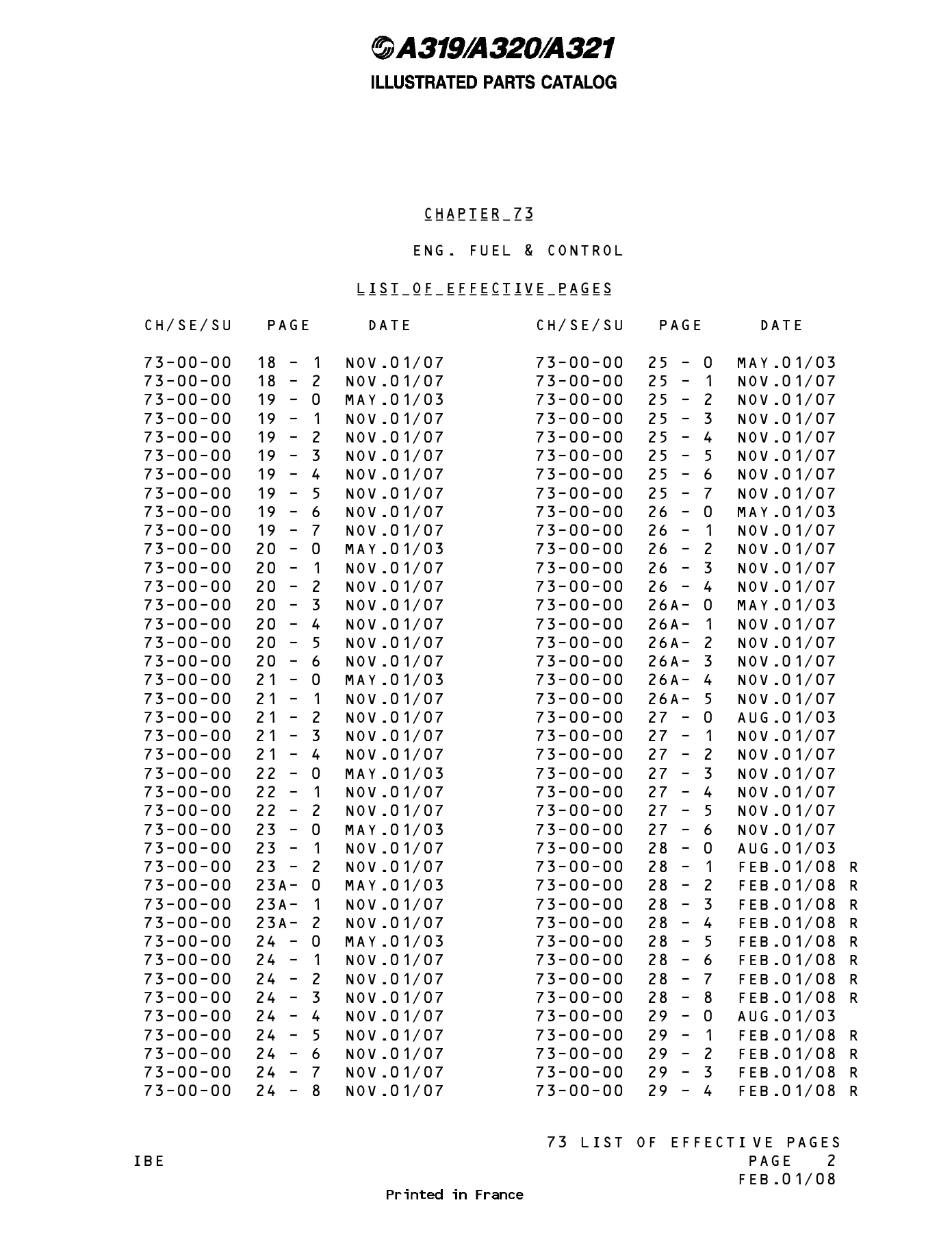
- Document date visible: FEB.01/08 (latest revision pages), MAY.01/03, AUG.01/03, NOV.01/05, MAY.01/06, AUG.01/06, FEB.01/07, NOV.01/07
- Origin: Printed in France
Chapters Covered
Chapter 73 is split into figure-driven sub-sections. Every section below is present in this PDF with its own exploded illustrations and parts data:
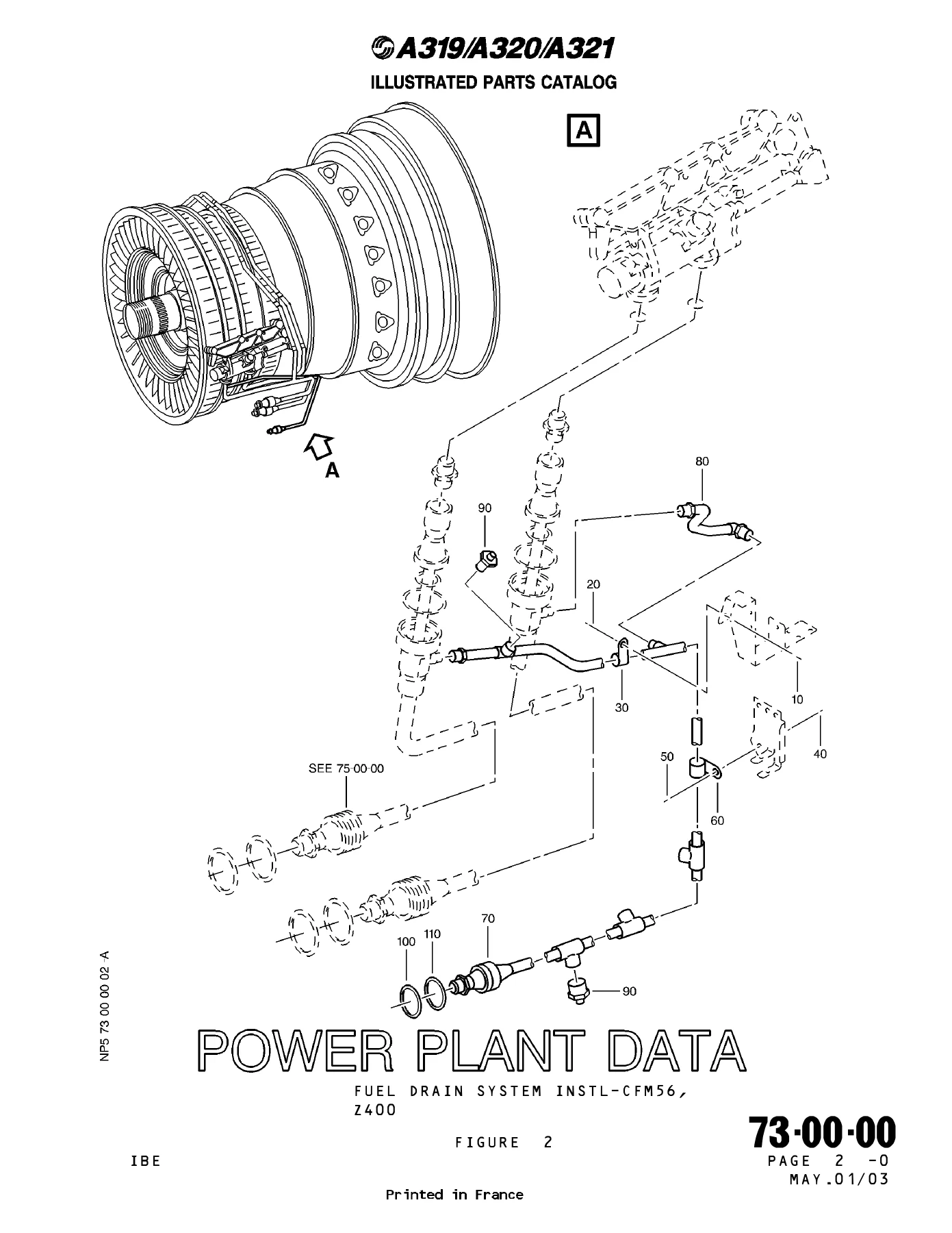
- 73-00-00 — Fuel Drain System Instl — CFM56, Z400 (Figures 2, 2A, 3, 4, 4A, 6, 8, 9, 10, 11, 12, 13)
- 73-11-11 — Hose Instl — Main Fuel Supply, CFM56, Z400 (Figures 1, 1A)
- 73-11-20 — Servo Fuel Heater Instl — CFM56, Z400 (Figures 1, 1A)
- 73-11-31 — Gasket Seal — Fuel Manifold Instl — CFM56, Z400 (Figures 1, 1A)
- 73-11-40 — Fuel Nozzle Instl — CFM56, Z400 (Figures 1, 2, 3, 3A, 4, 4A, 4B, 4C, 5, 5A, 5B, 5C, 6, 6A, 6B, 6C, 7, 7A, 7B, 7C, 8, 8A, 8B, 8C, 9, 9A, 10, 10A)
- 73-11-40 — Cooling Air — Right Side Instl — CFM56, Z400 (Figures 15, 15A, 16, 17)
- 73-11-40 — Cooling Air — Left Side Instl — CFM56, Z400 (Figures 18, 18A, 18B, 18C, 18D, 18E, 19, 19A, 19B)
- 73-11-45 — Filter Instl — Fuel Nozzle, CFM56, Z400 (Figures 1, 1A)
- 73-11-48 — Fuel Return Valve Hose Instl — CFM56, Z400 (Figures 1, 1A)
- 73-11-49 — Fuel Tubes Instl — CFM56, Z400 (Figures 1, 1A, 2, 2A)
- 73-11-50 — Return Valve Instl — Fuel, CFM56, Z400 (Figures 1, 1A)
- 73-11-60 — IDG Oil Cooler Instl — CFM56, Z400 (Figures 1, 1A)
- 73-11-70 — Burner Staging Valve Instl — CFM56, Z400 (Figures 1, 1A, 1B, 2, 2A, 3)
- 73-21-10 — Hydromechanical Unit Instl — CFM56, Z400 (Figures 1, 1A, 1B)
- 73-21-20 — Sensor Instl — T25 Temperature, Z430-440 (Figure 1)
- 73-21-30 — Alternator Instl — Control, CFM56, Z400 (Figures 1, 1A)
- 73-21-40 — Sensor Instl — T12 Temperature, CFM56, Z400 (Figures 1, 1A, 1B)
- 73-21-60 — Electronic Control Unit Instl — CFM56, Z400 (Figures 1, 1A, 1B, 1C, 1G, 1H)
- 73-21-70 — Sensor Instl — TCC, CFM56, Z400 (Figures 1, 1A, 1B, 1C)
- 73-21-80 — Probe Instl — P25, Z450-460 (Figures 1, 1A)
- 73-21-90 — Identification Connector Instl — CFM56, Z400 (Figures 1, 1A, 1B, 1C)
- 73-25-08 — Equipment Instl — Z210 (Figures 1, 1B)
- 73-25-08 — Equipment Instl — Z120 (Figures 2, 2C)
- 73-25-34 — EIU — Engine Interface Unit (Figure 1)
- 73-31-10 — Transmitter Instl — Fuel Flow, CFM56, Z400 (Figures 1, 1A, 1B, 1C)
- 73-34-15 — Pressure Switch Instl — Differential, CFM56, Z400 (Figures 1, 1A, 1B)
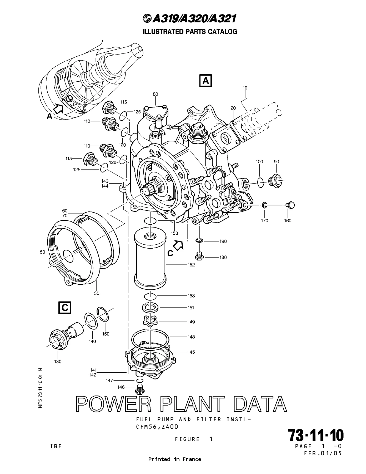
Across these sections the catalog gives you exploded assemblies with ballooned figure items, part numbers, nomenclature, usage codes, serial number applicability, effectivity by engine variant, and unit-per-assembly counts. Figure references point to the exact illustration where a component sits, and the effective-page listings at the front let you confirm which revision page applies to your aircraft configuration. For anyone maintaining, inspecting, or ordering parts for the fuel and control side of a CFM56-powered A319/A320/A321, this is the diagram-and-part-number layer that makes the rest of the maintenance task possible.
What This Catalog Enables
Use this Airbus A319 A320 A321 Illustrated Parts Catalog Chapter 73 Engine Fuel and Control PDF to identify fuel drain components, trace main fuel supply routing, break down fuel nozzle installations, confirm cooling air plumbing, locate hydromechanical unit parts, read electronic control unit configurations, reference sensor and probe installations, and verify fuel flow transmitter and differential pressure switch assemblies. The exploded views make it practical to see how parts nest together before you disassemble anything — which is exactly what you need when ordering replacements or confirming a configuration.
Why This Matters
Fuel and control parts on the A319/A320/A321 are configuration-sensitive. Serial number ranges, engine build standards, service bulletin effectivity, and pre/post SB variants are all called out in the tables. Working from the illustrated catalog means you match the part number to the correct configuration the first time, rather than discovering a mismatch after the component is on the bench. The figure-item tables also give you the nomenclature and unit-per-assembly counts that make receiving and inventory checks straightforward.
Instant PDF Delivery
This is a digital PDF download — no physical shipment, no waiting. Once your order is complete you can open the catalog on a laptop, tablet, or phone, print the specific figure pages you need for the hangar, and keep the full 676-page reference on hand for every fuel and control parts task on the A319, A320, and A321.


Reviews
There are no reviews yet.