
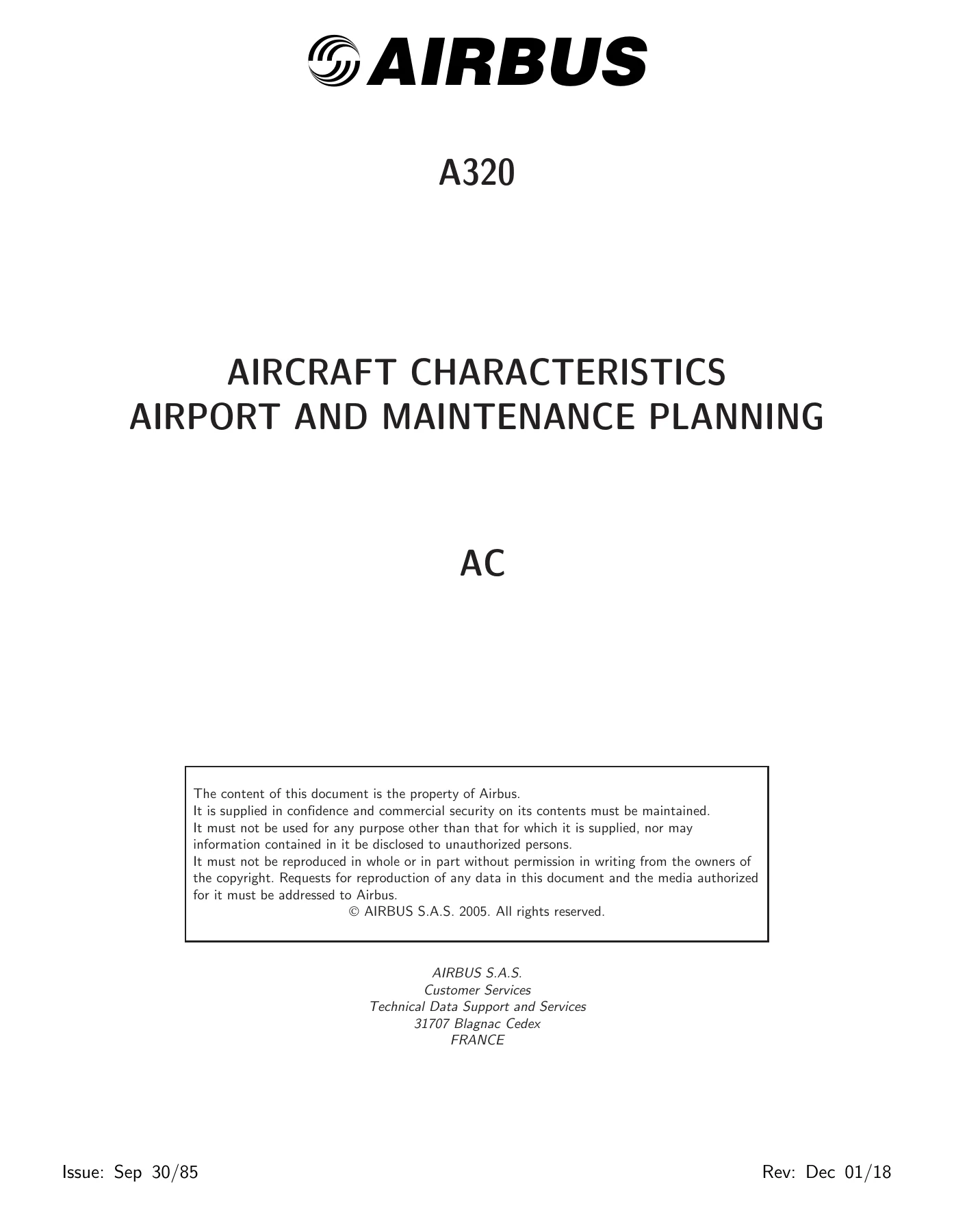
Airbus A320-200 & A320neo Aircraft Characteristics Airport and Maintenance Planning Manual (AC) – Rev 35
Original price was: $44.95.$27.95Current price is: $27.95.
The complete Airbus A320 Aircraft Characteristics – Airport and Maintenance Planning (AC) manual, Revision 35, covering A320-200 and A320neo with CFM56, IAE V2500, PW 1100G and CFM LEAP-1A engines. 402 pages of airport planning, ground maneuvering, terminal servicing, operating conditions and pavement data.
Description
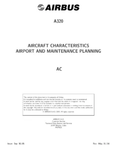
Airbus A320-200 & A320neo Aircraft Characteristics – Airport and Maintenance Planning (AC) Manual, Revision 35
This is the full Aircraft Characteristics – Airport and Maintenance Planning (AC) manual for the Airbus A320-200 and A320neo, Revision No. 35, dated December 1, 2018. It is the reference document airport operators, airlines, and Maintenance/Repair Organizations (MROs) use to plan airport infrastructure, ramp layouts, and maintenance facilities around the A320 Family. Coverage spans the classic A320-200 with wing-tip fences or sharklets and the A320neo with its two new engine options: the PW1100G PurePower from Pratt & Whitney and the LEAP-1A from CFM International.
File Details
- Manual type: Aircraft Characteristics – Airport and Maintenance Planning (AC)
- Manufacturer: Airbus
- Models covered: A320-200, A320neo
- Engines covered: CFM56, IAE V2500, PW 1100G, CFM LEAP-1A
- Revision: No. 35
- Revision date: December 1, 2018
- Language: English
- Page count: 402
- File format: PDF
Chapters Covered in the A320 AC Manual
- Chapter 1 – Scope: Introduction, Glossary
- Chapter 2 – Aircraft Description: General Aircraft Characteristics Data; General Aircraft Dimensions (Wing Tip Fence, Sharklet); Ground Clearances (Wing Tip Fence, Sharklet); Interior Arrangements (Plan View, Cross Section); Cargo Compartments; Door Clearances and Location; Escape Slides; Landing Gear (Twin-Wheel, Four-Wheel Bogie, Nose); Exterior Lighting; Antennas and Probes Location; Power Plant (CFM56, IAE V2500, PW 1100G, CFM LEAP-1A); Leveling, Symmetry and Alignment; Jacking for Maintenance; Jacking of the Landing Gear
- Chapter 3 – Aircraft Performance: General Information; Payload/Range – ISA Conditions; Take-Off Weight Limitation – ISA Conditions; Take-Off Weight Limitation – ISA +15°C Conditions; Aerodrome Reference Code; Landing Field Length – ISA Conditions; Final Approach Speed
- Chapter 4 – Ground Maneuvering: Turning Radii; Minimum Turning Radii; Visibility from Cockpit in Static Position; Runway and Taxiway Turn Paths (135° Runway to Taxiway, 90° Runway to Taxiway, 180° Turn on a Runway, 135° Taxiway to Taxiway, 90° Taxiway to Taxiway); Runway Holding Bay (Apron); Minimum Line-Up Distance Corrections; Aircraft Mooring
- Chapter 5 – Terminal Servicing: Aircraft Servicing Arrangements; Typical Ramp Layouts (Open Apron Bulk, Open Apron ULD, Gate); Full Servicing Turn Round Time Chart; Outstation Turn Round Time Chart; Ground Service Connections (Grounding Points, Hydraulic, Electrical, Oxygen, Fuel, Pneumatic, Oil, Potable Water, Waste Water); Engine Starting Pneumatic Requirements; Ground Pneumatic Power Requirements; Preconditioned Airflow Requirements; Ground Towing Requirements; De-Icing and External Cleaning
- Chapter 6 – Operating Conditions: Engine Exhaust Velocities and Temperatures (Ground Idle, Breakaway, Takeoff Power); Danger Areas of Engines (Ground Idle, Breakaway, Max Take Off Power); APU (APIC & Garrett)
- Chapter 7 – Pavement Data: General Information; Landing Gear Footprint; Maximum Pavement Loads; Landing Gear Loading on Pavement; Flexible Pavement Requirements – US Army Corps of Engineers Design Method; Flexible Pavement Requirements – LCN Conversion; Rigid Pavement Requirements – PCA Design Method; Rigid Pavement Requirements – LCN Conversion; Aircraft Classification Number – Flexible and Rigid Pavements
- Chapter 8 – Scaled Drawings
- Chapter 10 – Aircraft Rescue and Fire Fighting: Front Page; Highly Flammable and Hazardous Materials and Components; Batteries Location and Access; Wheel/Brake Overheat; Composite Materials; L/G Ground Lock Safety Devices; Emergency Evacuation Devices; Pax/Crew Doors; Emergency Exit Hatch; FWD and AFT Lower Deck Cargo Doors; Control Panels; APU Access Door; Aircraft Ground Clearances; Structural Break-in Points
What the Airbus A320 Aircraft Characteristics Manual Gives You
The AC manual is not a line-maintenance or repair guide – it is the planning-level document that tells airport engineers, airline operations teams and MRO facility planners everything they need to know about the physical and operational footprint of the A320-200 and A320neo before an aircraft ever arrives. Every weight variant from WV000 through WV019 for the A320-200 and WV050 through WV082 for the A320neo is documented, with individual maximum ramp, taxi, take-off, landing and zero-fuel weights tabulated.
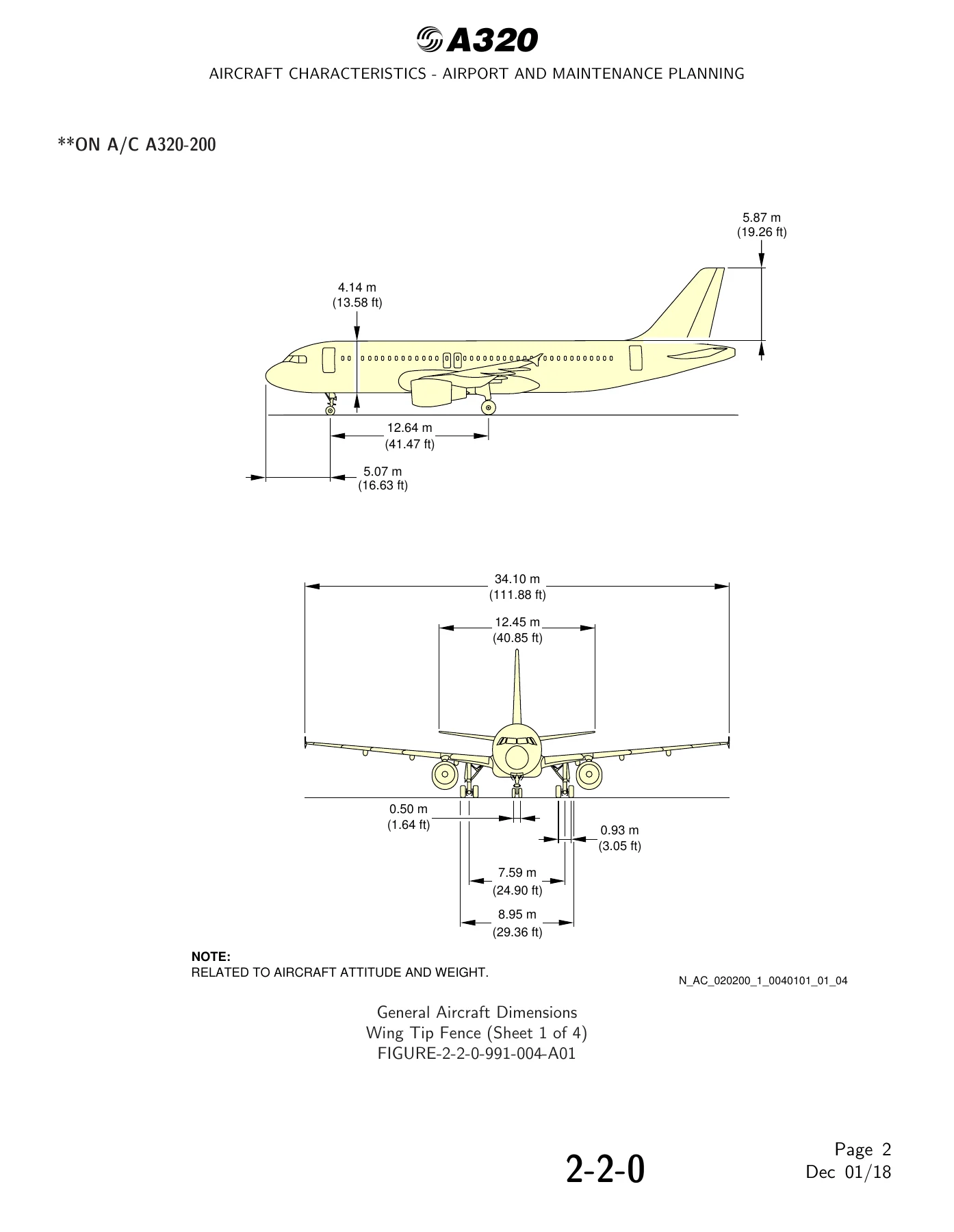
Aircraft dimensions are broken down by configuration – wing tip fence and sharklet – with overall length, fuselage width, wing span, wheel base, wheel track, and tail heights given in both metric and imperial units. Ground clearances are presented for passenger doors, cargo doors, service doors, engine nacelles, wing tips, flap tracks, ailerons, spoilers and leading edge slats, each measured under maintenance configuration, forward CG, aft CG and jacked conditions.
Interior layout planning is supported with plan-view and cross-section diagrams for single-class high-density, two-class, six-abreast wider aisle, wider seat, and four-abreast first-class arrangements, alongside cargo compartment locations, loading combinations, and usable volumes for forward, aft and bulk holds. Door clearance diagrams cover forward and aft passenger/crew doors, emergency exits, cargo compartment doors, main landing gear doors, radome, APU door and nose landing gear doors.
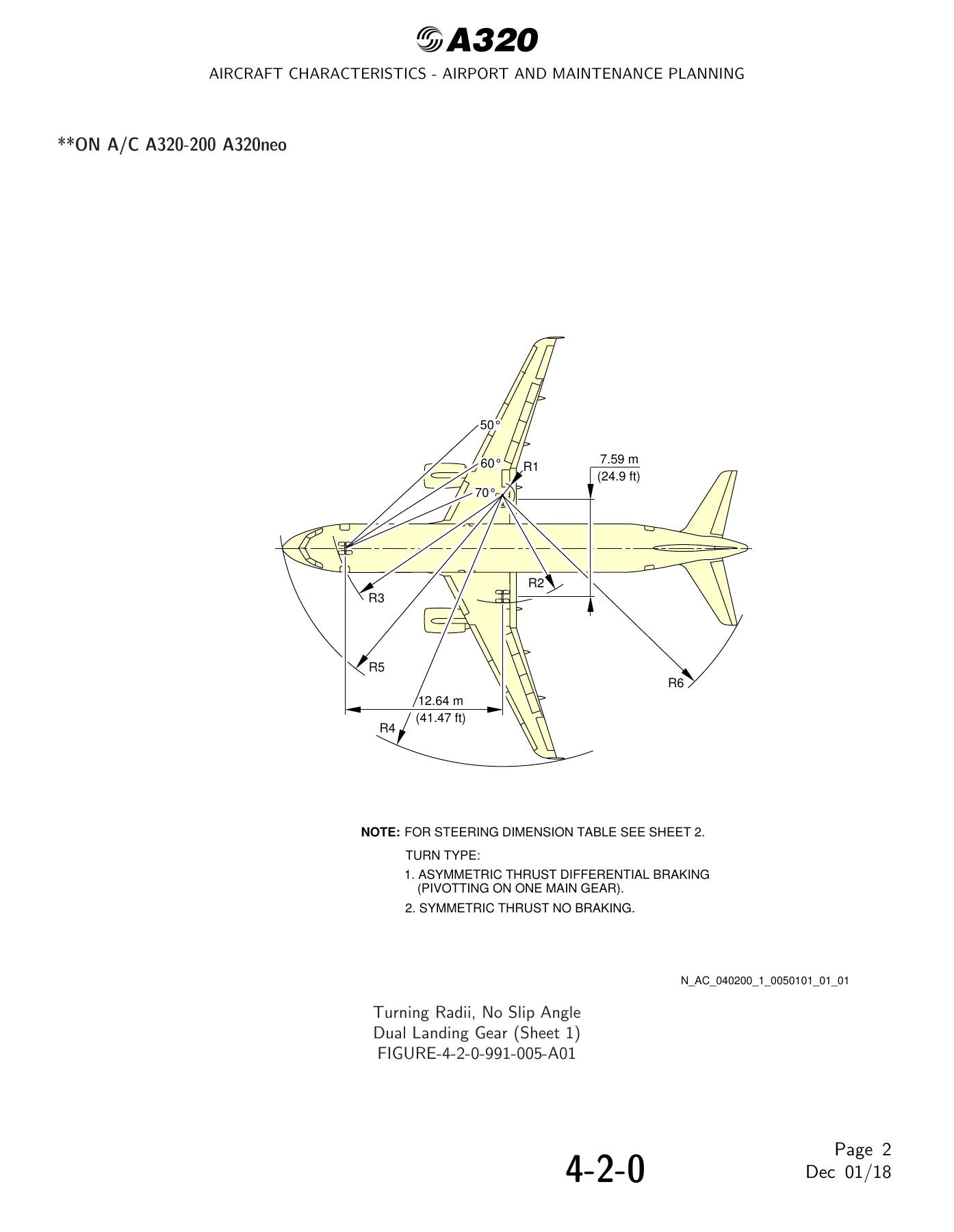
Ground maneuvering data includes turning radii, minimum turning radii, cockpit visibility angles, and full turn-path diagrams for 135° runway-to-taxiway, 90° runway-to-taxiway, 180° runway turn, 135° taxiway-to-taxiway and 90° taxiway-to-taxiway maneuvers, each with cockpit-over-centerline and judgemental oversteering methods. Minimum line-up distance corrections for 90° runway entry and 180° runway turn pad or runway width maneuvers are provided for TODA and ASDA.
Terminal servicing sections lay out full-servicing and outstation turn-round time charts, typical ramp layouts for open apron and gate operations, and every ground service connection point – fuel, hydraulic, electrical, oxygen, pneumatic, oil, potable water, waste water and grounding – with precise distances aft of nose, LH/RH offset from the aircraft centerline, and mean height from ground.
Engine operating conditions are quantified with exhaust velocity and temperature contours for the CFM56, IAE V2500, PW 1100G and CFM LEAP-1A at ground idle, breakaway power and take-off power, plus danger area diagrams defining inlet suction, entry corridor and exhaust wake boundaries for each power setting. APU exhaust velocities and temperatures are also charted.
Pavement data is a major section in its own right: landing gear footprints for every weight variant with tire sizes and pressures, maximum pavement loads at the tire-ground interface, landing gear loading on pavement charts, flexible pavement thickness design curves using the US Army Corps of Engineers method, rigid pavement design curves using the PCA method, and the full ACN table for flexible and rigid pavements across the operational weight variants.
Finally, the aircraft rescue and fire fighting section identifies highly flammable and hazardous materials, battery locations, wheel and brake overheat safety areas, composite materials, ground lock safety devices, emergency evacuation devices, and structural break-in points – the information a fire crew needs on scene.
Why This Manual Matters
Airport planning and MRO facility design cannot proceed on guesswork. This AC manual provides the certified, revision-controlled dimensional, weight, clearance, servicing and pavement data that engineers, planners and operational teams need to size taxiways, apron stands, hangars, de-icing bays, service roads and pavement thickness correctly. Because it is Revision 35 dated December 1, 2018, it reflects the current state of the A320-200 and A320neo program including the LEAP-1A and PW 1100G engine installations.
IMAGES PREVIEW
Instant PDF Delivery
This Airbus A320 Aircraft Characteristics – Airport and Maintenance Planning manual is delivered as a PDF download immediately after purchase. No shipping, no waiting – access it on any device, print the sections you need, and share with your planning or engineering team. Keep the authoritative A320 airport and maintenance planning data at hand whenever you need it.

Reviews
There are no reviews yet.