
Beechcraft Bonanza F33A F33C V35B A36 A36TC B36TC Wiring Diagram Manual 1999
Original price was: $39.95.$23.95Current price is: $23.95.
Complete Beechcraft Bonanza Wiring Diagram Manual for F33A, F33C, V35B, A36, A36TC and B36TC — 694 pages of electrical schematics, wire codes, reference designators and part numbers. Instant PDF download.
Description
Beechcraft Bonanza Wiring Diagram Manual — F33A, F33C, V35B, A36, A36TC, B36TC
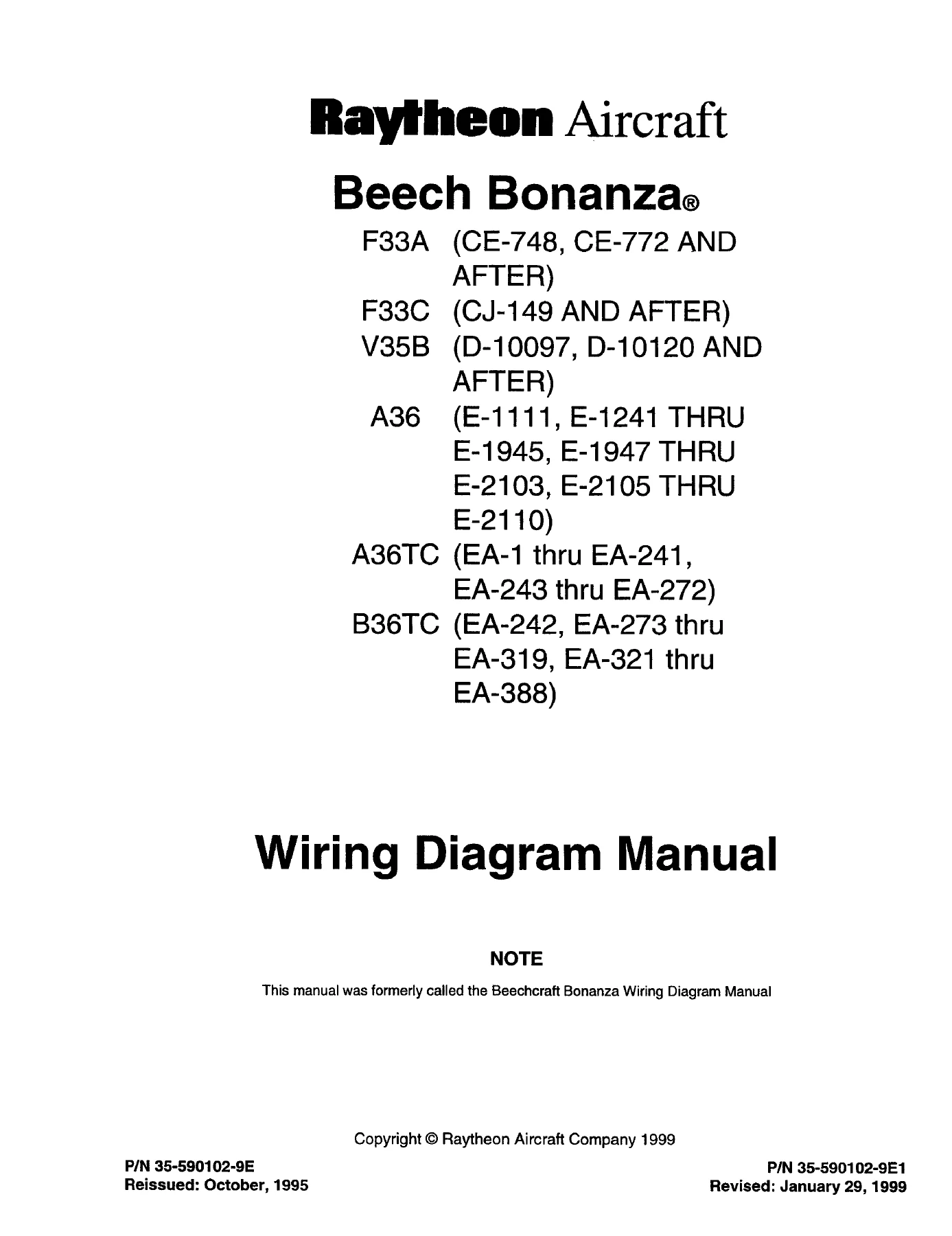
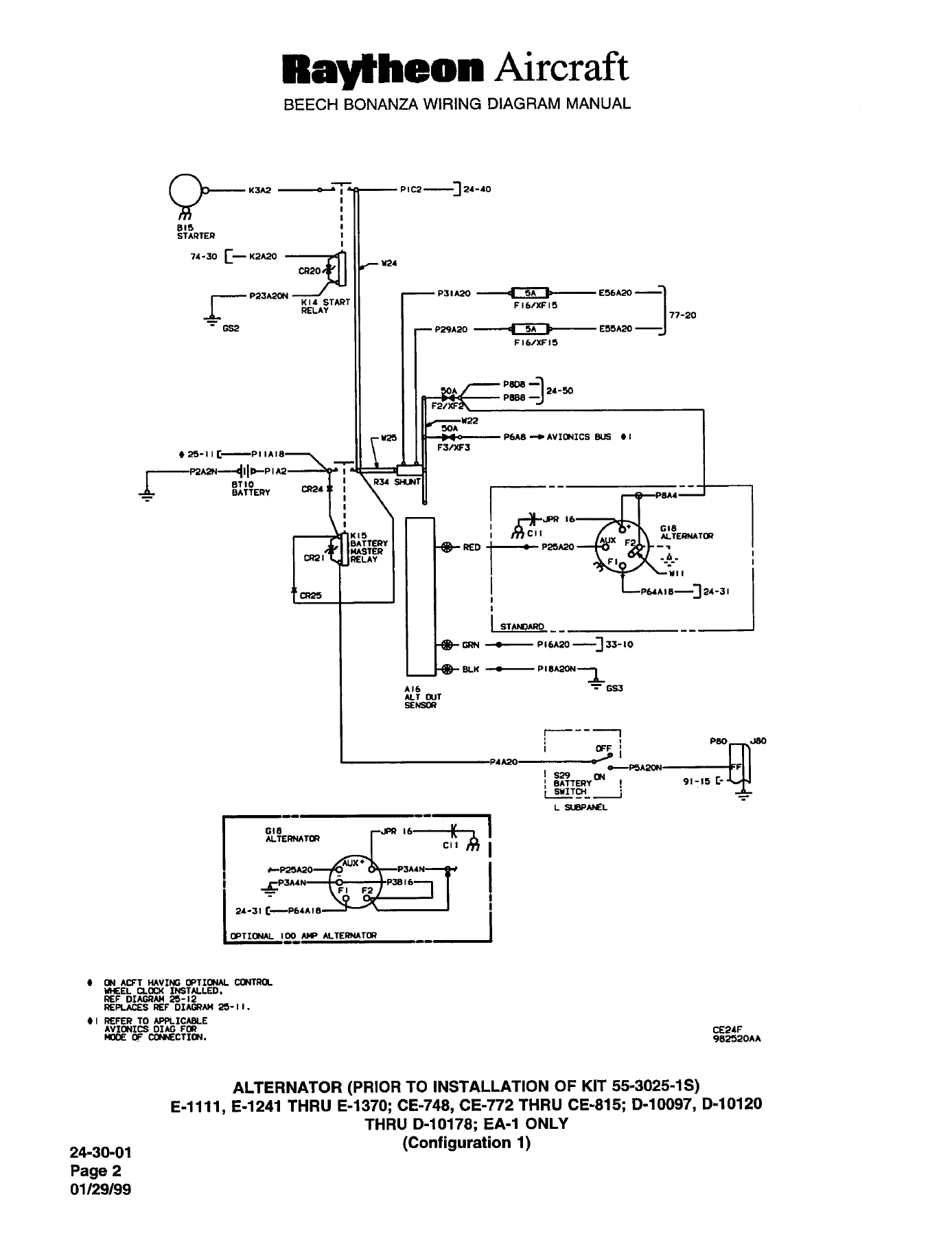
This Beechcraft Bonanza Wiring Diagram Manual is the point-to-point electrical reference for six Bonanza variants: the F33A, F33C, V35B, A36, A36TC and B36TC. Published by Raytheon Aircraft Company under document number 35-590102-9E1 and dated January 29, 1999, it delivers the complete wiring schematics, wire codes, component reference designators and equipment part numbers required to trace, test and repair the electrical systems of these aircraft. Every circuit is drawn in the schematic format used at the factory, with each wire identified by its printed aircraft wire code and every component keyed to a reference designator that maps directly to the equipment list.
File Details
- Manual type: Wiring Diagram Manual
- Brand: Beechcraft / Raytheon Aircraft
- Models covered: F33A, F33C, V35B, A36, A36TC, B36TC
- Document number: 35-590102-9E1
- Revision: E1 (January 29, 1999)
- Language: English
- Page count: 694 pages
- File format: PDF
Chapters Covered
- 21 — Air Conditioning (cooling, fresh-air vent blower, condenser door, compressor clutch)
- 23 — Communications (microphone switch, cabin speakers, grounding block)
- 24 — Electrical Power (alternator, voltage regulator, emergency power, external power, sub-panels)
- 25 — Equipment / Furnishings (cigarette lighter, panel and control wheel clocks, ELT transmitter)
- 27 — Flight Controls (stall warning, elevator trim, flap motor, flap position indicator)
- 28 — Fuel (auxiliary fuel pumps, fuel quantity indicating)
- 30 — Ice & Rain Protection (pitot heat, propeller anti-ice)
- 32 — Landing Gear (motor and relay, safety system, position indicator, throttle and airspeed warning)
- 33 — Lights (annunciator, map/compass/OAT/fuel select, instrument wedge and post lights, dimming, electroluminescent panel, flood, cabin, courtesy, taxi, beacon, strobe, navigation, landing)
- 34 — Navigation & Pitot/Static (turn coordinator, standby air pump gyro)
- 36 — Pneumatic (standby instrument air pressure kit)
- 39 — Electric Panels, Parts and Instruments (annunciator light PCBs, fuel quantity PCBs, flap position PCB, electrical equipment PCB)
- 73 — Engine Fuel Systems (fuel flow indicating)
- 74 — Ignition (magneto switching, starter vibrator)
- 77 — Engine Indicating (engine instrument cluster, turbine intake temperature)
- 91 — Charts (junction box assemblies, connector charts for wheel well access, instrument panel grounding, junction box disconnects, crossover disconnect, glareshield connector)
Beyond the system schematics themselves, the manual opens with the introduction, alphabetical index, and the reference designator and part number indexes — the three lookup tools that make the diagrams usable in practice. The reference designator index lists every component by its letter-number call sign alongside the GAMA/ATA chapter code and Beechcraft part number. The part number index performs the same task from the opposite direction, letting you start with a part number and locate the diagram where it appears. Together they turn the schematic set into a searchable-by-index reference rather than a stack of drawings.
How the Wiring Diagrams Are Organized
Diagrams follow the GAMA Specification No. 2 chapter and sub-chapter numbering system, which means each diagram is filed under the same ATA-style number you would find in the Beechcraft Bonanza Maintenance Manual or Parts Catalog. The chapters in this Beechcraft Bonanza Wiring Diagram Manual cover air conditioning, communications, electrical power, equipment and furnishings, flight controls, fuel, ice and rain protection, landing gear, lights, navigation and pitot/static, pneumatic, electric panels and instruments, engine fuel, ignition, engine indicating, and the charts chapter. Non-applicable chapters are listed in the introduction, so there is no wasted searching through empty sections.
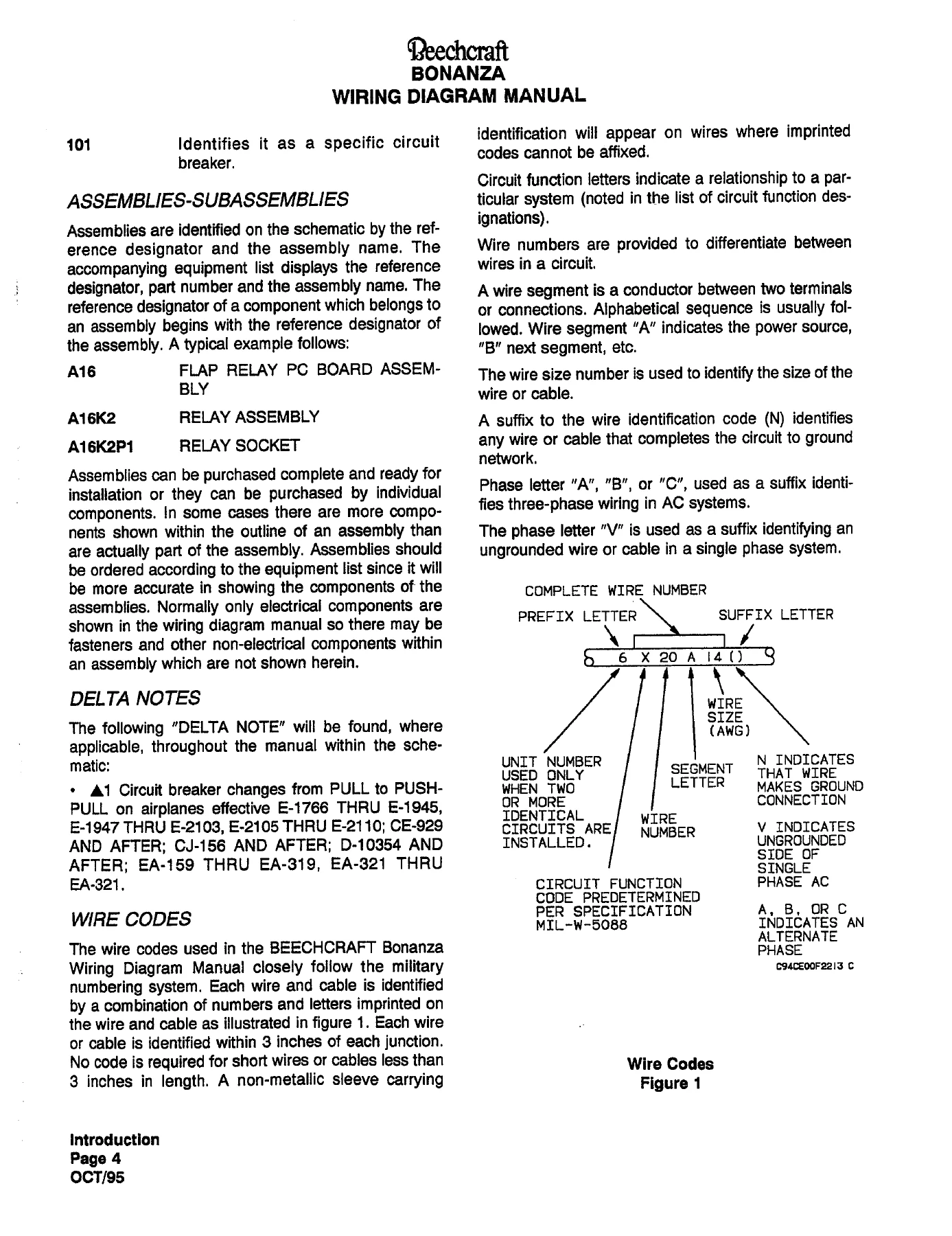
Every wire in the manual is labeled with the aircraft’s actual printed wire code — the prefix letter that identifies the circuit function, the wire number, the segment letter, the wire size in AWG, and the suffix letters that identify ground connections and single-phase or three-phase AC. A printed key (Wire Codes Figure 1) shows exactly how each element of the code is built so that a technician can decode any wire encountered in the aircraft, and a full list of circuit function designations is provided for reference.
Because the diagrams are drawn point-to-point, all connector inserts are shown from the back of the connector, and terminal board and bus bar positions appear exactly as they sit in the aircraft. That convention matters when you are ringing out a circuit in a cramped wheel well or behind an instrument panel — the drawing matches what you see when you look into the back of the connector, not the front.
Reference Designators and Equipment Lists
Every schematic is accompanied by an equipment list arranged in alphanumeric order of the reference designators, giving the part number, description and the installation zone for each component. Assemblies such as the annunciator light PC board, the flap position PC board, the fuel quantity indicator PC boards and the electrical equipment junction box are broken out into their individual sub-components — relays, diodes, resistors, capacitors and connectors — so that a board can be repaired component-by-component rather than replaced whole. Reference designators for sub-components begin with the assembly’s designator (for example A19A1R7 is resistor 7 on the annunciator light PCB within the electrical equipment junction box assembly A19).
Charts and Connectors
The charts chapter (91) is where the large connector pin-out tables live. It includes the left and right wheel well access connectors (P/J10 and P/J11), the instrument panel grounding block (P/J80), the junction box disconnect (P/J54), the crossover disconnect (P/J85), the glareshield connector (P/J31), the electrical equipment junction box (91-01-01 and 91-01-02), the annunciator light junction box assembly (91-02-01 through 91-02-03) and the landing gear safety system relay assembly (91-03-01). Each chart lists the wire number, the reference diagram it belongs to, and the pin assignment, so you can cross-check an individual wire from its code back to the system schematic.
Why This Manual Matters
Electrical faults in a Bonanza rarely announce themselves. A flickering annunciator, a flap that runs slowly, a beacon that stops turning, or a fuel gauge that reads low when the tanks are full can each trace back to a single wire, connector pin or diode in a circuit that runs half the length of the airframe. Without the correct schematic, tracing that circuit means guessing at wire color, continuity and pin assignments. With this manual, the trace becomes a lookup: find the circuit by system chapter, identify the wire by its printed code, follow it through the charted connector, confirm the pin, and test the right terminal the first time. That is the difference between a two-hour diagnosis and a two-day one — and between a repair that lasts and a repair that comes back.
The manual also supports the work that has to be documented. When you replace a relay or diode, the equipment list gives you the Beechcraft part number and the installation zone, so the logbook entry can name the correct component rather than a generic substitute. When you troubleshoot a power feed that runs through a shunt, a limiter base or an avionics bus, the schematic shows you exactly where the feed originates, where it branches, and what protects it — including circuit breakers and fuses by their reference designator.
Get the Beechcraft Bonanza Wiring Diagram Manual — Instant PDF
IMAGES PREVIEW
This Beechcraft Bonanza Wiring Diagram Manual for the F33A, F33C, V35B, A36, A36TC and B36TC is delivered as an instant PDF download — no shipping, no waiting, no damaged binders. Open it on a laptop or tablet in the hangar, print only the pages you need for a job, and keep the digital copy on file for the next one. Whether you are chasing an intermittent fault, adding an avionics upgrade, or just want to understand how a particular circuit in your Bonanza actually works, this is the reference the airframe was designed against.


Reviews
There are no reviews yet.