
Bell B25B 6×6 ADT MKII Parts Manual 1998 – Illustrated PDF Parts Catalog
Original price was: $29.95.$17.95Current price is: $17.95.
Complete illustrated parts manual for the Bell B25B 6×6 ADT MKII articulated dump truck. Document 870159, September 1998 issue. Every major system broken down with exploded views and keyed part numbers – engine, powertrain, hydraulics, pneumatics, electrical, frame and body. Instant PDF download.
Description
Bell B25B 6×6 ADT MKII Parts Manual – September 1998 Edition
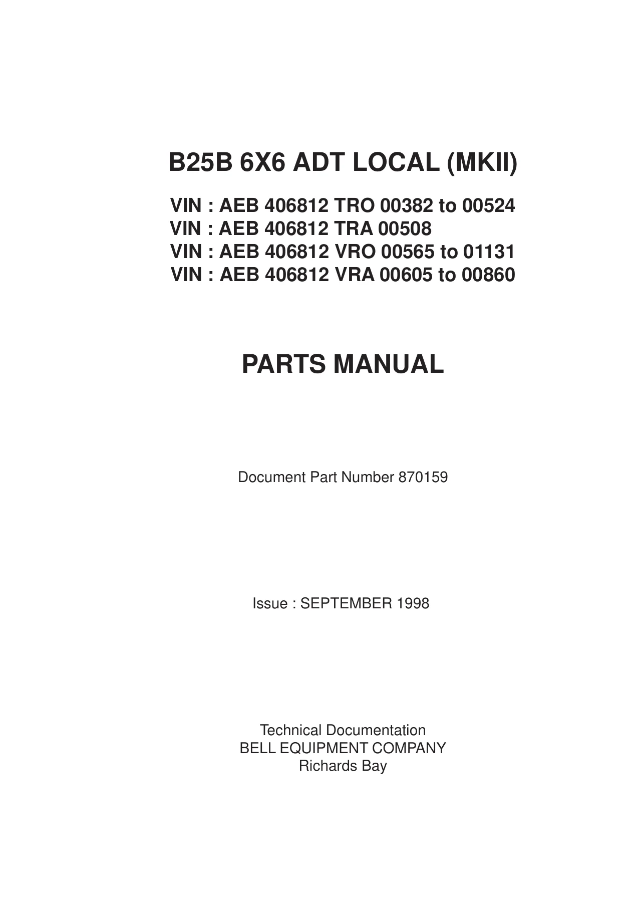
This is the complete illustrated parts manual for the Bell B25B 6×6 ADT MKII articulated dump truck, published by Bell Equipment Company’s Technical Documentation Department in September 1998 under document number 870159. Every component group on the machine is broken down into exploded-view illustrations keyed to part numbers, quantities and descriptions, so you can identify exactly what you need before you order. Whether you are replacing a failed hydraulic hose, rebuilding a differential, or hunting down a bracket for the cab interior, the Bell B25B 6×6 ADT MKII Parts Manual puts the correct part number in front of you, every time.
File Details
- Manual type: Illustrated Parts Manual
- Machine: Bell B25B 6×6 ADT LOCAL (MKII)
- Document number: 870159
- Issue: September 1998
- Publisher: Bell Equipment Company, Technical Documentation (Richards Bay)
- Language: English
- File format: PDF
- Page count: 327 pages
Serial Numbers Covered
- AEB 406812 TRO 00382 to 00524
- AEB 406812 TRA 00508
- AEB 406812 VRO 00565 to 01131
- AEB 406812 VRA 00605 to 00860
Chapters Covered
- Section 1 – General Information: technical documentation bulletins, list of abbreviations, ordering of parts, machine dimensions, serial number plates, service kits
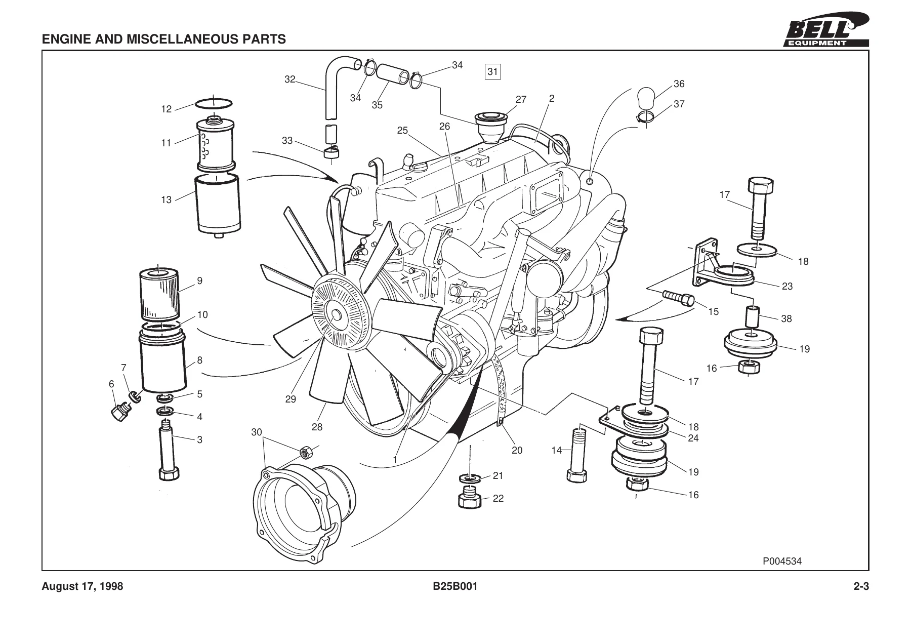
- Section 2 – Engine: engine and miscellaneous parts, engine coupling, air cleaner system (ADE 366TI), air cleaner, pre cleaner, exhaust system, fuel system, throttle assembly, stop cable assembly, cooling system (air to air), cooling system header tank
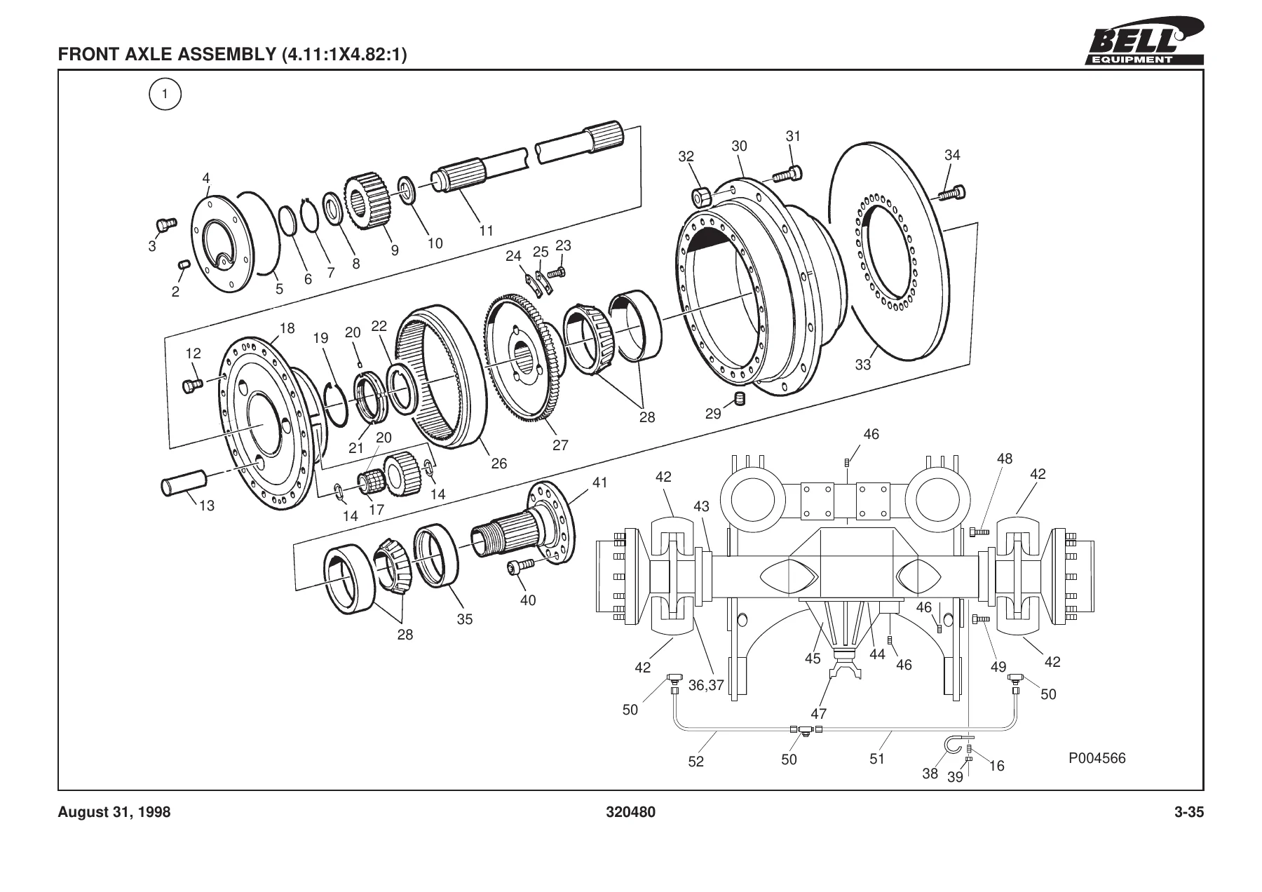
- Section 3 – Power Train: transmission and miscellaneous parts, transmission differential lock actuator, oil cooler assembly, propshaft layout and assemblies, driveline, park brake actuator, mechanical C-clamp brake assembly, front axle and miscellaneous parts, front axle assembly, rear axle mountings, thru-drive axle assembly, rear drive axle assembly, differential assembly, brake assembly, brake caliper, brake caliper cover plates, wheel assembly, special tools
- Section 4A – Hydraulic System: hydraulic system, hydraulic tailgate system (optional), hydraulic tank, emergency steering, flow amplifier, hydraulic filter / breather, control valve, tip cylinder, steering cylinder, special tools
- Section 4B – Pneumatic System: front pneumatic system, rear pneumatic system, air spring assembly, solenoid valve, park brake valve, pressure protection valve, levelling valve, unloader valve with integral air drier assembly, brake valve, control valve, brake valve adaptor, air / hydraulic brake actuator
- Section 4C – Electrical System: starting / charging, lighting, stop light / horn, reverse and exhaust brake, gauges and warning lights, indicator / hazard, blower and wiper, aircon and wiper, EST 17 transmission, EST 25 transmission, connectors, electronic speedo and other accessories, instrument panel assembly, cold start instrument panel, distribution box, battery clamps and cables, windscreen wiper assembly, horn assembly, special tools
- Section 5 – Frame and Body: cab and cowling, bonnet latch, cab exterior fittings, door handle assembly, cab interior fittings, seat assembly, steering column, adjustable steering column, air conditioner assembly, hydraulic tailgate, bin heater, blower assembly, front frame, articulation and oscilation, steering cylinder mountings, rear frame, tip cylinder mountings, decal layout
What the Bell B25B MKII Parts Catalog Covers
The B25B 6×6 ADT MKII parts catalog is organised so you move straight from system to section to component. Engine chapter covers the Atlantis Diesel Engines (ADE) 366TI air cleaner installation, engine coupling, exhaust and cooling plumbing, fuel and throttle hardware. Power Train leads you through ZF transmission mounting, propshaft variations by build date, thru-drive and rear drive axle internals, differential assemblies at 4.11:1 and 4.82:1 ratios, brake calipers, and wheels with the 23.5R25 tyre configuration shown.
The systems half of the manual is where the illustrated parts catalog really does its job. Hydraulics runs from the pump, flow amplifier and steering valve through to the tip cylinders, oil cooler, hydraulic tank and the optional tailgate circuit. Pneumatics covers front and rear air systems for both pre-February 1997 and later build periods, plus air springs, solenoid valves, the park brake valve, pressure protection valve, levelling valve, unloader valve with integral air drier, brake valve and air / hydraulic brake actuator. Electrical contains full wiring diagrams from starting and charging through to lighting, reverse and exhaust brake, gauges and warning lights, indicator and hazard, blower and wiper, air conditioning, EST 17 and EST 25 transmission circuits, connector pin-outs, instrument panel, battery and earth cabling.
Frame and Body chapter documents cab, cowling, bonnet latch, exterior fittings, door handles, interior trim, seat assembly, steering column, air conditioner, bin heater, front and rear chassis, articulation and oscilation joint, steering and tip cylinder mountings, and the decal layout.
How the Listings Are Organised
Every illustrated breakdown is supported by a parts list showing item number, part number, quantity and description, plus remarks where a part changed at a specific build date. For example, propshaft assembly part numbers vary between pre-14/01/97, pre-02/04/97 and later machines, and axle assemblies differentiate between 4.11:1 and 4.82:1 differential ratios. Service kits are listed separately at the start with recommended SMR intervals (100, 250/750, 500 and 1000 SMR), so you can order a complete filter and gasket set instead of chasing individual part numbers.
Who This Bell B25B 6×6 ADT MKII Parts Manual Is For
Fleet workshops and independent mechanics servicing B25B MKII articulated haulers use this manual to place accurate parts orders, cross-check superseded numbers, and confirm exactly which configuration applies to a specific machine by serial range. Parts managers use the exploded views to identify brackets, seals, clamps and fittings that are otherwise hard to describe over the phone. Owners running their own maintenance use it to keep the right spares on the shelf and avoid downtime waiting on a wrong part.
IMAGES PREVIEW
Instant PDF Delivery – Start Ordering Correct Parts Today
The Bell B25B 6×6 ADT MKII Parts Manual delivers the factory-published parts data for your machine in a single 327-page PDF you can open on any device. No shipping, no waiting for a printed binder – the moment your order is confirmed, the download link is ready. Print the pages you need for the workshop, keep the full catalog on a tablet or laptop in the service truck, and look up part numbers by system, illustration or serial range in seconds. When a hydraulic hose bursts or a differential needs an overhaul, having the correct part number on hand means the machine is back in service faster, with fewer wrong-part returns and less guesswork. Grab the PDF today and get your next parts order right the first time.

Reviews
There are no reviews yet.