
Bell B25C 6×6 MkII Parts Manual 872043-01 – Feb 2001 Illustrated ADT Parts Catalog PDF
Original price was: $34.95.$22.95Current price is: $22.95.
Bell document 872043-01 illustrated parts manual for the B25C 6×6 MkII articulated dump truck. 447-page PDF with exploded views, Bell part numbers, quantities, engine/transmission/axle breakdowns, hydraulic and electrical diagrams, and a full February 2001 VIN upgrade section.
Description
The Bell 872043-01 B25C 6×6 MkII Parts Manual is the illustrated spare-parts catalogue Bell Equipment issued for the B25C 6×6 MkII articulated dump truck. Document number 872043-01, Revision 01, first issued in October 1999 and last updated in February 2001, is the reference Bell parts counters, fleet workshops and independent heavy-equipment mechanics use to identify and order components for this exact machine. Every illustrated breakdown is paired with a matching parts list showing item numbers, Bell part numbers, quantities, descriptions and remarks, so a part can be found on the drawing and quoted straight from the page.
File Details
- Manual type: Illustrated parts manual / spare-parts catalogue
- Brand: Bell Equipment
- Model: B25C 6×6 MkII articulated dump truck (ADT)
- Document number: 872043-01
- Revision: 01
- Machine numbers: 409812-00, 409812-01
- First issue: October 1999
- Latest update: February 2001
- Language: English
- Page count: 447 pages
- File format: PDF
Chapters Covered
The manual is arranged into eight numbered sections, each built as an illustrated breakdown with its supporting parts table.
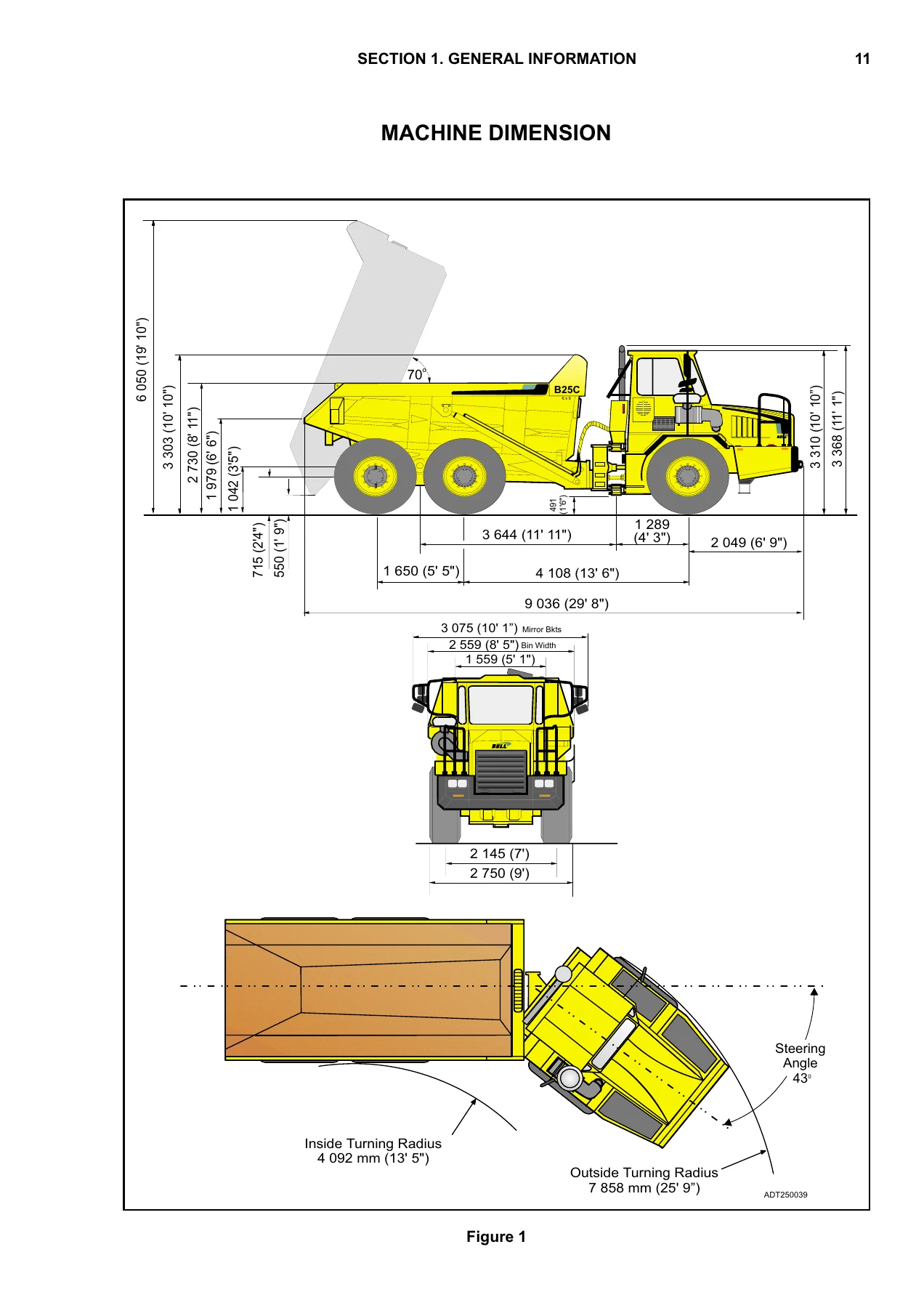
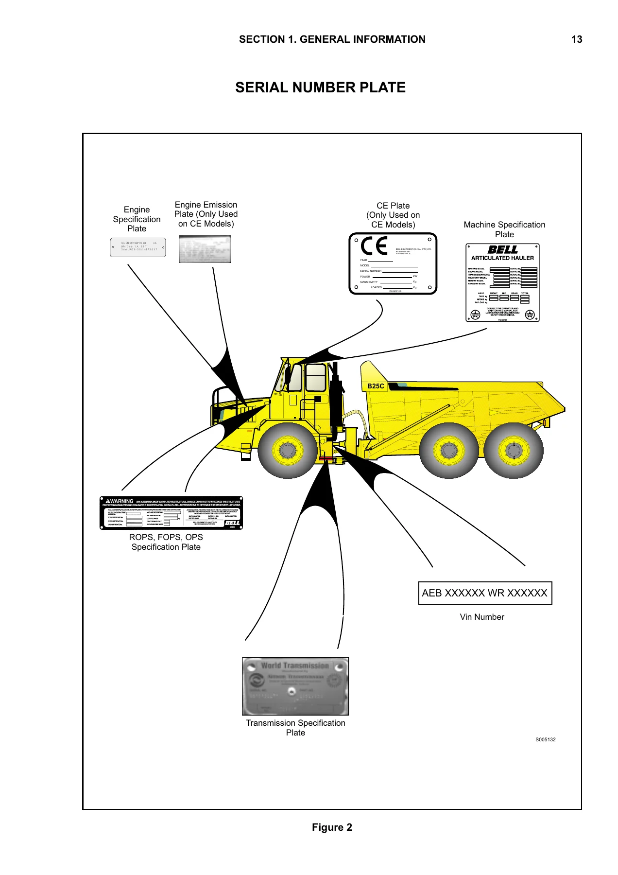
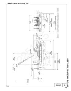
- Section 1 – General Information: VIN identification and structure, bulletin record sheet, list of abbreviations, ordering-of-parts instructions, machine dimensions and turning radius, specification plate locations.
- Section 2 – Engine: Engine and miscellaneous parts (Revision 00 and 01), engine remote drain system, engine connection kit, air cleaner system and air cleaner, pre-cleaner, exhaust system (Revision 00 and 01), bin heater kit, fuel system, throttle-to-engine linkage, throttle position sensor linkage, engine shutdown solenoid, engine cooling package (Revision 00 and 01), engine cooling system (Revision 00 and 01), air cooler system, fan guard kit (optional).
- Section 3 – Power Train: Transmission and miscellaneous parts, transmission remote drain system, PTO model 266, transmission cooling system, transfer case miscellaneous parts and assembly (7C input flange, 8.5C output flange, emergency steering pump assembly), park brake and actuator, drive train layout, propshafts and driveline, front axle and miscellaneous parts, remote-mounted axle breathers, front / middle / rear axle assemblies, differential assemblies, hub assembly, brake assembly, wheel assembly.
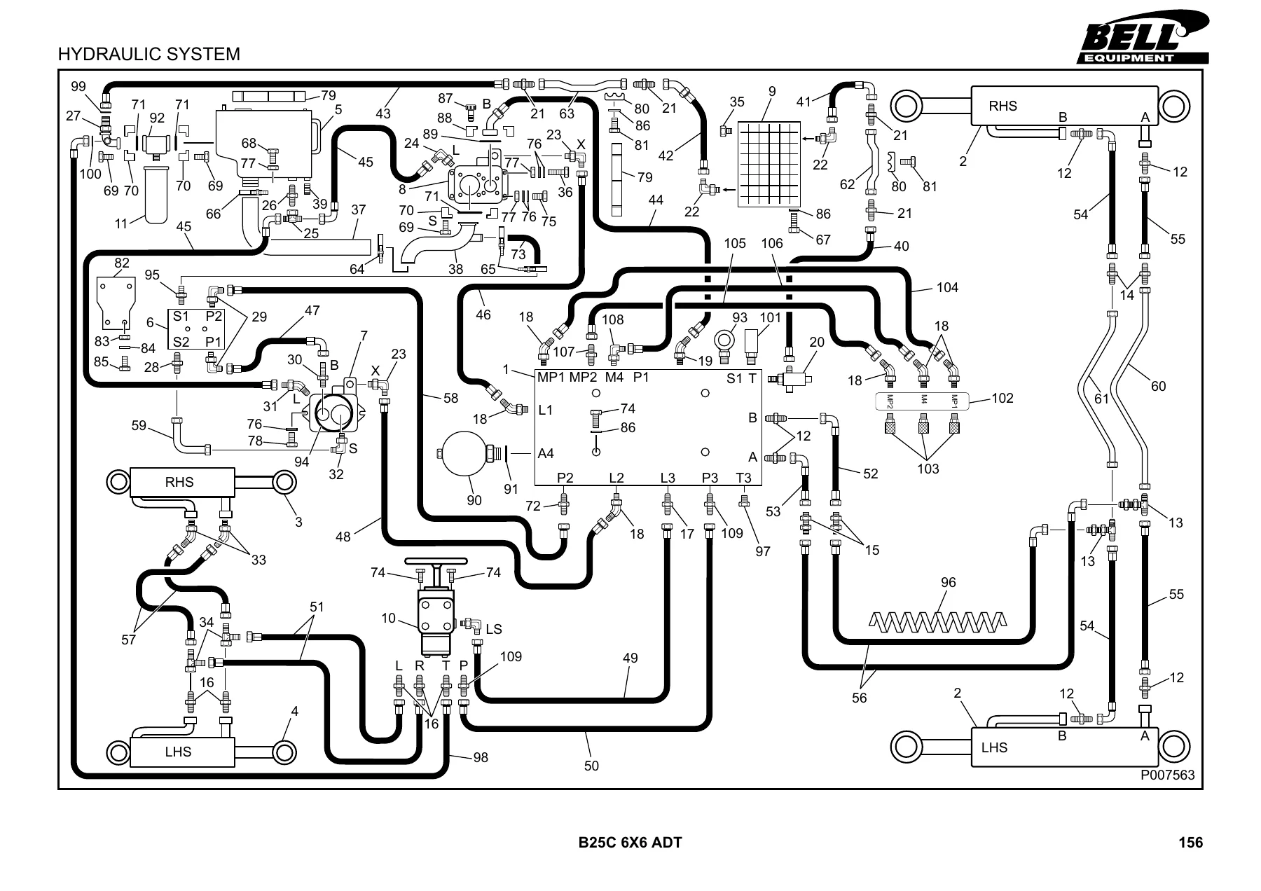
- Section 4 – Hydraulics: Hydraulic system layout, brake system, hydraulic tank, hydraulic filter assembly, hydraulic cooler assembly, hydraulic block front and rear views, hydraulic pressure test points, check valve block, steering control unit, service pump, rotation pump, foot brake valve, steering cylinder LHS and RHS, tip cylinder, hydraulic foot brake pedal.
- Section 5 – Pneumatics: Pneumatic system front and rear, air spring assembly, solenoid valve, levelling valve, double check valve, tip lever, unloader valve with integral air drier assembly, tyre inflation kit (optional), air horn kit (optional).
- Section 6 – Electrics: Earth straps and harness earth points, electrical harnesses and connectors for front and rear chassis, cab electrical harness and components, starting and charging circuit, warning lights, MFA 10 circuit, illumination, turn indicators and hazards, brake light and exhaust brake, air conditioner and blower, blower and wiper, cold start, beacon and cigarette lighter, battery balancer and radio cassette, bin / gear hold / electric park brake, Allison transmission WTEC III version 8 circuit, electric mirrors (optional), reverse lights and cooler fan and purge unit, connector pinout detail pages, instrument panels (centre, RHS, shift tower), air conditioner control units (up to and from VIN AEB408812XR020058), batteries, clamps and cables, circuit breaker box.
- Section 7 – Frame and Body: Bonnet assembly and latch, cab assembly and mountings, mirrors, door, handle assembly, windows, wiper and motor, reservoir, floors, interior trim, seats and seat assembly, instrument panels, steering column, interior light, interior and exterior fittings, mudguard and related parts, soundproofing, rear access steps, air conditioner layout, blower layout, condenser assembly (optional), blower assembly, front chassis, light mountings, rear chassis (Revision 00 and 01), bin repair and liner kits, mechanical autogate kit, fuel tank, battery box, articulation and oscillation assembly, steering cylinder mountings, tip cylinder mountings, decals (Revision 00 and 01), warning triangle.
- Section 8 – VIN Upgrade from February 2001: Revised exhaust system, cab interior trim and floor underlay, throttle position sensor linkage, LHS and RHS steering cylinders, steering cylinder mountings, tip cylinder, tip cylinder mountings, cab door, front chassis – each cross-referenced against the exact VIN from which the new parts apply.
Because the book opens with VIN structure and machine number identification, every later section can be matched against the actual serial range of the machine on the workshop floor. Dimensional drawings, specification-plate location diagrams, hydraulic schematics, pneumatic schematics and full wiring circuits for the B25C 6×6 MkII are included in the same file, so the manual serves both as a parts-ordering tool and as a working reference for anyone rebuilding, servicing or restoring one of these articulated dump trucks.
Section 8 VIN upgrade breakpoints included
The February 2001 revision level (Rev 01) is a genuine upgrade on earlier printings, and Section 8 lists the specific components that changed for machines built after the listed VIN thresholds. Breakpoints printed in the manual include AEB4098121R010172, AEB4098121R010189, AEB409812YR010147, AEB409812YR010169 and AEB408812XR020058. Checking the machine against these VINs before ordering an exhaust stack, steering cylinder, tip cylinder, cab door, cab interior trim, throttle position sensor linkage or front chassis is the difference between receiving the correct part and paying return freight on the wrong one.
What the B25C 6×6 MkII parts manual lets you do
Use the illustrated breakdowns to strip a component down to its individual parts, then quote every nut, bolt, washer, seal, bearing, hose, clamp, bracket, shim and gasket using its Bell part number, description and required quantity. Trace hydraulic hose routing, pneumatic circuit runs and electrical harness paths across the full machine. Confirm the engine side of the powertrain is documented for the Mercedes-Benz OM366LA installation and that the transmission is documented for the Allison WTEC III version 8 electronics used on this truck. Look up the correct caliper, rotor, disc, pad, hub, side shaft, differential assembly and planetary hub kit for the front, middle and rear axles. Read the decal set (Revision 00 and Revision 01) so the correct warning, torque and maintenance decals can be re-ordered for a repaint or restoration.
Why buy this specific document
A generic multi-model Bell catalogue is not the same as having 872043-01 in front of you. This is the manual Bell Equipment’s own Technical Documentation Department produced for this exact build number, with the part number sequences that were current at the February 2001 update. Because the B25C 6×6 MkII sat across a mid-life upgrade, at least one part in the cooling package, exhaust, steering and tip cylinder assemblies exists in both an early and a late version, and Section 8 is where that distinction is drawn. That level of detail is only available in the document number printed on the front cover, not in a generic parts list.
Delivery
IMAGES PREVIEW
Supplied as an instant-download PDF. No physical book to ship, no courier delay, no risk of losing a paper copy in the workshop. Open it on a laptop, tablet or phone, print the pages that matter for the bench, or attach the relevant page to a parts enquiry and email it to your Bell dealer or aftermarket supplier. Works with any standard PDF reader.
Reviews
There are no reviews yet.