★ TRUSTED BY 321,897+ PROFESSIONALS WORLDWIDE
🏒
Trusted Business
Verified & Licensed
πŸ›‘οΈ
Virus Free Files
100% Safe Downloads
πŸ”’
Secure Payment
SSL Protected
⚑
Instant Delivery
Available Immediately
Sale!

Bell B25D Mk 6.1 ADT Parts Manual 2010 – A825D61 Rev A PDF

Original price was: $39.95.Current price is: $24.95.

Complete Bell B25D Mk 6.1 ADT illustrated parts manual, document 872262, First Issue Revision A (January 2010). Covers A825D61 across Tier 2 and Tier 3 engine builds – engine, drivetrain, hydraulics, pneumatics, electrical, frame and body, service kits, special tools and numerical index.

⚑
Instant PDF Download
Available immediately
πŸ’Ύ
Save to Your Device
Download & keep forever
πŸ›‘οΈ
Antivirus Scanned
100% virus-free
🌍
Trusted Worldwide
175,000+ customers

Description

This is the complete Bell B25D Mk 6.1 ADT illustrated parts manual published under document number 872262 – the First Issue, Revision A edition released in January 2010 for the A825D61 machine. Prepared by the Technical Documentation Department of Bell Equipment Co., this Bell B25D Mk 6.1 ADT parts manual covers the B25D articulated dump truck across both the Tier 2 and Tier 3 engine builds, giving parts counter staff, workshop technicians and owners a complete illustrated breakdown of every major assembly on the machine.

File Details

  • Manual type: Illustrated parts manual
  • Document number: 872262
  • Machine: Bell B25D Mk 6.1 ADT – A825D61
  • Edition: First Issue, Revision A
  • Publication date: January 2010
  • Publisher: Bell Equipment Company SA (Pty) Limited
  • Language: English
  • File format: PDF
  • Approximate length: 678 pages
  • Coverage: Engine Tier 2 and Engine Tier 3 build variants

Chapters Covered

  • Section 1 – General Information: engine Tier identification, PIN structure, PLD decal details, parts ordering procedure
  • Section 2A – Engine Tier 2: crankcase, timing cover, oil pan and dipstick, cylinder head and valves, rocker arm, cylinder head cover, crankshaft and flywheel, connecting rod and pistons, camshaft and timing parts, injection pump, fuel lines, fuel filter, flamestart system, turbocharger, air compressor, intake manifold, exhaust manifold, electrical equipment, starting motor, alternator, oil pump, oil filter and oil cooler, water pump, fan, engine mountings, aircon compressor, exhaust system, air intake, air cleaner, fuel system, fuel-water filter, handlift pump and pre-filter, engine cooling system
  • Section 2B – Engine Tier 3: same sub-section structure as Section 2A for the Tier 3 OM906LA build
  • Section 3 – Drivetrain: transmission misc parts, transmission housing, oil supply and control insert, oil supply cover plate, retarder valve, gearbox planetary, coupling, brake sections D to G, output, shift control and valve blocks, throttle valve, transmission dipstick, oil sump, torque converter, power take off, heat exchanger, transmission cooling system, dropbox components, park brake and park brake assembly, propshafts, front / middle / rear axles, differential assemblies, clutch configurations, thru drive and oscillation joint, planetary hub, wheel sets
  • Section 4 – Hydraulics: hydraulic system cab details A and B, brake pedal, steering control valve, emergency steering pump check valve, emergency steering pumps (standard, alternate and bi-directional), cab tilt hydraulic kit and cylinder breakdown, VOAC block and valve positions, steering cylinders, front chassis, main pump delivery, damper assembly, accumulator kits for South Africa and Europe, hydraulic pump, steering cylinder assembly, hydraulic tank misc parts, rear chassis hydraulic system, tip cylinder breakdown for both early and later VIN ranges
  • Section 5 – Pneumatics: cab pneumatic kit, air horn kit, pneumatic block assembly, front chassis pneumatic system, purge tank valve and breakdown, air drier kit, air drier repair kit, 10L reservoir kit, rear chassis pneumatic kit
  • Section 6 – Electrical: cab harness details A to C, cab fuse and relay panel components, windscreen wiper kit, transmission harness, rear view mirror electrical kit and mirrors, load lights, beacon, work lights, rear facing work light, memory module, satellite kit, radio, rear camera, reverse monitor, emergency brake, engine harness, light breakdowns, artic harness, battery box, front chassis transmission, fuel heater, head light grilles, rear harness, OBW system, strain gauge kit, and the complete connectors index across eight sheets
  • Section 7 – Frame and Body: cab assembly, cab shell, cab/bonnet interface seal, HVAC sealing, window guards, handrails and cab mountings, rear view mirror brackets, cab door assembly, cab windows, window catches, HVAC door, cab interior parts and hatches, floor mat and interior panels, roof headliners, operator and trainer seat installation, high back seat installation, seat base assembly, steering column and column parts, cab sound foam, cab air ducting, aircon drier unit and piping, aircon unit breakdown, aircon front chassis, hydraulic tank misc parts, hydraulic tank filter assembly, front chassis kit, bonnet kit details A and B, bonnet catch, grill, belly plate, mudguards, battery box kit, fuel tank, diesel filler cap, headlight covers, front suspension, link assembly, spherical bearing breakdown, suspension strut cylinder, artic joint bearing assembly, rear chassis kit, rear suspension, bin and ribless bin components, bin pivot, liner kit, tailgate kit, and decals / serial plates
  • Section 8 – Service Kits: 100 HR, 500 HR, 1000 HR, 2000 HR (up to VIN 3519 and from VIN 3520), 3000 HR and 4000 HR (up to VIN 3519 and from VIN 3520) kits plus cross and roller kits and front drive bearing kits
  • Section 9 – Recommended Lubricants, Adhesives and Paints
  • Section 10 – Special Tools: engine service tools, engine repair tools, gear ratio 13100 transfer case tools, ZF 6HP 592 C transmission tools, axle, diff and final drive tools, ZF HK 3.18 LS differential tools, suspension tools, hydraulics tools, frame and oscillation tools, diagnostic tools and tyre inflation kit
  • Section 11 – Numerical Index

Every section in this Bell B25D Mk 6.1 ADT parts manual is presented as an illustrated breakdown supported by a corresponding parts list – the visual callout on the drawing is mirrored by an item number, part number, quantity, description and any VIN series range that applies to that specific component. That structure is what makes this book usable at the parts counter: you can identify a single fastener, seal, hose or gasket by looking at the drawing, then read straight across into the list to confirm the part number, quantity and any build-range restrictions before placing an order.

Which Engines and Configurations This Manual Covers

Page 1-15 of the manual establishes how to identify whether a machine carries a Tier 2 or Tier 3 engine, using the DaimlerChrysler engine specification label and the engine number – 906.950 indicates a Tier 2 unit and 906.991 indicates a Tier 3 unit within the OM906LA family. Because Bell fitted both variants to the B25D Mk 6.1 ADT platform, this parts manual separates the two engine assemblies into Section 2A (Tier 2) and Section 2B (Tier 3) so that parts lists and illustrations do not become confused between builds. The rest of the machine – drivetrain, hydraulics, pneumatics, electrical, frame, body and bin – is covered in Sections 3 through 7 and applies across the platform, with drivetrain coverage built around the ZF 6HP 592 C transmission and the ZF dropbox and axle assemblies used on this machine.

Why a Proper Parts Manual Beats Guesswork

Ordering the wrong part on an articulated dump truck is expensive – wrong fastener lengths, incorrect seal sizes, or a variant-specific gasket that fits one build range but not another can all turn a routine service into a returned order and a stranded machine. This Bell B25D Mk 6.1 ADT parts manual removes that guesswork by tying every part number to the exact assembly, item position and VIN or engine range it belongs to. The numerical index at the back of the book lets you reverse-look-up a part number you already have in your hand, and the general information section up front explains the PIN structure so that you can confirm the exact machine configuration before ordering. Special tool part numbers are also listed in Section 10, so you can order the correct press tools, pullers and drifts alongside the parts they are used to fit.

Complete PDF Bookmark Tree

Complete Bookmarks

The complete bookmarks in the β€œBell B25D Mk 6.1 ADT Parts Manual 2010 – A825D61 Rev A PDF” are as follows:

START CHAPTERp. 1
INTRODUCTIONp. 3
LOCATION OF OPERATIONSp. 3
DEALERp. 10
IMPORTANTp. 11
CONTENTS OVERVIEWp. 13
TABLE OF CONTENTSp. 15
SECTION 1 : GENERAL INFORMATIONp. 21
PAGE LAYOUTp. 22
LIST OF ABBREVIATIONSp. 25
BULLETINSp. 27
ORDERING OF PARTSp. 29
MACHINE DIMENSIONSp. 31
SERIAL NUMBER PLATESp. 33
ENGINE IDENTIFICATION – TIER 2 AND TIER 3p. 35
PIN CONFIGURATIONp. 37
ENGINE CONTROL UNIT (PLD) – ORDERING DETAILSp. 39
SECTION 2A : ENGINE TIER 2p. 41
ENGINE, MISCELLANEOUS ITEMSp. 42
ENGINE, CRANKCASEp. 44
ENGINE, TIMING COVERp. 46
ENGINE, OIL PAN AND DIPSTICKp. 48
ENGINE, CYLINDER HEAD AND VALVESp. 50
ENGINE, CYLINDER HEAD, ROCKER ARMp. 52
ENGINE, CYLINDER HEAD COVERp. 54
ENGINE, CRANKSHAFT AND FLYWHEELp. 56
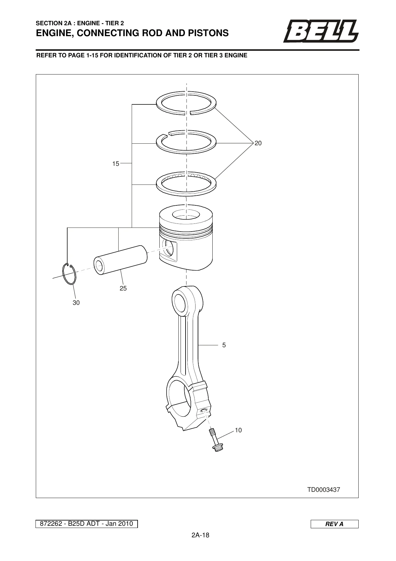
ENGINE, CONNECTING ROD AND PISTONSp. 58
ENGINE, CAMSHAFT AND TIMING PARTSp. 60
ENGINE, INJECTION PUMPp. 62
ENGINE, FUEL LINESp. 64
ENGINE, FUEL FILTERp. 66
ENGINE, FLAMESTART SYSTEMp. 68
ENGINE, TURBO CHARGERp. 70
ENGINE, AIR COMPRESSORp. 72
ENGINE, AIR COMP. ATTACHMENT PARTSp. 74
ENGINE, INTAKE MANIFOLDp. 76
ENGINE, EXHAUST MANIFOLDp. 78
ENGINE, ELECTRICAL EQUIPMENTp. 80
ENGINE, STARTING MOTORp. 82
ENGINE, ALTERNATOR AND ATTACHMENTp. 84
ENGINE, OIL PUMPp. 86
ENGINE, OIL FILTER AND OIL COOLERp. 88
ENGINE, OIL LINESp. 90
ENGINE, WATER PUMPp. 92
ENGINE, FANp. 94
ENGINE MOUNTINGSp. 96
ENGINE, AIRCONDITIONER COMPRESSORp. 98
EXHAUST SYSTEMp. 100
KIT, BIN HEATING (OPTIONAL)p. 102
AIR INTAKE SYSTEMp. 104
PRE-CLEANERp. 106
AIR CLEANERp. 108
FUEL SYSTEMp. 110
FUEL-WATER FILTER UNITp. 112
HANDLIFT PUMP & PRE-FILTERp. 114
ENGINE COOLING SYSTEM : DETAIL Ap. 116
ENGINE COOLING SYSTEM : DETAIL Bp. 118
ENGINE COOLING SYSTEM, RADIATORp. 120
SECTION 2B : ENGINE TIER 3p. 123
ENGINE, MISCELLANEOUS ITEMSp. 124
ENGINE, CRANKCASEp. 126
ENGINE, TIMING COVERp. 128
ENGINE, OIL PAN AND DIPSTICKp. 130
ENGINE, CYLINDER HEAD AND VALVESp. 132
ENGINE, CYLINDER HEAD, ROCKER ARMp. 134
ENGINE, CYLINDER HEAD COVERp. 136
ENGINE, CRANKSHAFT AND FLYWHEELp. 138
ENGINE, CONNECTING ROD AND PISTONSp. 140
ENGINE, CAMSHAFT AND TIMING PARTSp. 142
ENGINE, INJECTION PUMPp. 144
ENGINE, FUEL LINESp. 146
ENGINE, FUEL FILTERp. 148
ENGINE, FLAMESTART SYSTEMp. 150
ENGINE, TURBO CHARGERp. 152
ENGINE, AIR COMPRESSORp. 154
ENGINE, AIR COMP. ATTACHMENT PARTSp. 156
ENGINE, INTAKE MANIFOLDp. 158
ENGINE, EXHAUST MANIFOLDp. 160
ENGINE, ELECTRICAL EQUIPMENTp. 162
ENGINE, STARTING MOTORp. 164
ENGINE, ALTERNATOR AND ATTACHMENTp. 166
ENGINE, OIL PUMPp. 168
ENGINE, OIL FILTER AND OIL COOLERp. 170
ENGINE, OIL LINESp. 172
ENGINE, WATER PUMPp. 174
ENGINE, FANp. 176
ENGINE MOUNTINGSp. 178
ENGINE, AIRCONDITIONER COMPRESSORp. 180
EXHAUST SYSTEMp. 182
KIT, BIN HEATING (OPTIONAL)p. 184
AIR INTAKE SYSTEMp. 186
PRE-CLEANER ASSEMBLYp. 188
AIR-CLEANER ASSEMBLYp. 190
FUEL SYSTEMp. 192
FUEL-WATER FILTER UNITp. 194
HANDLIFT PUMP & PRE-FILTERp. 196
ENGINE COOLING SYSTEM : DETAIL Ap. 198
ENGINE COOLING SYSTEM : DETAIL Bp. 200
ENGINE COOLING SYSTEM, RADIATORp. 202
SECTION 3 : DRIVETRAINp. 205
TRANSMISSION MISC. PARTSp. 206
TRANSMISSION HOUSINGp. 208
OIL SUPPLY, CONTROL INSERTp. 210
OIL SUPPLY, CONTROL INSERT (CONTINUED)p. 212
OIL SUPPLY, COVER PLATEp. 214
RETARDER VALVEp. 216
GEARBOX PLANETARYp. 218
COUPLINGp. 220
BRAKE – SECTION Dp. 222
BRAKE – SECTION Ep. 224
BRAKE – SECTION Fp. 226
BRAKE – SECTION Gp. 228
OUTPUTp. 230
OUTPUT (CONTINUED)p. 232
SHIFT CONTROLp. 234
SHIFT CONTROL (CONTINUED)p. 236
SHIFT CONTROL, VALVE BLOCK Ap. 238
SHIFT CONTROL, VALVE BLOCK Bp. 240
SHIFT CONTROL, THROTTLE VALVEp. 242
TRANSMISSION DIPSTICKp. 244
TRANSMISSION OIL SUMPp. 246
TORQUE CONVERTERp. 248
POWER TAKE OFFp. 250
HEAT EXCHANGERp. 252
PERIPHERALSp. 254
TRANSMISSION COOLING SYSTEMp. 256
DROPBOX MISCELLANEOUS PARTSp. 258
DROP BOX MOUNTINGSp. 260
DROP BOX HOUSINGp. 262
DROP BOX INPUT SHAFTp. 264
DROP BOX IDLERp. 266
DROP BOX OUTPUT SHAFT REARp. 268
DROP BOX OUTPUT SHAFT FRONTp. 270
PARK BRAKEp. 272
PARK BRAKE ASSEMBLYp. 274
PARK BRAKE ASSEMBLY (CONTINUED)p. 276
ACTUATOR ASSEMBLYp. 278
PROPSHAFTSp. 280
AXLE, FRONTp. 282
FRONT DIFFERENTIAL ASSEMBLYp. 284
FRONT DIFF, CLUTCH CONFIGURATIONp. 286
THRU DRIVE AND OSCILLATION JOINTp. 288
SHAFT, OSCILLATION THRU DRIVEp. 290
AXLE, MIDDLEp. 292
MIDDLE DIFFERENTIAL ASSEMBLYp. 294
MIDDLE DIFFERENTIAL ASSEMBLY (CONT’D)p. 296
MIDDLE DIFFERENTIAL ASSEMBLY (CONT’D)p. 298
MIDDLE DIFF, CLUTCH CONFIGURATIONp. 300
AXLE, REARp. 302
AXLE DRAIN & FILLER PLUGSp. 304
REAR DIFFERENTIAL ASSEMBLYp. 306
REAR DIFF, CLUTCH CONFIGURATIONp. 308
BRAKE ASSEMBLYp. 310
PLANETARY HUBp. 312
WHEEL SET (CHOICE)p. 314
WHEEL SET (CHOICE) CONTINUEDp. 316
SECTION 4 : HYDRAULICSp. 319
HYDRAULIC SYSTEM, CAB – DETAIL Ap. 320
HYDRAULIC SYSTEM, CAB – DETAIL Bp. 322
BRAKE PEDALp. 324
STEERING CONTROL VALVEp. 326
EMERGENCY STEERING PUMP CHECK VALVEp. 328
PUMP, EMERGENCY STEERINGp. 330
PUMP, EMERGENCY STEERING (ALTERNATE)p. 332
PUMP, EMERG. STEER BI-DIRECTIONAL (OPTIONAL)p. 334
HYDRAULIC KIT: CAB TILT SYSTEMp. 336
CAB TILT CYLINDER BREAKDOWNp. 338
PUMP, CAB TILTp. 340
VOAC BLOCKp. 342
VOAC BLOCK – VALVE POSITIONSp. 344
VOAC BLOCK – VALVESp. 346
VOAC BLOCK – TIP SECTIONp. 348
STEERING CYLINDERSp. 350
FRONT CHASSISp. 352
MAIN PUMP DELIVERYp. 354
DAMPER ASSEMBLYp. 356
ACCUMULATOR KIT – SOUTH AFRICAp. 358
ACCUMULATOR KIT – EUROPEp. 360
HYDRAULIC PUMPp. 362
HYDRAULIC PUMP (ALTERNATIVE)p. 364
STEERING CYLINDER ASSEMBLYp. 366
HYDRAULIC TANK MISC PARTSp. 368
HYDRAULIC SYSTEM, REAR CHASSISp. 370
TIP CYLINDER BREAKDOWNp. 372
TIP CYLINDER BREAKDOWNp. 374
SECTION 5 : PNEUMATICSp. 377
PNEUMATIC KIT, CABp. 378
KIT, AIR HORN (OPTIONAL)p. 380
PNEUMATIC BLOCK ASSEMBLYp. 382
PNEUMATIC SYSTEM, FRONT CHASSISp. 384
PURGE TANK VALVEp. 386
KIT, AIR DRIERp. 388
KIT, REPAIR, AIR DRIERp. 390
KIT, 10L RESERVOIRp. 392
PNEUMATIC KIT : REAR CHASSISp. 394
SECTION 6 : ELECTRICALp. 397
CAB HARNESS – DETAIL Ap. 398
CAB HARNESS – DETAIL Bp. 400
CAB HARNESS – DETAIL Cp. 402
CAB, FUSE AND RELAY PANEL COMPONENTSp. 404
CAB, WINDSCREEN WIPER KITp. 406
CAB, TRANSMISSION HARNESSp. 408
CAB, REAR VIEW MIRROR ELECTRICAL KIT (CHOICE)p. 410
CAB, REAR VIEW MIRRORSp. 412
CAB, LOAD LIGHTS (OPTIONAL)p. 414
CAB, BEACON (OPTIONAL)p. 416
CAB, WORK LIGHTS (OPTIONAL)p. 418
CAB, REAR FACING WORK LIGHT (OPTIONAL)p. 420
CAB, MEMORY MODULEp. 422
CAB, SATELLITEp. 424
CAB, RADIO (OPTIONAL)p. 426
CAB, REAR CAMERA (OPTIONAL)p. 428
CAB, REVERSE MONITOR (OPTIONAL)p. 430
CAB, EMERGENCY BRAKE (OPTIONAL)p. 432
ENGINE HARNESSp. 434
LIGHT BREAKDOWNSp. 436
ARTIC HARNESSp. 438
BATTERY BOXp. 440
FRONT CHASSIS, TRANSMISSIONp. 442
FUEL HEATER (OPTIONAL)p. 444
HEAD LIGHT GRILLES (OPTIONAL)p. 446
REAR HARNESSp. 448
OBW SYSTEMp. 450
STRAIN GAUGE KITp. 452
CONNECTORS (SHEET 1 OF 8)p. 454
CONNECTORS (SHEET 2 OF 8)p. 456
CONNECTORS (SHEET 3 OF 8)p. 458
CONNECTORS (SHEET 4 OF 8)p. 460
CONNECTORS (SHEET 5 OF 8)p. 462
CONNECTORS (SHEET 6 OF 8)p. 464
CONNECTORS (SHEET 7 OF 8)p. 466
CONNECTORS (SHEET 8 OF 8)p. 468
SECTION 7 : FRAME & BODYp. 471
CAB ASSEMBLYp. 472
CAB SHELLp. 474
CAB / BONNET INTERFACE SEALp. 476
HVAC SEALING, CABp. 478
WINDOW GUARD, HANDRAILS & CAB MOUNTINGSp. 480
REAR VIEW MIRROR BRACKETSp. 482
CAB DOOR ASSEMBLYp. 484
CAB WINDOWSp. 486
WINDOW CATCHESp. 488
DOOR, HVAC SYSTEMp. 490
CAB INTERIOR MISC. PARTSp. 492
CAB INTERIOR HATCHES AND LIDSp. 494
CAB FLOOR MAT & INTERIOR PANELSp. 496
ROOF HEADLINERSp. 498
OPERATOR AND TRAINER SEAT INSTALLATIONp. 500
TRAINER SEAT MOUNTINGp. 502
SEATS INSTALLATION, SEARSp. 504
SEATS INSTALLATION, SEARS HIGH BACKp. 506
BASE, SEAT ASSEMBLY, SEARSp. 508
STEERING COLUMN MISCELLANEOUS PARTSp. 510
STEERING COLUMNp. 512
CAB SOUND FOAMp. 514
CAB AIR DUCTING, HVAC SYSTEMp. 516
AIRCON DRIER UNIT AND PIPINGp. 518
AIRCONDITIONER UNIT BREAKDOWNp. 520
AIRCON SYSTEM: FRONT CHASSISp. 522
HYDRAULIC TANK MISC. PARTSp. 524
HYDRAULIC TANK FILTER ASSEMBLYp. 526
FRONT CHASSIS KITp. 528
BONNET KIT: DETAIL Ap. 530
BONNET KIT: DETAIL A (CONTINUED)p. 532
BONNET KIT: DETAIL Bp. 534
BONNET CATCHp. 536
GRILLp. 538
BELLY PLATEp. 540
MUDGUARDS AND MISCELLANEOUS PARTSp. 542
BATTERY BOX KITp. 544
FUEL TANK MISC PARTSp. 546
CAP, DIESEL FILLERp. 548
COVER, HEADLIGHTp. 550
FRONT SUSPENSIONp. 552
LINK ASSEMBLY, FRONT SUSPENSIONp. 554
SPHERICAL BEARING BREAKDOWNp. 556
CYLINDER, SUSPENSION STRUTp. 558
ARTIC JOINT BEARING ASSEMBLYp. 560
REAR CHASSIS KIT : DETAIL Ap. 562
REAR CHASSIS KIT : DETAIL Bp. 564
REAR SUSPENSION : DETAIL Ap. 566
REAR SUSPENSION : DETAIL Bp. 568
BIN, RIBLESS, MISCELLANEOUS PARTSp. 570
BIN PIVOTp. 572
LINER KIT, BIN, RIBLESSp. 574
KIT, TAILGATE, BINp. 576
DECALS AND SERIAL PLATES (SHEETS 1 OF 3)p. 578
DECALS AND SERIAL PLATES (SHEETS 2 OF 3)p. 580
DECALS AND SERIAL PLATES (SHEETS 3 OF 3)p. 582
SECTION 8 : SERVICE KITSp. 585
SERVICE KITSp. 586
SERVICE KITS (CONTINUED)p. 588
SERVICE KITS (CONTINUED)p. 590
SECTION 9 :RECOMMENDED LUBRICANTS,ADHESIVES AND PAINTSp. 593
LUBRICANTSp. 594
ADHESIVESp. 595
PAINTS AND PROCEDURESp. 596
SECTION 10 : SPECIAL TOOLSp. 597
ENGINE – SERVICE TOOLSp. 598
ENGINE – SERVICE TOOLS (CONTINUED)p. 600
ENGINE – REPAIR TOOLSp. 602
ENGINE – REPAIR TOOLS (CONTINUED)p. 604
ENGINE – REPAIR TOOLS (CONTINUED)p. 606
GEAR RATIO 13100 TRANSFER CASEp. 608
GEAR RATIO 13100 TRANSFER CASE (CONTINUED)p. 610
ZF 6HP 592 C TRANSMISSIONp. 612
ZF 6HP 592 C TRANSMISSION (CONTINUED)p. 614
ZF 6HP 592 C TRANSMISSION (CONTINUED)p. 616
ZF 6HP 592 C TRANSMISSION (CONTINUED)p. 618
AXLES, DIFFS & FINAL DRIVES : REPAIR/OVERHAULp. 620
ZF HK 3.18 LS DIFFERENTIALp. 622
SUSPENSION : REPAIR/OVERHAULp. 624
HYDRAULICS : REPAIR/OVERHAULp. 626
FRAME & OSCILLATION TOOLSp. 628
DIAGNOSTIC TOOLS (DRIVELINE)p. 630
TYRE INFLATION KIT – (OPTIONAL)p. 632
SECTION 11 : NUMERICAL INDEXp. 635

Get Your Bell B25D Mk 6.1 ADT Parts Manual Instantly

IMAGES PREVIEW

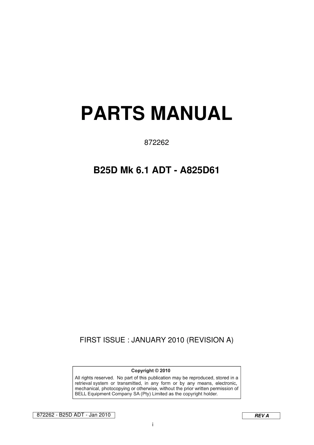
Bell B25D Mk 6.1 ADT Parts Manual 2010 - A825D61 Rev A PDF β€” PDF page 1 preview
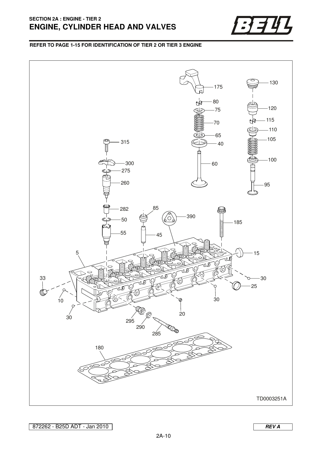
Bell B25D Mk 6.1 ADT Parts Manual 2010 - A825D61 Rev A PDF β€” PDF page 50 preview
Bell B25D Mk 6.1 ADT Parts Manual 2010 - A825D61 Rev A PDF β€” PDF page 58 preview

Whether you are rebuilding an OM906LA cylinder head, chasing a hydraulic leak in the cab tilt circuit, replacing a VOAC block valve, servicing the ZF 6HP 592 C transmission, refreshing a planetary hub, or simply replenishing the filters and seals called out in the 100 HR to 4000 HR service kits, this Bell B25D Mk 6.1 ADT parts manual gives you the correct part number, the correct quantity and the correct drawing for the job in front of you. The document is supplied as an instant-download PDF that arrives as soon as payment clears – no shipping, no waiting for a physical book to arrive, and no restriction on where you open it. Print the pages you need for the workshop, flick through them on a laptop in the cab, or keep the whole manual on a tablet for quick part lookups at the counter. Everything in this January 2010 Revision A parts manual for the A825D61 machine is there for you the moment you need it.

Reviews

There are no reviews yet.

Be the first to review “Bell B25D Mk 6.1 ADT Parts Manual 2010 – A825D61 Rev A PDF”

What Our Customers Say

β˜…β˜…β˜…β˜…β˜… Live reviews from customers
Loading customer reviews...
0
    0
    Your Cart
    Your cart is emptyReturn to Shop
    πŸ›’
    Recently Purchased
    πŸ•’ verified order