
Bell Equipment 2806D 4X4 Extended Chassis 5th Wheeler Hauler Parts Manual – June 2009 PDF
Original price was: $39.95.$23.95Current price is: $23.95.
Illustrated parts manual for the Bell Equipment 2806D 4X4 Extended Chassis 5th Wheeler Hauler, document 872249 Rev 0 (June 2009). Covers Tier 2 and Tier 3 engine sections, drivetrain, hydraulics, pneumatics, electrical, frame and body, service kits and special tools across 633 pages of exploded views and itemised part numbers.
Description
Bell Equipment 2806D 4X4 Extended Chassis 5th Wheeler Hauler Parts Manual (Document 872249)
Complete illustrated parts manual for the Bell Equipment 2806D 4X4 Extended Chassis 5th Wheeler Hauler, published as document number 872249 at Revision 0 in June 2009. This is the factory parts reference used to identify, order and replace every major assembly and component on the 2806D 4X4 extended chassis 5th wheel hauler. It covers both the Tier 2 and Tier 3 engine configurations, with a separate engine section for each.
File Details
- Manual type: Illustrated Parts Manual (Parts Catalog)
- Brand: Bell Equipment
- Model: 2806D 4X4 Extended Chassis 5th Wheeler Hauler
- Document number: 872249
- Issue / revision: First issue June 2009, Rev 0
- Language: English
- Format: PDF (printable, works on any device)
- Page count: 633 pages
Chapters Covered
- Section 1: General Information
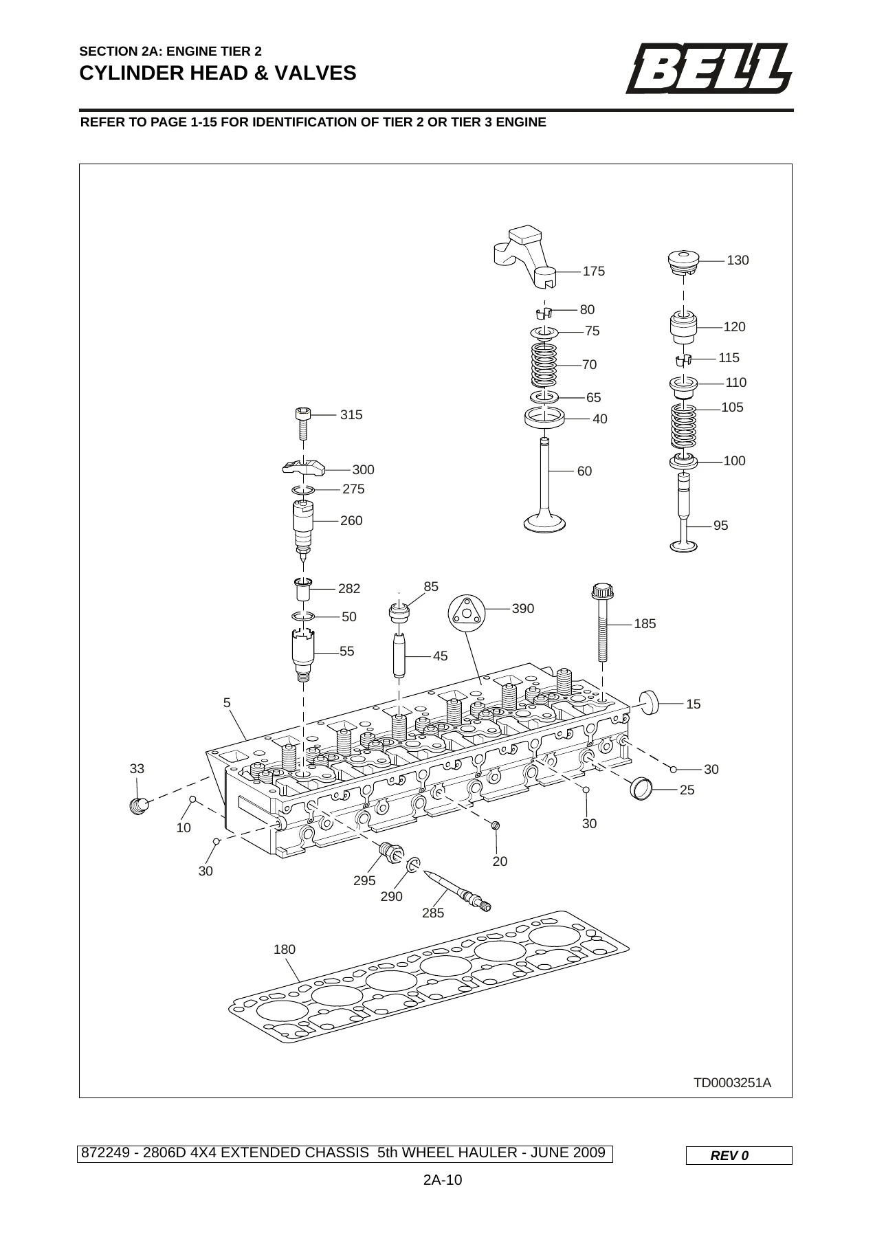
- Section 2A: Engine Tier 2 – engine and miscellaneous items, crankcase, timing cover, oil pan and dipstick, cylinder head and valves, cylinder head rocker arm, cylinder head cover, crankshaft and flywheel, connecting rod and pistons, camshaft and timing parts, injection pump, fuel lines, fuel filter, flamestart system, turbo charger, air compressor, intake manifold, exhaust manifold, electrical equipment, starter motor, alternator, oil pump, oil filter and oil cooler, oil lines, water pump, fan, engine mountings, air conditioner compressor, cooling system (Details A and B, radiator), fuel system, handlift pump and pre-filter, fuel-water filter unit, exhaust system, air intake system, air cleaner
- Section 2B: Engine Tier 3 – same structure as 2A for the Tier 3 engine
- Section 3: Drivetrain – transmission misc. parts, transmission housing, oil supply / control insert, cover plate, retarder valve, gearbox planetary, coupling, brake sections D through G, output, shift control, shift control valve blocks A and B, throttle valve, transmission dipstick, oil sump, torque converter, power take off, heat exchanger, peripherals, transmission cooling system, dropbox (miscellaneous parts, mountings, housing, input shaft, idler, output shaft rear, output shaft front), propshafts, driveline, thru drive and oscillation joint, park brake mounting, park brake assembly, actuator assembly, axle front, axle rear, axle drain and filler plugs, final drive, disc brake kit front axle, disc brake rear axle, disc brake caliper location, disc brake caliper breakdown, front and rear diff assembly, middle diff assembly, wheelset options
- Section 4: Hydraulics – VOAC block, valve positions, valve positions (high pressure), valves, end section, pumps and delivery, hydraulic pump A10V, hydraulic pump alternative, emergency steering pump check valve, emergency steering pump, main pump delivery, damper, steering cylinders, steering cylinder assembly, accumulators (South Africa and Europe), cab Details A and B, steering control valve Eaton, brake pedal, cab tilt system, cab tilt cylinder breakdown, cab tilt pump, hydraulic tank misc. parts Details A and B, cab door misc. parts, tank filter assembly, kit cooler Choices A and B, rear chassis hoses and fittings
- Section 5: Pneumatics – front chassis system, purge tank valve, 10L reservoirs, air dryer kit, air dryer repair kit, cab, kit cab, pneumatic block assembly (top and bottom views), air horn (optional), rear chassis, spillover kit
- Section 6: Electrical – cab Details A to C, fuse and relay panel components, windscreen wiper kit, cab transmission, rear view mirror electrical kit, rear view mirror manual kit, rear view mirrors, load lights, cab beacon, cab work lights, cab reverse lights, cab memory module, cab MT2000, cab radio, cab rear camera, cab reverse monitor, cab kit emergency brake, engine harness, kit headlight grills, light breakdowns, artic, battery box, transmission, fuel heater, batteries, rear chassis, electrical connectors (sheets 1 to 8)
- Section 7: Frame and Body – bonnet kit Details A and B, bonnet misc. parts Details A and B, cab assembly, cab shell, cab / bonnet interface seal, HVAC sealing, window guard, handrails and cab mountings, rear view mirror brackets, cab door assembly, cab windows, window catches, door HVAC system, cab interior misc. parts, cab interior hatches and lids, cab floor mats and interior panels, roof headliners, kit sound foam, steering column misc. parts, steering column, operator and trainer seat installation, trainer seat mounting, seat assembly Sears, seats installation Sears high back, base seat assembly Sears, cab airducting HVAC system, aircon drier unit and piping, aircon unit, aircon system front chassis, belly plate and misc. parts, grill and misc. parts, front chassis kit, mudguards and misc. parts, battery box and misc. parts, fuel tank misc. parts, cap diesel filler, cover headlight assembly, front suspension, tri-link spherical front suspension, suspension strut, artic joint bearing assembly, decals (sheets 1 and 2)
- Section 8: Service Kits – 100HR, 500HR, 1000HR, 2000HR, 3000HR, 4000HR and 6000HR service kits for dry and wet conditions
- Section 9: Lubricants, Adhesives and Paints
- Section 10: Special Tools – OM906LA service tools (kit 262126), repair tools (kits 262127 and 262128), gear ratio 13100 transfer case tools, axles / diffs / final drives repair and overhaul tools, suspension repair tools, hydraulics repair tools, frame and oscillation tools, diagnostic tools (driveline), tyre inflation kit
- Section 11: Numerical Index
Across its 633 pages, this Bell 2806D 4X4 Extended Chassis 5th Wheeler Hauler parts manual breaks the machine down into illustrated assemblies and itemised parts tables. Every exploded view is followed by a parts list carrying item numbers, Bell part numbers, quantities, descriptions and remarks, so a technician or parts counter can trace a component from system to subassembly to individual part number. Because the machine is split into Tier 2 (Section 2A) and Tier 3 (Section 2B) engine paths, the manual stays accurate whichever emissions specification of OM906LA engine is fitted, and it explains how to identify which one applies.
How to Identify the Correct Engine Section
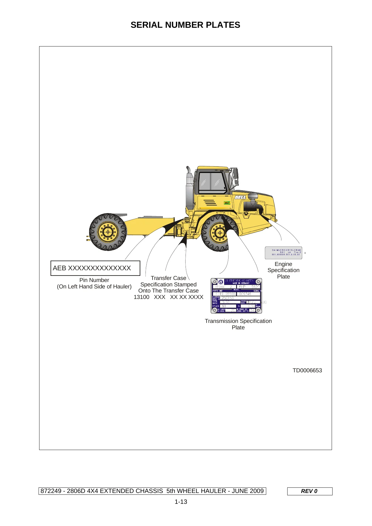
The manual explains that engine identification comes from the engine number stamped on the specification plate. An engine number beginning 906.950 indicates a Tier 2 engine; an engine number beginning 906.991 indicates a Tier 3 engine. Once you know which tier applies to your machine, you can work from the corresponding engine section (2A or 2B) for the correct part numbers. Machine serial numbers follow the Bell PIN structure beginning with the world manufacturer code AEB for South African-built units, stamped on the plate on the left-hand side of the hauler.
Systems and Assemblies Covered
The scope of this 2806D parts catalog is whole-machine rather than engine-only. Alongside both engine sections, the manual covers the ZF transmission in detail: housing, planetary gearbox, coupling, brake sections D through G, output, shift control and valve blocks, throttle valve, dipstick, oil sump, torque converter, power take off, heat exchanger and cooling. The driveline, dropbox, propshafts, oscillation joint and thru-drive are fully exploded. Front and rear axles are covered through banjo housings, final drives, planetary carriers, wheel hubs, disc brakes, calipers, and front / rear and middle differential assemblies. Wheelset options for 23.5×25 and 23.5xR25 fitments are listed.
Hydraulics span the VOAC block with its valve positions and pressure sections, service and emergency steering pumps, the A10V hydraulic pump, main pump delivery, damper, steering cylinders, accumulators for South African and European markets, the Eaton steering control valve, brake pedal, cab tilt system and the hydraulic tank.
Pneumatics cover the front chassis system, purge tank valve, 10-litre reservoirs, air dryer kit and repair kit, the cab pneumatic block in top and bottom views, optional air horn, rear chassis, and spillover kit.
Electrical documentation is unusually thorough: cab Details A through C, fuse and relay panel components with the fuse and relay layout, wiper kit, transmission harness, mirror kits, load lights, beacon, work lights, reverse lights, memory module, MT2000, radio, rear camera, reverse monitor, emergency brake kit, engine harness, battery box, fuel heater, and eight sheets of electrical connector part numbers. Frame and body coverage includes the bonnet, cab shell and doors, windows and catches, HVAC system, seats, steering column, air conditioning, mudguards, fuel tank, headlight covers, front suspension and the artic joint bearing assembly, plus both sheets of decals.
Section 8 provides service kits grouped by hour interval (100HR through 6000HR) for dry and wet operating conditions. Section 9 lists recommended lubricants, adhesives and paint procedures. Section 10 details the special tools required for OM906LA engine work, the 13100 transfer case, axles, diffs and final drives, suspension, hydraulics, frame and oscillation, plus driveline diagnostic tools and the tyre inflation kit. Section 11 is a numerical index that lets you look up a part number directly and find the page where it appears.
Who This Manual Is For
This is a working reference for anyone who maintains, repairs or restores a Bell 2806D 4X4 extended chassis 5th wheel hauler: workshop technicians, fleet maintenance planners, parts interpreters, and owners who prefer to order the right part number the first time. Because every section ends with an itemised parts list tied to its illustration, the manual is equally useful for a quick gasket or filter lookup and for a full subassembly overhaul.
Why the Part Number Detail Matters
On a machine like the 2806D, many components look similar across engine tiers, axle positions and market variants. Accumulators differ between South Africa and Europe, disc brake kits differ front to rear, and the engine section splits between Tier 2 and Tier 3. Ordering from the wrong section wastes time and money. This Bell Equipment 2806D 4X4 5th wheel hauler parts manual removes the guesswork by tying every part number to a specific illustration, item number, quantity and, where relevant, a remark explaining fitment or an alternative part.
IMAGES PREVIEW
Delivery: This Bell Equipment 2806D 4X4 Extended Chassis 5th Wheeler Hauler parts manual is supplied as an instant PDF download after checkout. There is no shipping, no waiting, and no physical book to lose. Read it on a laptop or tablet in the workshop, print the pages you need for the job at hand, or keep the whole 633-page document on file for future maintenance. It works on any device that opens a PDF.
Reviews
There are no reviews yet.