
Bell OH-58A/C Scout Helicopter Operator’s Manual TM 55-1520-228-10 PDF
Original price was: $27.95.$16.95Current price is: $16.95.
Army TM 55-1520-228-10 operator’s manual for the OH-58A/C observation helicopter with T63-A-720 engine. Covers systems, limits, weight and balance, performance charts, normal procedures, and emergencies through Change 11.
Description
File Details
- Manual type: Operator’s Manual (Technical Manual)
- Brand / model: Army Model OH-58A and OH-58C helicopter
- Document number: TM 55-1520-228-10
- Original date: 17 January 1989
- Latest change in this file: Change 11, 1 April 2003
- Supersedes: TM 55-1520-228-10 and TM 55-1520-236-10, 7 April 1978
- Language: English
- Page count: 275 PDF pages (publication lists 265 pages plus change sheets)
- File format: PDF
- Distribution: Distribution Statement A — approved for public release
What This Operator’s Manual Contains
The Bell OH-58A/C Scout Helicopter Operator’s Manual TM 55-1520-228-10 PDF is the Army operator’s technical manual written for flight crews of the single-engine observation helicopter. Headquarters, Department of the Army first published TM 55-1520-228-10 on 17 January 1989. This file includes the change record through Change 11 dated 1 April 2003. The text states that the book is required to be carried in the helicopter at all times.
Both series are treated together. Designator symbols mark material that applies only to the OH-58A or only to the OH-58C. A note in Chapter 1 states that all OH-58A and OH-58C aircraft covered by this issue are equipped with the T63-A-720 turbine engine. Older T63-A-700 performance charts have been deleted. Armament and mission-equipment chapters are marked not applicable; those pages and figures have been removed.
Use this book for cockpit and systems knowledge, servicing on the line, weight and balance, performance planning, checklist-style normal procedures, and emergency actions. It is not a depot maintenance or overhaul manual.
Airframe, Crew Stations, and Landing Gear
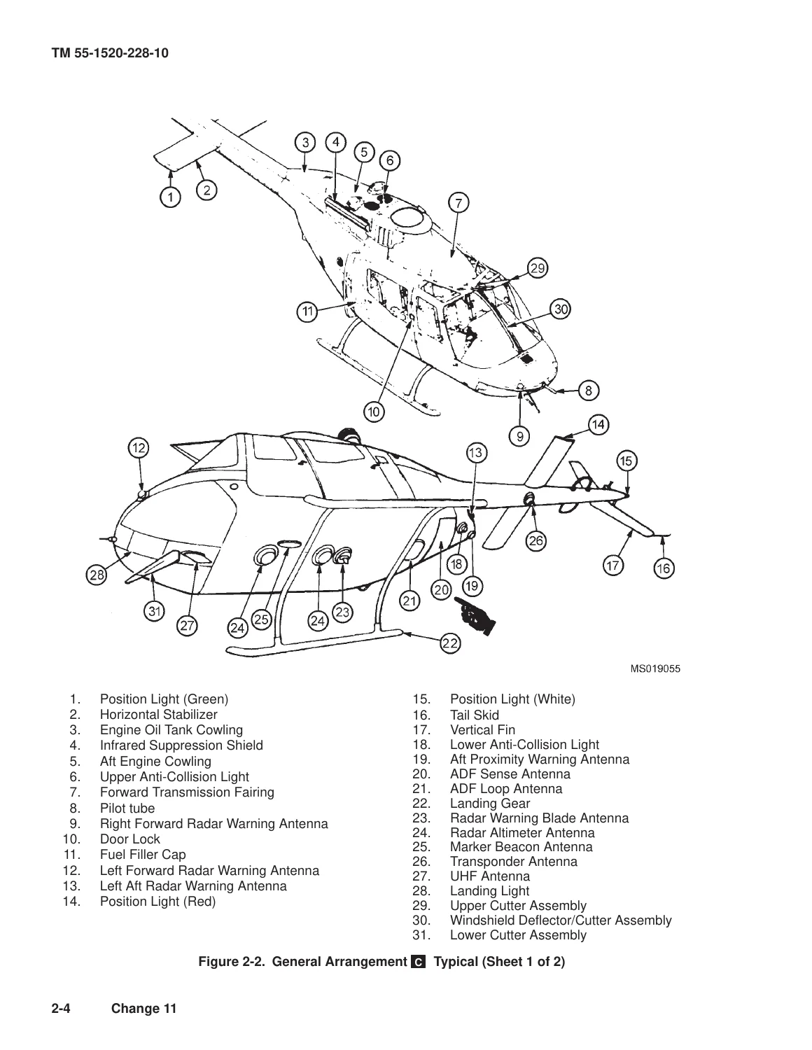
Chapter 2 describes a three-section fuselage: forward cabin and fuel-cell enclosure, intermediate engine and equipment section, and monocoque tailboom. The pilot sits on the right; the copilot or observer sits on the left. The area aft of those seats is the cargo and passenger compartment. Two doors on each side give cabin access. Removable ceramic and fiberglass armor, with a small amount of dual-hardness steel, protects the seat bottom, seat back, and outboard side of each crew seat.
Standard landing gear is a skid type with arched crosstubes, formed aluminum skid tubes, and steel shoes. High-skid gear adds about 14 inches of height. Float gear is also documented for the A-model arrangement. Ground-handling wheels are manually retractable and removable. Figure 2-5 lists principal dimensions for standard skid, high skid, and float gear, including a main-rotor diameter of 35 ft 4.0 in, tail-rotor diameter of 5 ft 2.0 in, and overall length of 40 ft 11.8 in from the main rotor (fore and aft) to the aft end of the tail skid.
T63-A-720 Engine and Related Systems
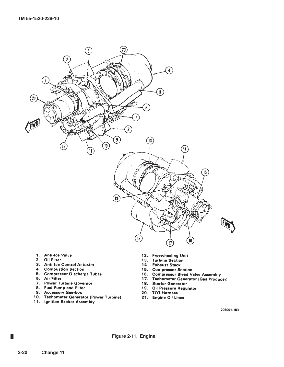
The helicopter uses one T63-A-720 turbine installed aft of the mast and passenger compartment. Air reaches the compressor through a particle separator (six axial stages plus one centrifugal stage). A two-stage gas-producer turbine drives the compressor and N1 accessory train. A two-stage power turbine supplies output power through a two-stage helical and spur reduction set. Accessories on the N2 train include the power-turbine tachometer-generator, power-turbine governor, and torquemeter. The N1 train drives the fuel pump, gas-producer tachometer-generator, fuel control, starter-generator, and engine oil pump.
Related systems in the same chapter include compartment cooling, the induction system with optional reverse-flow inlet fairings for snow, compressor-bleed inlet anti-ice (ENG DEICE), the power-turbine governor and throttle/idle-stop arrangement, engine instruments (torquemeter, TOT, N1, dual tachometer, oil pressure and temperature), chip detectors, and the ENG OIL BYPASS caution circuit. The automatic relight system is listed as not used and not functional.
Fuel, Flight Controls, and Airframe Systems
The fuel system is a self-sealing crashworthy cell under and aft of the passenger seat, with self-sealing lines, boost pump, quantity and low-fuel transmitters, sump drain, manual shutoff on the overhead console, and closed-circuit refueling on crashworthy aircraft. Table 2-1 lists main-tank capacity as 71.5 U.S. gal (70.3 usable) for JP-4, JP-5, JP-8, or emergency aviation gasoline without TCP. An optional auxiliary cell in the passenger compartment holds 23.9 U.S. gal and feeds the main cell by gravity only. An airframe-mounted 10-micron fuel filter (after MWO 1-1520-228-50-48) includes a FUEL FILTER caution for impending bypass. The cockpit fuel quantity indicator reads 0 to 600 pounds.
Later Chapter 2 sections cover flight controls, the hydraulic system, power train, main and tail rotor groups, utility systems, heating and ventilation, the 28 Vdc electrical supply and distribution schematic, lighting, flight instruments, and servicing, parking, and mooring. Servicing diagrams locate filler caps and sight glasses for engine oil, transmission oil, tail-rotor gearbox oil, and hydraulic fluid. Engine oil capacity is 11.2 U.S. pt; transmission oil is 4.0 U.S. qt. Approved oils include MIL-L-7808 for cold ambient temperatures and MIL-L-23699 (or DOD-L-85734 as a replacement for MIL-L-23699) for warmer conditions. Hydraulic fluid is MIL-H-5606 or MIL-H-83282, filled to the reservoir overfill lip.
Avionics
Chapter 3 covers communications, navigation, transponder and radar, and the SINCGARS AN/ARC-201 radio set. Illustrated controls include C-6533/ARC, AN/ARC-114 and 114A, AN/ARC-115, AN/ARC-116, AN/ARC-164 UHF/AM sets, TSEC/KY-58 voice security, AN/ARN-89 ADF, CONUS navigation receiver and CDI on C-model aircraft, APX-72 and C-model transponder panels, radar altimeter, AN/APR-39A(V)1 radar signal detecting set, and the AN/ARC-201 control panel with zeroize switch. Antenna locations are shown in Figure 3-1. Chapter 4 mission avionics and armament are not applicable in this change level.
Chapters Covered
- Chapter 1 Introduction — warnings/cautions/notes, designation system, designator symbols A and C, shall/should/may
- Chapter 2 Helicopter and Systems Description and Operation — helicopter structure and landing gear; emergency equipment; engines and related systems; fuel system; flight controls; hydraulic system; power train; main and tail rotor groups; utility system; heating and ventilation; electrical power supply and distribution; lighting; flight instruments; servicing, parking, and mooring
- Chapter 3 Avionics — communications; navigation; transponder and radar; SINCGARS AN/ARC-201
- Chapter 4 Mission Equipment — mission avionics and armament not applicable (pages deleted)
- Chapter 5 Operating Limits and Restrictions — general; systems limits; power limits; load limits; airspeed limits; maneuvering; environmental restrictions
- Chapter 6 Weight/Balance and Loading — general; DD Form 365
- Chapter 7 Performance Data — introduction; temperature conversion; torque available C; hover; cruise; drag C; climb–descent; idle fuel flow (A-model performance sections deleted)
- Chapter 8 Normal Procedures — mission planning; operating procedures and maneuvers; instrument flight; flight characteristics; adverse environmental conditions
- Chapter 9 Emergency Procedures — helicopter systems; mission equipment not applicable
- Appendix A References
- Alphabetical Index
Taken as a whole, the Bell OH-58A/C Scout Helicopter Operator’s Manual TM 55-1520-228-10 PDF gives the crew a single reference for how the observation helicopter is built and flown, what the instruments and caution panels mean, how to service fluids and moor the aircraft, how to stay inside published limits, and how to plan hover, cruise, and climb performance with the T63-A-720 engine.
Operating Limits That Drive Daily Flying
Chapter 5 collects the limits that must be observed on the ground and in flight. Maximum gross weight is 3200 pounds. Towing is limited to 3000 pounds. Minimum crew is the pilot in the right seat. Airspeed markings show 0 to 120 knots normal with 120 knots IAS maximum; recommended maximum IAS for autorotation is 100 knots. Sideward flight is limited to 35 knots and rearward flight to 30 knots. Any door removed drops maximum indicated airspeed to 100 knots. Doors shall not be opened in flight, and the helicopter will not be flown without cabin doors unless the specified rear electronics soundproof blanket is installed.
Engine oil pressure minimum is 50 PSI, with N1-dependent green bands up to 130 PSI maximum (150 PSI may appear on a cold start at idle only). Engine oil temperature normal range is 0°C to 107°C, with cold-weather operation permitted down to −50°C oil temperature. Transmission oil temperature warning is 110°C; transmission oil pressure warning is 30 ± 2 PSI minimum. Rotor tachometer normal band is 93 to 110 percent. Engine tachometer normal band is 98 to 100 percent with 100 percent maximum and a 15-second 110 percent N2 transient in autorotation. Torquemeter normal is 0 to 85 percent, 85 to 100 percent for 5 minutes, and 100 percent maximum. TOT limits cover start (0°C to 810°C normal; 927°C for 1 second) and continuous operation (300°C to 738°C normal; 810°C maximum with short transients defined on the instrument marking figure).
Start wind limit is 45 knots with a 15-knot gust spread. Hover wind limits are 35 knots crosswind and 30 knots tailwind. Mooring wind limit is 65 knots. JP-4 has no special fuel restriction. JP-5, JP-8, Jet A, and Jet A-1 are restricted to ambient temperatures of −32°C (−25°F) and above and require a deceleration check. Emergency aviation gasoline is limited to 6 hours accumulated use, and practice autorotation is prohibited on that fuel. Engine starting is aborted if N1 does not reach 58 percent in 45 seconds (60 seconds below 10°C FAT). The Health Indicator Test (HIT) compares observed TOT with a baseline at a selected N1; a ±20°C difference is logged for maintenance, and ±40°C is a grounding limit.
Weight and Balance and Performance Planning
Chapter 6 supplies the station diagram, center-of-gravity limit chart, cargo-space layout, fuel loading chart (JP-4 at 6.5 lb/gal, JP-5 at 6.8 lb/gal, plus JP-8), personnel loading, and cargo moment chart, used with DD Form 365. Chapter 7 performance data is built around the T63-A-720 and JP-4. Remaining charts include temperature conversion, 30-minute and continuous torque available, hover (including OGE examples), cruise, drag, climb–descent, and idle fuel flow. The text notes that T63-A-720 output can exceed the transmission structural limit of 100 %Q under some conditions, so torque—not raw engine capability—is the planning constraint.
Normal Procedures, Flight Characteristics, and Emergencies
Chapter 8 walks through mission planning, exterior check areas, engine start and run-up cues (starter release at 58–62% N1, oil-pressure rise, rotor turning by 30% N1), operating maneuvers, instrument flight, flight characteristics including loss of tail rotor effectiveness factors, and adverse weather. Chapter 9 covers helicopter-system emergencies, including engine malfunction with partial or complete power loss, engine overspeed, and related system failures, plus emergency-exit and equipment illustrations and autorotational glide and height-velocity information.
Use This Manual on the Line and in the Cockpit
The Bell OH-58A/C Scout Helicopter Operator’s Manual TM 55-1520-228-10 PDF supports preflight and thru-flight checks, correct fluid and fuel servicing, HIT trend recording, weight-and-balance computation, hover and cruise performance planning, observance of airspeed, torque, TOT, rotor, and wind limits, and execution of published normal and emergency procedures on the OH-58A and OH-58C with the T63-A-720 engine. Flying and servicing to the figures and limits in this TM keeps the observation helicopter inside the envelope the Army published for the type. After purchase you receive an instant PDF download — no shipping wait — that you can open on any device and print the pages you need for the cockpit bag or the line shack.
Reviews
There are no reviews yet.