UH-60A UH-60L Black Hawk Operator’s Manual TM 1-1520-237-10 – 2019 Base, Change 2
$44.95 Original price was: $44.95.$26.95Current price is: $26.95.
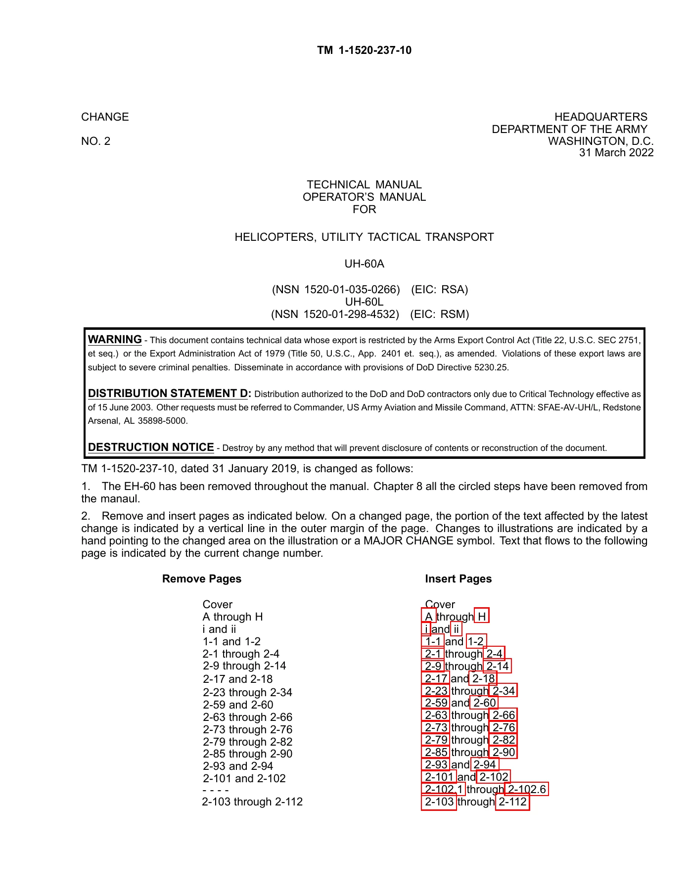
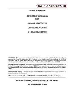
782-page PDF operator’s manual TM 1-1520-237-10 for UH-60A and UH-60L utility tactical transport helicopters. The 31 January 2019 base manual is incorporated with Change 2 dated 31 March 2022 and covers aircraft systems, T700-GE-701C and T700-GE-701D/CC engines, avionics, mission equipment, operating limits, weight and balance, performance data, normal procedures, and emergency procedures. The document carries an export-control warning and Distribution Statement D; access and use are subject to the restrictions stated in the manual.
Description
UH-60A UH-60L Black Hawk Operator’s Manual TM 1-1520-237-10 – 2019 Base, Change 2
The UH-60A and UH-60L operator’s manual is a detailed operating reference for the utility tactical transport helicopter configurations covered by TM 1-1520-237-10. The base technical manual is dated 31 January 2019 and this PDF incorporates Change 2 dated 31 March 2022. It brings together the information an operator needs to understand aircraft systems, operating restrictions, loading and performance, mission equipment, normal procedures, and emergency actions in one extensive reference.
The manual describes the UH-60A/L Black Hawk as a twin-turbine-engine, single-rotor helicopter used for tactical transport of troops, supplies, and equipment, with additional missions identified in the manual including medical evacuation, cargo, reconnaissance, training, and disaster-relief support. Propulsion coverage includes the T700-GE-701C and T700-GE-701D/CC engines, along with the fuel, lubrication, starting, engine-control, anti-ice, indication, and related systems that support their operation. The document also explains differences and designator-specific information for the UH-60A and UH-60L where applicable.
File Details
- Manual type: Operator’s Manual / Technical Manual
- Models: UH-60A and UH-60L utility tactical transport helicopters
- Document number: TM 1-1520-237-10
- Base manual date: 31 January 2019
- Change: Change 2
- Change 2 date: 31 March 2022
- Language: English
- PDF file length: 782 pages
- File format: PDF
Aircraft Systems and Operating Information
This UH-60A UH-60L Black Hawk Operator’s Manual TM 1-1520-237-10 – 2019 Base, Change 2 gives substantial system-level coverage before moving into operating limitations and procedures. The aircraft and systems chapter explains the cockpit and cabin arrangement, landing gear, doors and windows, crew and troop provisions, emergency equipment, engines, fuel system, flight controls, hydraulic and pneumatic systems, powertrain, rotor groups, utility systems, environmental-control equipment, electrical power distribution, auxiliary power unit, lighting, flight instruments, and servicing subjects.
Engine coverage goes beyond a simple description. The manual identifies the T700 engine as a modular front-drive turboshaft and explains its cold section, hot section, power turbine section, and accessory section. It covers the engine fuel supply system, hydromechanical unit, digital and enhanced digital engine controls, ignition, alternator, bleed-air and anti-icing systems, oil system, starting system, speed and torque control, instrumentation, and associated cautions and operating indications. The T700-GE-701D/CC is identified in the manual as a replacement for the T700-GE-701C on the UH-60L while retaining the performance basis described for that configuration.
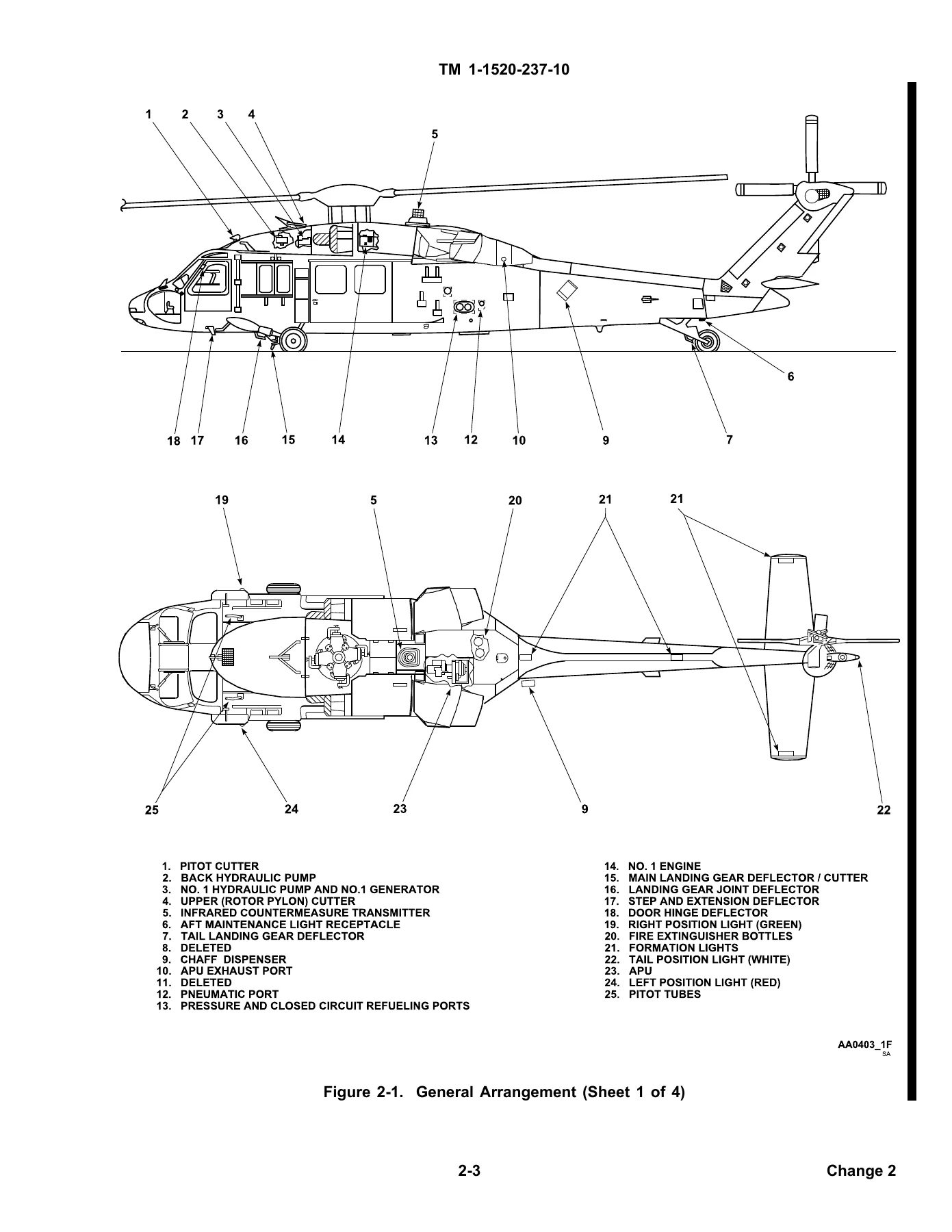
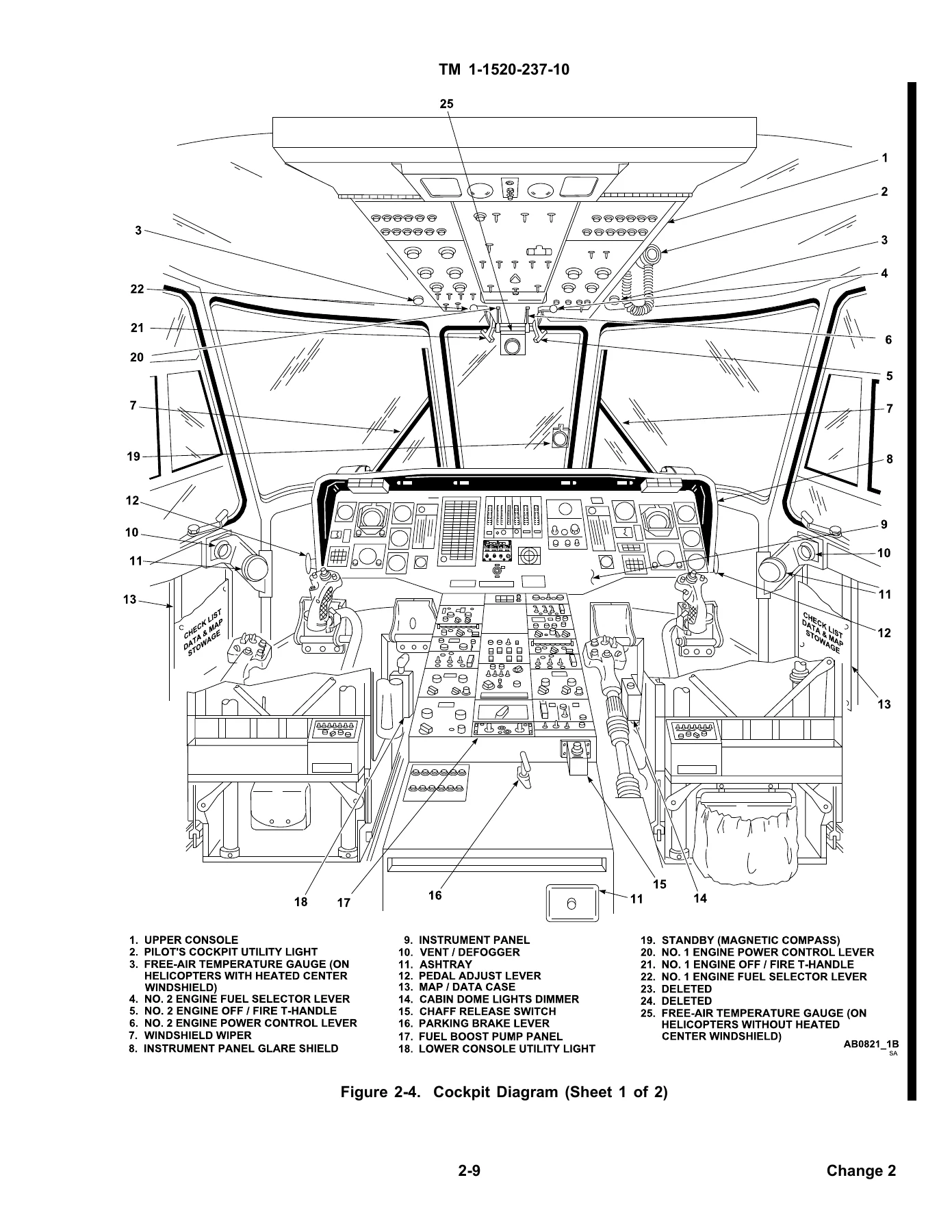
Flight-control and hydraulic information is similarly detailed. The manual describes cyclic, collective, and directional controls; mechanical mixing; pilot-assist servos; stability augmentation; trim; flight-path stabilization; the stabilator system; primary and tail-rotor servos; and the independent No. 1, No. 2, and backup hydraulic systems. System descriptions are supported throughout the manual by aircraft arrangement drawings, cockpit and console diagrams, engine illustrations, control diagrams, logic diagrams, and system schematics.
Avionics, Mission Equipment, and Crew Systems
The avionics chapter covers communication, navigation, transponder, and radar equipment, while the mission-equipment chapter addresses mission avionics, armament, cargo handling, mission-flexible systems, Air Warrior equipment, Blue Force Tracking, and the encrypted aircraft wireless intercom system. The manual also includes cockpit controls and instrument layouts, caution and advisory indications, and operating descriptions that help the reader connect individual controls with the systems they command.
Cargo and personnel information is integrated with operational planning. The manual includes troop seating and restraint provisions, cargo-loading material, mission-equipment loading, center-of-gravity information, and the weight-and-balance data needed to support aircraft loading calculations. This makes the UH-60A and UH-60L operator manual useful not only for system familiarization but also for preparing the helicopter for a specific mission configuration within the stated limits.
IMAGES PREVIEW
Operating Limits, Performance, and Procedures
Operating limits are organized into system, power, loading, airspeed, maneuvering, environmental, and other restrictions. The performance sections then provide the planning data used with those limits. Chapter 7A includes maximum torque available, hover, cruise, optimum cruise, drag, climb and descent, fuel flow, airspeed-system characteristics, and special-mission performance material. These sections are intended to support mission planning and aircraft operation using the conditions and charts supplied in the manual.
Normal procedures cover mission planning, operating procedures and maneuvers, instrument flight, flight characteristics, and adverse environmental conditions. Mission-planning material specifically ties together limits and restrictions, weight and balance, loading, performance, required publications, flight planning, and crew or passenger briefings. Emergency procedures are organized separately for aircraft systems and mission equipment, giving crews a dedicated reference for abnormal and emergency situations after the systems and normal operating logic have already been established in earlier chapters.
Chapters Covered
- Chapter 1 – Introduction
- Chapter 2 – Aircraft and Systems Description and Operation
- Section I – Aircraft
- Section II – Emergency Equipment
- Section III – Engines and Related Systems
- Section IV – Fuel System
- Section V – Flight Controls
- Section VI – Hydraulic and Pneumatic Systems
- Section VII – Powertrain System
- Section VIII – Main and Tail Rotor Groups
- Section IX – Utility Systems
- Section X – Heating, Ventilation, Cooling, and Enviromental Control Unit
- Section XI – Electrical Power Supply and Distribution System
- Section XII – Auxiliary Power Unit
- Section XIII – Lighting
- Section XIV – Flight Instruments
- Section XV – Servicing, Parking, and Mooring
- Chapter 3 – Avionics
- Section I – General
- Section II – Communications
- Section III – Navigation
- Section IV – Transponder and Radar
- Chapter 4 – Mission Equipment
- Section I – Mission Avionics
- Section II – Armament
- Section III – Cargo Handling Systems
- Section IV – Mission Flexible Systems
- Section V – Air Warrior
- Section VI – Blue Force Tracking System
- Section VII – Encrypted Aircraft Wireless Intercom System
- Chapter 5 – Operating Limits and Restrictions
- Section I – General
- Section II – System Limits
- Section III – Power Limits
- Section IV – Loading Limits
- Section V – Airspeed Limits
- Section VI – Maneuvering Limits
- Section VII – Environmental Restrictions
- Section VIII – Other Limitations
- Chapter 6 – Weight/Balance and Loading
- Section I – General
- Section II – Weight and Balance
- Section III – Fuel/Oil
- Section IV – Personnel
- Section V – Mission Equipment
- Section VI – Cargo Loading
- Section VII – Center-of-Gravity
- Chapter 7 – Performance Data
- Section I – Introduction
- Section II
- Chapter 7A – Performance Data
- Section I – Introduction
- Section II – Maximum Torque Available
- Section III – Hover
- Section IV – Cruise
- Section V – Optimum Cruise
- Section VI – Drag
- Section VII – Climb – Descent
- Section VIII – Fuel Flow
- Section IX – Airspeed System Characteristics
- Section X – Special Mission Performance
Complete PDF Bookmark TreeComplete Bookmarks
The complete bookmarks in the “UH-60A UH-60L Black Hawk Operator's Manual TM 1-1520-237-10 – 2019 Base, Change 2” are as follows:
TABLE OF CONTENTSp. 17LAST CHANGEp. 5WARNINGp. 1+CHAPTERS
CHAPTER 1. INTRODUCTIONp. 21+CHAPTER 2. AIRCRAFT AND SYSTEMS DESCRIPTION AND OPERATIONp. 23
2-15. Fire Protection Systems.p. 532-28. Engine Anti-Icing Systems.p. 602-62. Heating System.p. 962-82. Electronic Navigation Instrument Display System.p. 116+CHAPTER 3. AVIONICSp. 153
3-8. TSEC/KY-58.p. 1773-16. Doppler/GPS Navigation Set (DGNS) AN/ASN-128B.p. 1953-17. Doppler/GPS Navigation Set (DGNS) AN/ASN-128D. 128D.p. 212+CHAPTER 4. MISSION EQUIPMENTp. 305
4-7. Radar Signal Detecting Set AN/APR-39A without Laser Signal Detecting Set (AN/AVR-2B).p. 3264-19. Cargo Hook System.p. 354CHAPTER 5. OPERATING LIMITS AND RESTRICTIONSp. 417CHAPTER 6. WEIGHT/BALANCE AND LOADINGp. 441CHAPTER 7. PERFORMANCE DATAp. 479+CHAPTER 7A. PERFORMANCE DATAp. 481
7A-19. Use of Charts.p. 4977A-20. Single-Engine.p. 498+CHAPTER 8. NORMAL PROCEDURESp. 667
8-19. Cockpit Equipment Checks.p. 6728-20. Starting Engines.p. 6778-39. Cold Weather Operation.p. 688CHAPTER 9. EMERGENCY PROCEDURESp. 693+FIGURES
Figure 2-1. General Arrangement (Sheet 1 of 4)p. 25Figure 2-2. Principle Dimensionsp. 29Figure 2-3. Turning Radius and Clearancep. 30Figure 2-4. Cockpit Diagram (Sheet 1 of 2)p. 31Figure 2-5. Cabin Interior (Sheet 1 of 3)p. 33Figure 2-7. Upper Console (Sheet 1 of 3)p. 38Figure 2-8. Lower Console (Sheet 1 of 5)p. 41Figure 2-9. Instrument Panel (Sheet 1 of 5)p. 46Figure 2-10. Troop Seatsp. 53Figure 2-11. Engine T700 (Sheet 1 of 2)p. 56Figure 2-12. Signal Validation – Fault Codesp. 64Figure 2-13. Engine Control Quadrantp. 67Figure 2-14. Collective and Cyclic Grips (Sheet 1 of 2)p. 71Figure 2-15. Automatic Flight Control System (AFCS) Switch Panelp. 75Figure 2-16. Hydraulic Logic Module Operation Principle (Sheet 1 of 2)p. 82Figure 2-17. Main Rotor Blade and BIM Systemp. 87Figure 2-18. Rotor Blade De-ice Kitp. 90Figure 2-18A. Option II Cabin Heaterp. 98Figure 2-19. Electrical System (Sheet 1 of 2)p. 101Figure 2-20. DC and AC Circuit Breaker Panels (Sheet 1 of 7)p. 104Figure 2-21. Auxiliary Power Unit (APU) (Typical)p. 112Figure 2-22. Altimeter Encorder AAU-32Ap. 116Figure 2-23. Vertical Situation Indicatorp. 117Figure 2-24. Horizontal Situation Indicatorp. 119Figure 2-25. CIS Modes of Operation (Sheet 1 of 2)p. 121Figure 2-25A. Electronic Standby Instrument Systemp. 127Figure 2-25B. ESIS Menu Displayp. 129Figure 2-25C. ESIS Display Invalidp. 131Figure 2-26. Master Warning Panelp. 134Figure 2-27. Caution/Advisory Panel (Sheet 1 of 3)p. 138Figure 2-28. Servicing Diagram (Sheet 1 of 3)p. 142Figure 2-29. Mooringp. 152Figure 3-1. Antenna Arrangement (Sheet 1 of 3)p. 157Figure 3-2. Intercommunication Control Panel C-6533A/ARCp. 160Figure 3-3. VHF Control AN/ARC-186(V) (Sheet 1 of 2)p. 163Figure 3-5. FM Control AN/ARC-201p. 169Figure 3-6. UHF Control, AN/ARC-164(V)p. 173Figure 3-7. Voice Security Equipmentp. 178Figure 3-8. Remote Fill Panelp. 180Figure 3-9. Retransmission Control Panelp. 180Figure 3-10. Control Display Unit AN/ARC-220p. 185Figure 3-11. KY-100 Secure Communication Control Panelp. 189Figure 3-12. LF/ADF Control Panel C-7932/ARN-89p. 190Figure 3-13. LF/ADF Control Panel AN/ARN-149p. 192Figure 3-14. Radio Receiving Set AN/ARN-123(V)p. 193Figure 3-15. VOR/ILS/MB Control Panel AN/ARN-147(V)p. 195Figure 3-16. Doppler/GPS Navigation Set AN/ASN-128B/Dp. 197Figure 3-17. Definition of Course Termsp. 210Figure 3-18. PCMCIA Data Transfer Device and GPS Annunciator Panelp. 213Figure 3-19. Definition of Termsp. 220Figure 3-20. AN/ASN-128D Power Up Menup. 221Figure 3-21. AN/ASN-128D Power Up DAFIF Menup. 222Figure 3-22. WIND-UTC DATA Main Menup. 222Figure 3-23. WIND-UTC DATA Menu 2p. 222Figure 3-24. WIND-UTC DATA Menu 3p. 223Figure 3-25. WIND-UTC DATA STATUS Menup. 223Figure 3-26. WIND-UTC DATA LOAD Menup. 224Figure 3-27. WIND-UTC DATA USER WAYPOINTS Menup. 224Figure 3-28. WIND-UTC DATA FLIGHT PLANSp. 225Figure 3-29. WIND-UTC DATA DAFIF Menup. 225Figure 3-30. WIND-UTC DATA CONFIG Menup. 225Figure 3-31. XTK/TKE KEY Main Menup. 226Figure 3-32. XTK/TKE KEY Menu 2p. 226Figure 3-33. XTK/TKE KEY Menu 3p. 227Figure 3-34. XTK/TKE KEY Menu 4-6p. 227Figure 3-35. XTK/TKE KEY Menu 7p. 228Figure 3-36. GS/TK NAV M Main Menup. 228Figure 3-37. GS/TK NAV M Menu 2p. 228Figure 3-38. Presentation Position Main Menup. 229Figure 3-39. Presentation Position Main Menu 2p. 230Figure 3-40. DIST/BRG TIME Main Menup. 230Figure 3-41. DIST/BRG TIME Menu 2p. 231Figure 3-42. DIST/BRG TIME Menu 3p. 231Figure 3-43. WP TGT Main Menup. 232Figure 3-44. WP TGT Menu 2p. 232Figure 3-45. WP TGT Menu 2, P Onlyp. 233Figure 3-46. DATUM ROUTE Main Menu, Page 1p. 233Figure 3-47. DATUM ROUTE Main Menu, Page 2p. 233Figure 3-48. DATUM PAGE Menup. 234Figure 3-49. DATUM ROUTE FP Main Menup. 234Figure 3-50. DATUM ROUTE FP Menu 2p. 235Figure 3-51. DATUM ROUTE FP Menu 3p. 235Figure 3-52. DATUM ROUTE WP LOOKUP Menup. 236Figure 3-53. DATUM ROUTE IAP Menup. 236Figure 3-54. DATUM ROUTE RT CONSEC Menup. 237Figure 3-55. DATUM ROUTE NEAREST AIRPORT Main Menup. 237Figure 3-56. DATUM ROUTE NEAREST AIRPORT Menu 2p. 237Figure 3-57. DATUM ROUTE NEAREST AIRPORT Menu 3p. 238Figure 3-58. DATUM ROUTE NEAREST AIRPORT Menu 4p. 238Figure 3-59. DATUM ROUTE NEAREST AIRPORT FLY-TO Menu 1p. 239Figure 3-60. DATUM ROUTE NEAREST AIRPORT FLY-TO Menu 2p. 239Figure 3-61. DATUM ROUTE NEAREST AIRPORT COM FREQUENCY Menup. 240Figure 3-62. DATUM ROUTE NEAREST AIRPORT COM FREQUENCY Menu 2p. 240Figure 3-63. DATUM ROUTE NEAREST AIRPORT FUEL Menup. 240Figure 3-64. DATUM ROUTE NEAREST AIRPORT OIL Menup. 240Figure 3-65. DATUM ROUTE NEAREST AIRPORT FLUIDS Menup. 241Figure 3-66. F1 SELECTION Main Menup. 241Figure 3-67. F1 DIRECT-TO Menu 1p. 241Figure 3-68. F1 DIRECT-TO Menu 2p. 242Figure 3-69. F1 OBS/HOLD Menu 1p. 242Figure 3-70. F1 OBS/HOLD Menu 2p. 243Figure 3-71. F1 VECTOR TO FINAL Menu 1p. 244Figure 3-72. F1 VECTOR TO FINAL Menu 2p. 244Figure 3-73. Flight Plan Example (Sheet 1 of 5)p. 252Figure 3-83. Compass Control Panel C-8021/ASN-75p. 276Figure 3-84. AHRU Control Unit C-12712/Ap. 278Figure 3-88. Control Panel RT-1296/APX-100(V)p. 281Figure 3-89. AN/APX-118 (V) RCU (Sheet 1 of 2)p. 285Figure 3-90. AN/APX-118 (V) R/Tp. 289Figure 3-91. AN/APX-123(V) and AN/APX-123A(V) RCUp. 293Figure 3-92. AN/APX-123(V) and AN/APX-123A(V) BIT and Operate Menu Modesp. 294Figure 3-94. Radar Altimeter Set AN/APN-209(V)p. 302Figure 4-1. Mission Kitsp. 306Figure 4-2. CMWS Components (Sheet 1 of 2)p. 310Figure 4-5. AN/APR-39A Control Panelp. 326Figure 4-6. CRT Power Up Displayp. 326Figure 4-7. CRT Version Number Displayp. 327Figure 4-8. CRT Self-Test Displayp. 328Figure 4-9. Heads Up Display AN/AVS-7p. 334Figure 4-10. Master Mode Displayp. 338Figure 4-11. Symbol Generator Test Modep. 338Figure 4-13. Machine Gun Installationp. 343Figure 4-14. Machine Gun 7.62 Millimeter M240Hp. 344Figure 4-15. Installation of Machine Gun M240H on Pintlep. 345Figure 4-16. AN/PEQ-15p. 346Figure 4-17. AN/PEQ-15Ap. 346Figure 4-18. Volcano Mine Dispenser Controlsp. 348Figure 4-19. Volcano System DCU Displaysp. 349Figure 4-20. Arming Volcano System Canistersp. 351Figure 4-21. Cargo Hook System (Sheet 1 of 2)p. 355Figure 4-22. Crewmember™s Cargo Hook Control Pendantp. 357Figure 4-23. Internal Rescue Hoist Kit 42305-1. (Sheet 1 of 2)p. 362Figure 4-24. External Rescue Hoist Systemp. 367Figure 4-25. Auxiliary Cabin Heater Control Panelp. 370Figure 4-26. Auxiliary Fuel Management Control Panelp. 374Figure 4-27. Stores Jettison Control Panelp. 377Figure 4-28. IMMSS Patient Handling Systemp. 378Figure 4-29. Upper Litter Loadingp. 378Figure 4-30. IMMSS Patient Handling System Reconfigurationp. 379Figure 4-31. Litter Support Platformp. 381Figure 4-32. Medevac and Seat System (Sheet 1 of 5)p. 384Figure 4-33. Landing Gear Ski Configurationp. 391Figure 4-34. MCS Functional Diagramp. 394Figure 4-35. Microclimate Cooling Unitp. 395Figure 4-36. Hose Assemblyp. 396Figure 4-37. Mask Blower Systemp. 396Figure 4-38. Power Distribution Box Locationp. 397Figure 4-39. Assault Configurationp. 398Figure 4-41. Command Configurationp. 400Figure 4-42. Airborne Battle Command Cabin Layoutp. 401Figure 4-43. Blue Force Tracking 2 Systemp. 407Figure 4-44. Encrypted Aircraft Wireless Intercom Systemp. 409Figure 4-45. EAWIS Location Diagramp. 414Figure 4-46. Interchangeability of IAIU NED/IAIU WEDp. 415Figure 5-1. Instrument Markingsp. 418Figure 5-2. Instrument Markings (Sheet 1 of 5)p. 419Figure 5-3. Dual-Engine Torque Limitations at Airspeeds Above 80 KIASp. 425Figure 5-4. Engine Start Envelopep. 426Figure 5-5. Airspeed Operating Limitsp. 429Figure 5-6. Airspeed Operating Limits – ESSSp. 430Figure 5-7. Airspeed Operating Limits – Volcano (Sheet 1 of 2)p. 431Figure 5-8. Airspeed for Onset of Blade Stallp. 435Figure 5-9. Sling/Hoist Load Maneuvering Limitationsp. 436Figure 6-1. Helicopter Compartment and Station Diagramp. 442Figure 6-2. Fuel Momentsp. 445Figure 6-3. Personnel Moments (Sheet 1 of 11) UH.p. 447Figure 6-4. Litter Moments (Sheet 1 of 4)p. 458Figure 6-5. Armament Loading Data Momentsp. 463Figure 6-6. Volcano Mine Moments (Sheet 1 of 2)p. 464Figure 6-7. Cargo Hook Momentsp. 466Figure 6-8. Rescue Hoist Momentsp. 467Figure 6-9. Cabin Dimensionsp. 469Figure 6-10. Maximum Cargo Size for Cargo Doorp. 470Figure 6-11. Cargo Tiedown Arrangementp. 471Figure 6-12. Stowage Compartment Momentsp. 472Figure 6-13. Center of Gravity Limits (Sheet 1 of 2)p. 474Figure 6-14. Center of Gravity Limits (Sheet 1 of 3)p. 476Figure 7A-1. Temperature Conversion Chartp. 484Figure 7A-2. Aircraft Torque Factor (ATF)p. 487Figure 7A-3. Torque Conversion Chartp. 488Figure 7A-4. Maximum Torque Available (Sheet 1 of 3)p. 489Figure 7A-5. Dual-Engine Torque Limitp. 492Figure 7A-6. Hover – Clean (Sheet 1 of 2)p. 494Figure 7A-7. Hover – High Dragp. 496Figure 7A-8. Sample Cruise Chartp. 499Figure 7A-9. Cruise – Altitude Sea Level (Sheet 1 of 12)p. 500Figure 7A-10. Cruise High Drag – Altitude Sea Level (Sheet 1 of 12)p. 512Figure 7A-11. Cruise – Altitude 2,000 Feet (Sheet 1 of 11)p. 524Figure 7A-12. Cruise High Drag – Altitude 2,000 Feet (Sheet 1 of 11)p. 535Figure 7A-13. Cruise – Altitude 4,000 Feet (Sheet 1 of 11)p. 546Figure 7A-14. Cruise High Drag – Altitude 4,000 Feet (Sheet 1 of 11)p. 557Figure 7A-15. Cruise – Altitude 6,000 Feet (Sheet 1 of 9)p. 568Figure 7A-16. Cruise High Drag – Altitude 6,000 Feet (Sheet 1 of 9)p. 577Figure 7A-17. Cruise – Altitude 8,000 Feet (Sheet 1 of 5)p. 586Figure 7A-18. Cruise High Drag – Altitude 8,000 Feet (Sheet 1 of 5)p. 591Figure 7A-19. Cruise – Altitude 10,000 Feet (Sheet 1 of 5)p. 596Figure 7A-20. Cruise High Drag – Altitude 10,000 Feet (Sheet 1 of 5)p. 601Figure 7A-21. Cruise – Altitude 12,000 Feet (Sheet 1 of 5)p. 606Figure 7A-22. Cruise High Drag – Altitude 12,000 Feet (Sheet 1 of 5)p. 611Figure 7A-23. Cruise – Altitude 14,000 Feet (Sheet 1 of 5)p. 616Figure 7A-24. Cruise High Drag – Altitude 14,000 Feet (Sheet 1 of 5)p. 621Figure 7A-25. Cruise – Altitude 16,000 Feet (Sheet 1 of 4)p. 626Figure 7A-26. Cruise High Drag – Altitude 16,000 Feet (Sheet 1 of 4)p. 630Figure 7A-27. Cruise – Altitude 18,000 Feet (Sheet 1 of 4)p. 634Figure 7A-28. Cruise High Drag – Altitude 18,000 Feet (Sheet 1 of 4)p. 638Figure 7A-29. Cruise – Altitude 20,000 Feet (Sheet 1 of 4)p. 642Figure 7A-30. Cruise High Drag – Altitude 20,000 Feet (Sheet 1 of 4)p. 646Figure 7A-31. Optimum Altitude For Maximum Rangep. 651Figure 7A-32. Optimum Altitude For Maximum Range – High Dragp. 652Figure 7A-33. External Load Dragp. 654Figure 7A-34. Typical High Drag Configurationsp. 655Figure 7A-35. Climb/Descentp. 657Figure 7A-36. Climb/Descent – High Dragp. 658Figure 7A-37. Single/Dual-Engine Fuel Flowp. 660Figure 7A-38. Airspeed Correction Chartp. 662Figure 7A-39. Airspeed Correction Chart – High Dragp. 663Figure 7A-40. Assault Mission Profile (4 – 200 Gallon Tanks)p. 665Figure 7A-41. Assault Mission Profile (2 – 200 Gallon Tanks)p. 666Figure 8-1. Exterior Check Diagramp. 670Figure 9-1. Emergency Exits and Emergency Equipment Diagram (Sheet 1 of 3)p. 695Figure 9-2. Deletedp. 699Figure 9-3. Height Velocity Diagramp. 700Figure 9-4. Autorotative Glide Distance Chartp. 701Figure 9-5. Autorotative Glide Distance Chart – High Dragp. 702+TABLES
Table 2-1. Weight-On-Wheels (WOW) Functionsp. 37Table 2-2. Existing Systemsp. 94Table 2-3. DTMU Error Messagesp. 94Table 2-5. Caution/Advisory and Warning Parametersp. 134Table 2-6. Fuel and Lubricants, Specifications, and Capacitiesp. 146Table 2-7. Approved Fuelsp. 148Table 3-1. Communication/Navigation Equipmentp. 153Table 3-2. AN/ARC-220 Messagesp. 185Table 3-3. Datums (AN/ASN-128B)p. 206Table 3-4. Flight Steering Modesp. 219Table 3-5. Self Test Resultsp. 245Table 3-6. Datums (AN/ASN-128D)p. 259Table 4-1. Control Indicator Display Messages CMWS.p. 314Table 4-2. Audio Clock/CI Quadrant Threat Correlationp. 317Table 4-3. Gunfire Threat Audio and Visual Cue Correlationp. 317Table 4-5. UH-60A/L Master Mode Symbology Display (HUD)p. 335Table 4-6. Authorized Cartridgesp. 344Table 4-7. Auxiliary Fuel Management System Fault Messagesp. 375Table 4-9. Modem Statusp. 403Table 4-10. LED Status Indicatorp. 404Table 4-11. EAWIS Button Functionsp. 408Table 4-12. ICS Selectionsp. 410Table 5-1. Recommended Emergency External Fuel Tank Jettison Envelopep. 438Table 7A-1. Configuration Drag Changep. 653Table 7A-2. Idle Fuel Flow and APU Fuel Flowp. 659+APPENDICES
APPENDIX A. REFERENCESp. 729APPENDIX B. ABBREVIATIONS AND TERMSp. 733INDEXp. 741+PAGES
PAGE WARNING ap. 1PAGE LOEP Ap. 9PAGE LOEP Hp. 16PAGE ip. 17PAGE iip. 18PAGE 1-1p. 21PAGE 1-2p. 22PAGE 2-1p. 23PAGE 2-2p. 24PAGE 2-4p. 26PAGE 2-9p. 31PAGE 2-13p. 35PAGE 2-14p. 36PAGE 2-16p. 38PAGE 2-17p. 39PAGE 2-18p. 40PAGE 2-19p. 41PAGE 2-23p. 45PAGE 2-31p. 53PAGE 2-33p. 55PAGE 2-34p. 56PAGE 2-47p. 69PAGE 2-48p. 70PAGE 2-53p. 75PAGE 2-54p. 76PAGE 2-54.1p. 77PAGE 2-55p. 79PAGE 2-59p. 83PAGE 2-60p. 84PAGE 2-61p. 85PAGE 2-63p. 87PAGE 2-65p. 89PAGE 2-66p. 90PAGE 2-72p. 96PAGE 2-73p. 97PAGE 2-74p. 98PAGE 2-75p. 99PAGE 2-76p. 100PAGE 2-79p. 103PAGE 2-82p. 106PAGE 2-84p. 108PAGE 2-85p. 109PAGE 2-86p. 110PAGE 2-88p. 112PAGE 2-89p. 113PAGE 2-90p. 114PAGE 2-91p. 115PAGE 2-93p. 117PAGE 2-94p. 118PAGE 2-96p. 120PAGE 2-101p. 125PAGE 2-102p. 126PAGE 2-102.1p. 127PAGE 2-102.6p. 132PAGE 2-103p. 133PAGE 2-107p. 137PAGE 2-108p. 138PAGE 2-111p. 141PAGE 2-112p. 142PAGE 2-115p. 145PAGE 2-118p. 148PAGE 3-1p. 153PAGE 3-4p. 156PAGE 3-6p. 158PAGE 3-8p. 160PAGE 3-9p. 161PAGE 3-12p. 164PAGE 3-12.1p. 165PAGE 3-13p. 167PAGE 3-14p. 168PAGE 3-18p. 172PAGE 3-36p. 190PAGE 3-41p. 195PAGE 3-42p. 196PAGE 3-57p. 211PAGE 3-58p. 212PAGE 3-91p. 245PAGE 3-92p. 246PAGE 3-107p. 261PAGE 3-122p. 276PAGE 3-126p. 280PAGE 3-137p. 291PAGE 3-148p. 302PAGE 3-149p. 303PAGE 4-1p. 305PAGE 4-3p. 307PAGE 4-4p. 308PAGE 4-6p. 310PAGE 4-19p. 323PAGE 4-22p. 326PAGE 4-25p. 329PAGE 4-30p. 334PAGE 4-37p. 341PAGE 4-38p. 342PAGE 4-50p. 354PAGE 4-53p. 357PAGE 4-54p. 358PAGE 4-55p. 359PAGE 4-57p. 361PAGE 4-71p. 375PAGE 4-72p. 376PAGE 4-88p. 392PAGE 4-98p. 402PAGE 4-104p. 408PAGE 4-105p. 409PAGE 4-106p. 410PAGE 5-1p. 417PAGE 5-2p. 418PAGE 5-5p. 421PAGE 5-8p. 424PAGE 5-9p. 425PAGE 5-10p. 426PAGE 5-11p. 427PAGE 5-12p. 428PAGE 5-17p. 433PAGE 5-20p. 436PAGE 5-21p. 437PAGE 5-22p. 438PAGE 6-1p. 441PAGE 6-2p. 442PAGE 6-3p. 443PAGE 6-4p. 444PAGE 6-6p. 446PAGE 6-9p. 449PAGE 6-10p. 450PAGE 6-11p. 451PAGE 6-20p. 460PAGE 6-21p. 461PAGE 6-22p. 462PAGE 6-25p. 465PAGE 6-26p. 466PAGE 6-28p. 468PAGE 6-33p. 473PAGE 7-1p. 479PAGE 7A-1p. 481PAGE 7A-3p. 483PAGE 7A-4p. 484PAGE 7A-5p. 485PAGE 7A-6p. 486PAGE 7A-7p. 487PAGE 7A-8p. 488PAGE 7A-9p. 489PAGE 7A-12p. 492PAGE 7A-13p. 493PAGE 7A-14p. 494PAGE 7A-15p. 495PAGE 7A-16p. 496PAGE 7A-17p. 497PAGE 7A-19p. 499PAGE 7A-20p. 500PAGE 7A-26p. 506PAGE 7A-32p. 512PAGE 7A-44p. 524PAGE 7A-55p. 535PAGE 7A-66p. 546PAGE 7A-77p. 557PAGE 7A-88p. 568PAGE 7A-97p. 577PAGE 7A-106p. 586PAGE 7A-111p. 591PAGE 7A-116p. 596PAGE 7A-121p. 601PAGE 7A-126p. 606PAGE 7A-131p. 611PAGE 7A-136p. 616PAGE 7A-138p. 618PAGE 7A-141p. 621PAGE 7A-144p. 624PAGE 7A-146p. 626PAGE 7A-150p. 630PAGE 7A-154p. 634PAGE 7A-158p. 638PAGE 7A-162p. 642PAGE 7A-166p. 646PAGE 7A-170p. 650PAGE 7A-171p. 651PAGE 7A-172p. 652PAGE 7A-173p. 653PAGE 7A-174p. 654PAGE 7A-175p. 655PAGE 7A-176p. 656PAGE 7A-177p. 657PAGE 7A-178p. 658PAGE 7A-179p. 659PAGE 7A-180p. 660PAGE 7A-181p. 661PAGE 7A-182p. 662PAGE 7A-183p. 663PAGE 7A-185p. 665PAGE 7A-186p. 666PAGE 8-1p. 667PAGE 8-2p. 668PAGE 8-8p. 674PAGE 8-8.1p. 675PAGE 8-9p. 677PAGE 8-18p. 686PAGE 8-20p. 688PAGE 8-22p. 690PAGE 8-23p. 691PAGE 9-1p. 693PAGE 9-19p. 711PAGE 9-20p. 712PAGE 9-30p. 722PAGE 9-35p. 727PAGE A-1p. 729PAGE A-2p. 730PAGE A-3p. 731PAGE B-1p. 733PAGE B-2p. 734PAGE B-5p. 737PAGE B-6p. 738PAGE Index-1p. 741PAGE Index-32p. 772 - Chapter 8 – Normal Procedures
- Section I – Mission Planning
- Section II – Operating Procedures and Maneuvers
- Section III – Instrument Flight
- Section IV – Flight Characteristics
- Section V – Adverse Environmental Conditions
- Chapter 9 – Emergency Procedures
- Section I – Aircraft Systems
- Section II – Mission Equipment
- Appendix A – References
- Appendix B – Abbreviations and Terms
- Index
Taken together, these chapters make the UH-60A/UH-60L operator’s manual a broad operational reference rather than a single-system handbook. It moves from aircraft description and system function into the limits, loading data, performance information, normal operating procedures, and emergency procedures needed to use that system knowledge in practical flight and mission planning.
Important Distribution Notice
This manual states that it contains technical data whose export is restricted under the laws cited in the document. It also carries Distribution Statement D, which authorizes distribution to the Department of Defense and DoD contractors only due to Critical Technology and directs other requests to the Commander, U.S. Army Aviation and Missile Command. Obtain and use this document only if you are authorized to receive it under the restrictions stated in the manual.
Use the Manual as a Working Operator Reference
The UH-60A UH-60L Black Hawk Operator’s Manual TM 1-1520-237-10 – 2019 Base, Change 2 supports aircraft familiarization, mission planning, loading and performance work, system operation, normal operating sequences, and response to abnormal or emergency conditions using the procedures, limitations, cautions, charts, and system descriptions provided for the covered configurations. Having the correct model-specific operating data matters because helicopter limits, control logic, engine indications, loading constraints, and emergency actions must be applied exactly as specified for the configuration being operated.
For eligible and authorized recipients, this product is supplied as an instant PDF download after payment, with no physical shipping. The file can be opened on compatible computers, tablets, and phones and printed where permitted, giving the operator or technical reader a practical digital reference for the UH-60A and UH-60L.
What Our Customers Say
🌟 Related Products
Discover more professional manuals for your equipment

2009 UH-60A UH-60L EH-60A Helicopter Operator's Manual TM 1-1520-237-10 PDF


Reviews
There are no reviews yet.